manuals.online logo
Brands
  1. Home
  2. •
  3. Brands
  4. •
  5. Immergas
  6. •
  7. Boiler Supplies
  8. •
  9. Immergas 3.032852 User manual

Immergas 3.032852 User manual

IT IE
1
Cod. 1.046681 - Rev. ST.006173/000
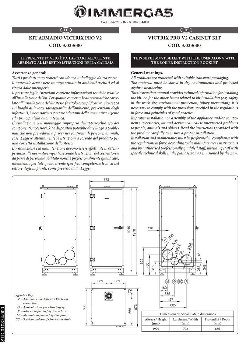
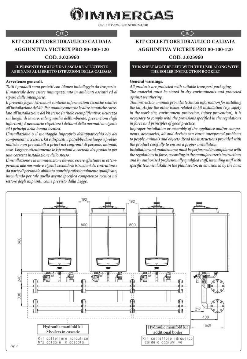
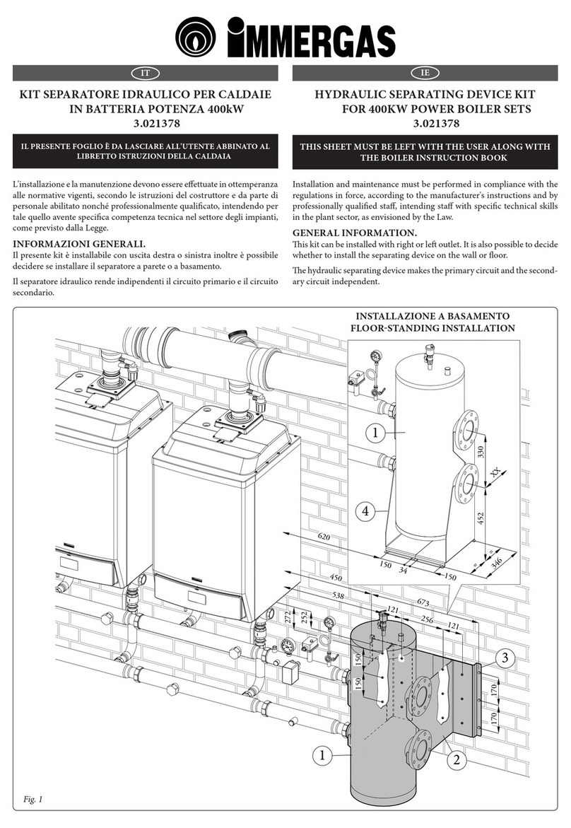
KIT COLLETTORE FUMI ø160 VICTRIX
SUPERIOR COD. 3.032852
IL PRESENTE FOGLIO È DA LASCIARE ALL'UTENTE
ABBINATO AL LIBRETTO ISTRUZIONI DELLA CALDAIA
FLUE MANIFOLD KIT VICTRIX SUPERIOR
Ø160 COD. 3.032852
THIS SHEET MUST BE LEFT WITH THE USER ALONG WITH
THE BOILER INSTRUCTION BOOKLET
AVVERTENZE GENERALI
Tutti i prodotti Immergas sono protetti con idoneo imballaggio da
trasporto.
Il materiale deve essere immagazzinato in ambienti asciutti ed al riparo
dalle intemperie.
Il presente foglio istruzioni contiene informazioni tecniche relative
all’installazione del kit Immergas. Per quanto concerne le altre tematiche
correlate all’installazione del kit stesso (a titolo esemplicativo: sicurez-
za sui luoghi di lavoro, salvaguardia dell’ambiente, prevenzioni degli
infortuni), è necessario rispettare i dettami della normativa vigente ed
i principi della buona tecnica.
L’installazione o il montaggio improprio dell’apparecchio e/o dei com-
ponenti, accessori, kit e dispositivi Immergas potrebbe dare luogo a
problematiche non prevedibili a priori nei confronti di persone, animali,
cose. Leggere attentamente le istruzioni a corredo del prodotto per una
corretta installazione dello stesso.
L'installazione e la manutenzione devono essere eettuate in ottem-
peranza alle normative vigenti, secondo le istruzioni del costruttore e
da parte di personale abilitato nonché professionalmente qualicato,
intendendo per tale quello avente specica competenza tecnica nel settore
degli impianti, come previsto dalla Legge.
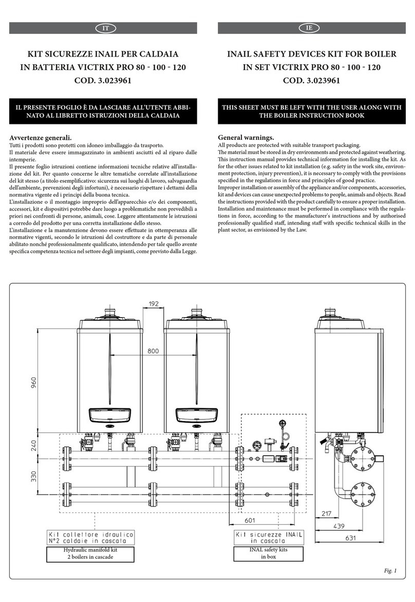
Scarico dei fumi
Nel caso di installazioni in cascata (batteria) composta da un massimo
di 2 derivazioni è possibile collettorizzare ad un unico condotto di
scarico fumi, che conuisca in canna fumaria.
La Immergas fornisce separatamente alle caldaie un sistema di scarico
fumi appropriato ed originale Ø 160 (Fig. 4).
Per il corretto montaggio del kit occorre tuttavia tenere in conside-
razione le seguenti indicazioni:
- i generatori devono essere disposti sulla stessa linea orizzontale;
- il collettore di scarico deve avere un'inclinazione minima di 3°;
- lo scarico dell'acqua di condensa prodotta dagli apparecchi deve
essere fatto conuire in una rete fognaria;
N.B.: vericare ed eventualmente regolare la portata termica di ogni
singolo apparecchio (vedi parag. regolazioni potenza termica del
libretto istruzioni della caldaia).
GENERAL WARNINGS
All Immergas products are protected with suitable transport packaging.
e material must be stored in a dry place protected from the weather.
is instruction manual provides technical information for installing
the Immergas kit. As for the other issues related to kit installation (e.g.
safety in the workplace, environmental protection, accident prevention),
it is necessary to comply with the provisions specied in the regulations
in force and with the principles of good practice.
Improper installation or assembly of the Immergas appliance and/or
components, accessories, kits and devices can cause unexpected problems
for people, animals and objects. Read the instructions provided with the
product carefully to ensure proper installation.
Installation and maintenance must be performed in compliance with the
regulations in force, according to the manufacturer's instructions and by
professionally qualied sta, meaning sta with specic technical skills
in the plant sector, as envisioned by the law.
Fume exhaust
In case of installation of in cascade (bank) boilers made up of ma-
ximum 2 joints, fumes can be collected into a single exhaust duct
joining with a ue.
Immergas separately supplies an appropriate and original, Ø 160
fume exhaust system (Fig. 4).
For correct assembly of the kit, the following indications must be
taken into consideration:
- the generators must be arranged on the same horizontal line;
- the exhaust manifold must have a min. slope of 3°;
- the drain for condensate produced by the appliances must be run
into a drainage system;
N.B.: check, and if necessary adjust the heat input of each applian-
ce (see boiler instructions handbook, thermal power adjustment
paragraph).
1
2
4
3
6
5
7
8
2
1
1
23
2
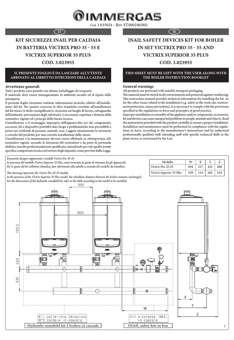
Composizione kit:
Rif. Qtà Descrizione
1 2 Distanziale 80 valvola fumi
2 2 Valvola di non ritorno sui fumi
3 1 Connessione DN 80 L=80
4 1 Connessione DN 80 L=122
5 1 Collettore DN 160 L=275
6 1 Collettore DN 160 L=870
7 1 Collettore DN 160 L=236
8 1 Sifone scarico condensa
Kit composition:
Ref. Qty Description
1 2 Spacer ø80 ue valve
2 2 Non-return valve on ue
3 1 Connection DN 80 L=80
4 1 Connection DN 80 L=122
5 1 Manifold DN 160 L=275
6 1 Manifold DN 160 L=870
7 1 Manifold DN 160 L=236
8 1 Condensate drain siphon
800 308 135
311
369,5
3°
D. 160
90
34
22
567
8
4
3
INSTALLAZIONE (FIG. 1)
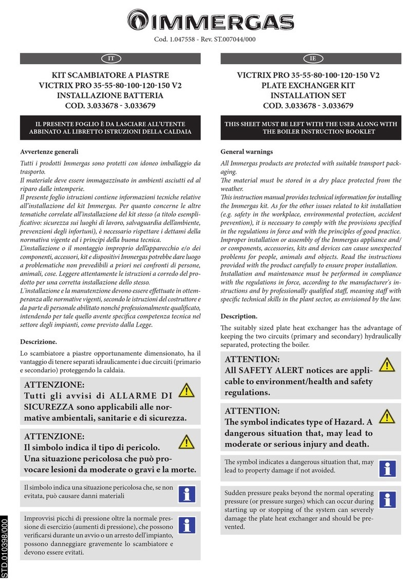
Innestare i distanziali 80 (1) all'interno delle ange di ogni singola
caldaia. Installare le valvole di non ritorno sui fumi (2) sulle ange
di ogni singola caldaia sino a portarle a battuta sui distanziali (1)
precedentemente montati. Riempire il sifone di ogni singola valvola
di non ritorno sui fumi con acqua, come indicato in g. 3. Innestare
le connessioni (3 e 4) sulle relative valvole di non ritorno sui fumi
(2). Innestare il collettore (6) al collettore (5) portandolo in battuta.
Posizionare il gruppo appena creato, collettori (5) e (6) sulle rispettive
connessioni ed avvitare le ghiere sui relativi accoppiameti. Innestare
il collettore (7) al collettore (6) portandolo in battuta. Innestare ed
avvitare il sifone scarico condensa (8) al collettore (7).
N.B.: per garantire la corretta inclinazione del collettore di scarico ed
il corretto interasse di collegamento tra le caldaie, durante l’installa-
zione del kit può essere necessario tagliare a misura rispettivamente
le connessioni (3 e 4) e/o i collettori (6 e 7).
N.B.: una volta terminato l’assemblaggio, occorre portarsi sul cru-
scotto di caldaia ed impostare “SI” nel menù fumisteria alla voce
“Abilita valvola klapet” (in caso di alimentazione con gas Propano
è necessario selezionare anche il tipo di gas “LG”). Successivamente
procedere con una Taratura veloce (un’eventuale analisi di combu-
stione con valori di CO2 inattesi potrebbe essere dovuta a condizioni
esterne indotte dal collegamento alla canna fumaria collettiva).
Per maggiori dettagli vedere il libretto di caldaia.
Scarico condensa. Per lo scarico dell’acqua di condensazione pro-
dotta dall’apparecchio, occorre collegarsi alla rete fognaria mediante
tubi idonei a resistere alle condense acide utilizzando il sifone (8,
Fig. 1). Il collegamento con la rete fognaria deve essere eettuato in
modo tale da evitare il congelamento del liquido in esso contenuto.
Prima della messa in funzione dell’apparecchio accertarsi che la
condensa possa essere evacuata in modo corretto. Occorre inoltre
attenersi alla normativa vigente (UNI 11528) ed alle disposizioni
nazionali e locali vigenti per lo scarico di acque reue.
INSTALLATION (FIG. 1)
Engage the Ø80 (1) spacers inside the anges of every individual
boiler. Install the one-way valves on the ue (2) on the anges of
every boiler until they to the end stop on the spacers (1) mounted
previously. Fill the siphon of every non-return valve on the ue
with water, as shown in g.3. Engage the connections (3 and 4) on
the relative one-way valves on the ue (2). Engage manifold (6) to
manifold (5) to the end stop. Place the created unit, collectors (5)
and (6) on the respective connections and screw the ring nuts on
the relative couplings. Engage manifold (7) to manifold (6) to the
end stop. Engage and screw the condensate drain siphon (8) to the
manifold (7).
NOTE: to guarantee the correct inclination of the exhaust manifold
and the correct connection centre distance between the boilers, du-
ring the installation of the kit it may be necessary to cut connections
(3 and 4) and/or manifolds (6 and 7) respectively.
NOTE: after completing the assembly, move to the boiler control
panel and set “YES” in the ue menu under item “Enable klapet val-
ve” (in case of Propane gas, the “LG” type gas must also be selected).
en proceed with a quick Calibration (any combustion analysis
with unexpected CO2 values could be due to external conditions
induced by the connection to the collective ue).
For further details, refer to the boiler manual.
Condensate drain. To drain the condensate produced by the ap-
pliance, it is necessary to connect to the drainage system by means
of acid condensate resistant pipes using the siphon (8, Fig. 1). e
connection with the drainage system must be set up so as to prevent
the liquid in it from freezing. Before appliance start-up, ensure that
the condensate can be correctly removed. Also, comply with stan-
dards in force with national and local regulations on discharging
waste waters.
IT IE
10
8
7
9
1
2
6
5
4
Scarico dei fumi
Nel caso di installazioni in cascata (batteria) composta da un massimo
di 3 derivazioni è possibile collettorizzare ad un unico condotto di
scarico fumi, che conuisca in canna fumaria.
La Immergas fornisce separatamente alle caldaie un sistema di scarico
fumi appropriato ed originale Ø 160 (Fig. 6).
Per il corretto montaggio del kit occorre tuttavia tenere in conside-
razione le seguenti indicazioni:
- i generatori devono essere disposti sulla stessa linea orizzontale;
- il collettore di scarico deve avere un'inclinazione minima di 3°;
- lo scarico dell'acqua di condensa prodotta dagli apparecchi deve
essere fatto conuire in una rete fognaria;
N.B.: vericare ed eventualmente regolare la portata termica di ogni
singolo apparecchio (vedi parag. regolazioni potenza termica del
libretto istruzioni della caldaia).
Fume exhaust
In case of installation of in cascade (bank) boilers made up of ma-
ximum 3 joints, fumes can be collected into a single exhaust duct
joining with a ue.
Immergas separately supplies an appropriate and original, Ø 160
fume exhaust system (Fig. 6).
For correct assembly of the kit, the following indications must be
taken into consideration:
- the generators must be arranged on the same horizontal line;
- the exhaust manifold must have a min. slope of 3°;
- the drain for condensate produced by the appliances must be run
into a drainage system;
N.B.: check, and if necessary adjust the heat input of each applian-
ce (see boiler instructions handbook, thermal power adjustment
paragraph).
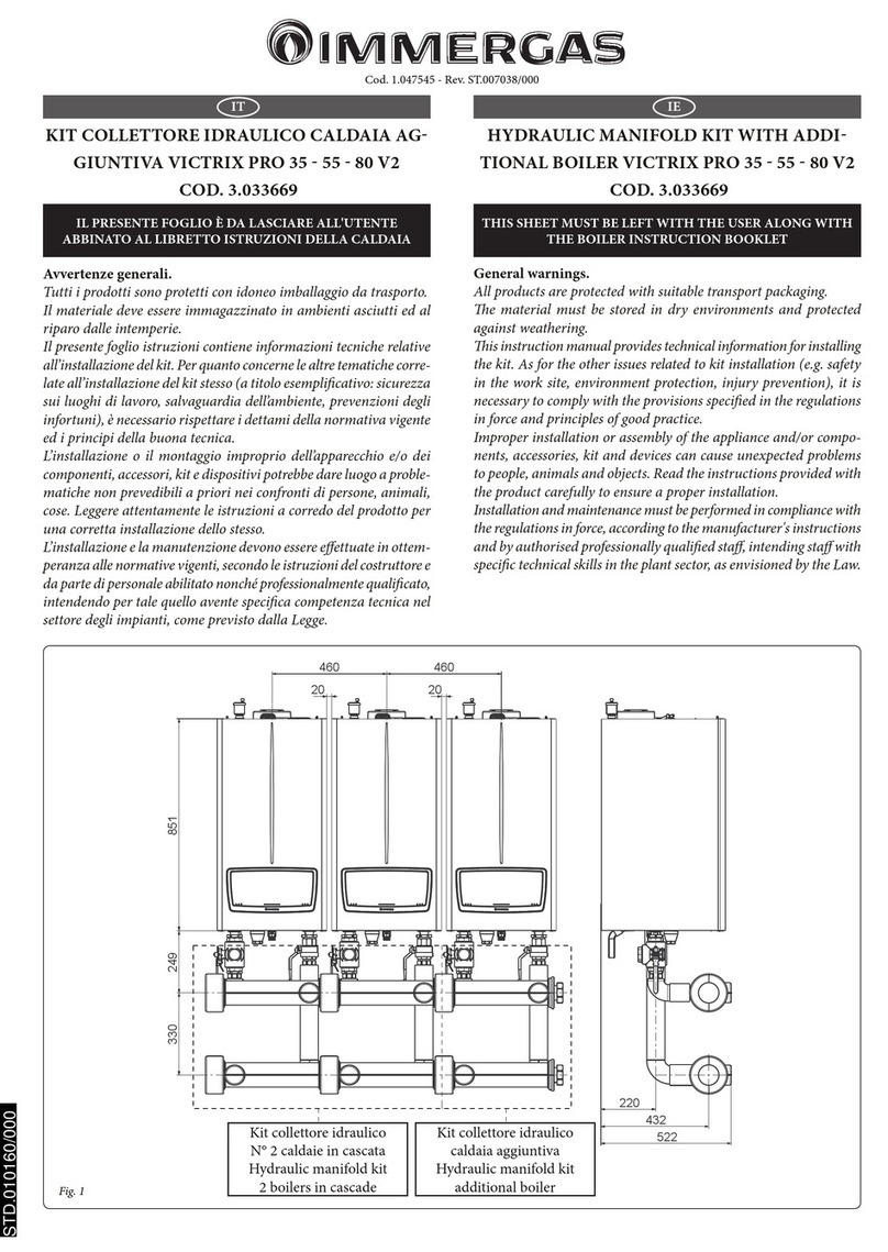
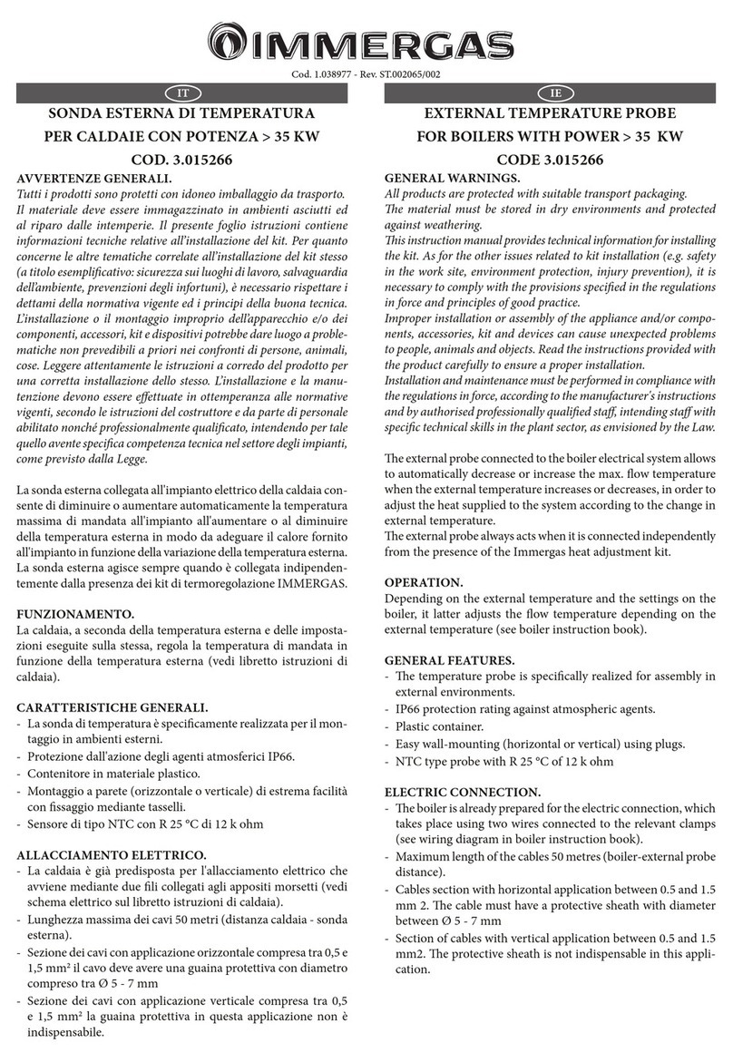
KIT COLLETTORE FUMI PER
AMPLIAMENTO ø160 VICTRIX SUPERIOR
COD. 3.032853
FLUE MANIFOLD KIT FOR EXTENSION Ø160
VICTRIX SUPERIOR COD. 3.032853
Composizione kit
Rif. Qtà Descrizione
1 1 Distanziale 80 valvola fumi
2 1 Valvola di non ritorno sui fumi
9 1 Connessione DN 80 L=248
10 1 Collettore DN 160 L 870
Kit composition
Ref. Qty Description
1 1 Spacer ø80 ue valve
2 1 Non-return valve on ue
9 1 Connection DN 80 L=248
10 1 Manifold DN 160 L 870
800 800 308 135
311
411
3°
D. 160
90
222
34
5610 7
8
9
6
5
INSTALLAZIONE (FIG. 1)
Innestare il distanziale 80 (1) all'interno della angia di caldaia.
Installare la valvola di non ritorno sui fumi (2) sulla angia di caldaia
sino a portarle a battuta sul distanziale (1) precedentemente montato.
Riempire il sifone della valvola di non ritorno sui fumi con acqua,
come indicato in g. 3. Innestare la connessione (9) sulla valvola
di non ritorno sui fumi (2). Innestare il collettore (10) al collettore
(6) portandolo in battuta. Posizionare il collettore (10) sulla con-
nessione (9) e stringere avvitando la ghiera. Innestare il collettore
(7) al collettore (10) portandolo in battuta. Innestare ed avvitare il
sifone scarico condensa (8) al collettore (7)
N.B.: per garantire la corretta inclinazione del collettore di scarico ed
il corretto interasse di collegamento tra le caldaie, durante l’installa-
zione del kit può essere necessario tagliare a misura rispettivamente
la connessione (9) e/o il collettore (10).
N.B.: una volta terminato l’assemblaggio, occorre portarsi sul cru-
scotto di caldaia ed impostare “SI” nel menù fumisteria alla voce
“Abilita valvola klapet” (in caso di alimentazione con gas Propano
è necessario selezionare anche il tipo di gas “LG”). Successivamente
procedere con una Taratura veloce (un’eventuale analisi di combu-
stione con valori di CO2 inattesi potrebbe essere dovuta a condizioni
esterne indotte dal collegamento alla canna fumaria collettiva).
Per maggiori dettagli vedere il libretto di caldaia.
Scarico condensa. Per lo scarico dell’acqua di condensazione pro-
dotta dall’apparecchio, occorre collegarsi alla rete fognaria mediante
tubi idonei a resistere alle condense acide utilizzando il sifone (8,
Fig. 5). Il collegamento con la rete fognaria deve essere eettuato in
modo tale da evitare il congelamento del liquido in esso contenuto.
Prima della messa in funzione dell’apparecchio accertarsi che la
condensa possa essere evacuata in modo corretto. Occorre inoltre
attenersi alla normativa vigente (UNI 11528) ed alle disposizioni
nazionali e locali vigenti per lo scarico di acque reue.
NSTALLATION (FIG. 1)
Engage the Ø80 spacer (1) in the boiler ange. Install the one-way
valve on the ue (2) on the boiler ange until they to the end stop
on the spacer (1) mounted previously. Fill the siphon of the non-
return valve on the ue with water, as shown in g.3. Engage the
connection (9) on the non-return valve on the ue (2). Engage
manifold (10) to manifold (6) to the end stop. Place the manifold
(10) on the connection (9) and tighten by screwing the ring nut.
Engage manifold (7) to manifold (10) to the end stop. Engage and
screw the condensate drain siphon (8) to the manifold (7)
NOTE: to guarantee the correct inclination of the exhaust manifold
and the correct connection centre distance between the boilers, du-
ring the installation of the kit it may be necessary to cut connections
(3 and 4) and/or manifolds (6 and 7) respectively.
NOTE: after completing the assembly, move to the boiler control
panel and set “YES” in the ue menu under item “Enable klapet val-
ve” (in case of Propane gas, the “LG” type gas must also be selected).
en proceed with a quick Calibration (any combustion analysis
with unexpected CO2 values could be due to external conditions
induced by the connection to the collective ue).
For further details, refer to the boiler manual.
Condensate drain. To drain the condensate produced by the ap-
pliance, it is necessary to connect to the drainage system by means
of acid condensate resistant pipes using the siphon (8, Fig. 5). e
connection with the drainage system must be set up so as to prevent
the liquid in it from freezing. Before appliance start-up, ensure that
the condensate can be correctly removed. Also, comply with stan-
dards in force with national and local regulations on discharging
waste waters.

Other Immergas Boiler Supplies manuals

Immergas VICTRIX SUPERIOR KIT User manual

Immergas

Immergas VICTRIX SUPERIOR KIT User manual

Immergas VICTRIX PRO 35 V2 Setup guide

Immergas

Immergas VICTRIX PRO 35 V2 Setup guide

Immergas 3.026302 User manual

Immergas

Immergas 3.026302 User manual

Immergas 3.015266 User manual

Immergas

Immergas 3.015266 User manual

Immergas Victrix Superior KW X User manual

Immergas

Immergas Victrix Superior KW X User manual

Immergas Victrix Pro 35-55 User manual

Immergas

Immergas Victrix Pro 35-55 User manual

Immergas 3.012944 User manual

Immergas

Immergas 3.012944 User manual

Immergas 3.023960 User manual

Immergas

Immergas 3.023960 User manual

Immergas INAIL VICTRIX PRO 80 User manual

Immergas

Immergas INAIL VICTRIX PRO 80 User manual

Immergas VICTRIX PRO 35 V2 SET User manual

Immergas

Immergas VICTRIX PRO 35 V2 SET User manual

Immergas 3.031186 Product manual

Immergas

Immergas 3.031186 Product manual

Immergas VICTRIX PRO V2 User manual

Immergas

Immergas VICTRIX PRO V2 User manual

Immergas 3.032264 Product manual

Immergas

Immergas 3.032264 Product manual

Immergas 3.020355 User manual

Immergas

Immergas 3.020355 User manual

Immergas 3.021378 User manual

Immergas

Immergas 3.021378 User manual

Immergas 3.018911 User manual

Immergas

Immergas 3.018911 User manual

Immergas 3.020934 User manual

Immergas

Immergas 3.020934 User manual

Immergas 3.031483 Product manual

Immergas

Immergas 3.031483 Product manual

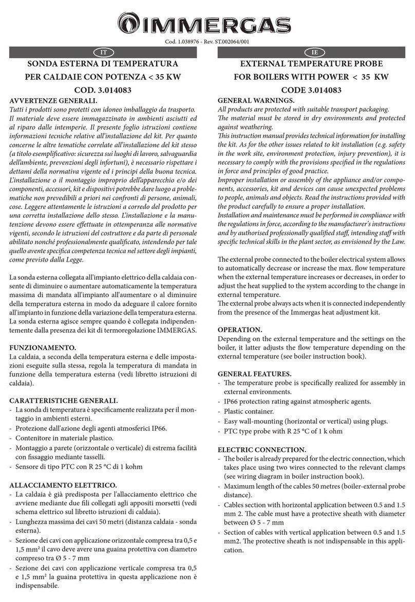
Immergas 3.014083 User manual

Immergas

Immergas 3.014083 User manual

Immergas VICTRIX PRO 35 V2 SET User manual

Immergas

Immergas VICTRIX PRO 35 V2 SET User manual

Immergas VICTRIX PRO 35 User manual

Immergas

Immergas VICTRIX PRO 35 User manual

Immergas Victrix TT Series Product manual

Immergas

Immergas Victrix TT Series Product manual

Immergas 3.030323 User manual

Immergas

Immergas 3.030323 User manual

Immergas 3.021377 User manual

Immergas

Immergas 3.021377 User manual

Popular Boiler Supplies manuals by other brands

ACV Prestige 85 Technical note

ACV

ACV Prestige 85 Technical note

oventrop Regumat RTA-130 Installation and operating instructions

oventrop

oventrop Regumat RTA-130 Installation and operating instructions

U.S. Boiler Company SteamMax STMX100 quick start guide

U.S. Boiler Company

U.S. Boiler Company SteamMax STMX100 quick start guide

Crown Boiler AM4 installation instructions

Crown Boiler

Crown Boiler AM4 installation instructions

oventrop Regumat S-130 Installation and operating instructions

oventrop

oventrop Regumat S-130 Installation and operating instructions

Hobart G1009 Installation, Use and Maintenance Instruction

Hobart

Hobart G1009 Installation, Use and Maintenance Instruction

Bosch 7738003218 installation instructions

Bosch

Bosch 7738003218 installation instructions

Centrometal Cm Pelet-set 90 Technical instructions

Centrometal

Centrometal Cm Pelet-set 90 Technical instructions

Honeywell AQ25A Series Technical reference booklet

Honeywell

Honeywell AQ25A Series Technical reference booklet

TriangleTube PSRKIT51 manual

TriangleTube

TriangleTube PSRKIT51 manual

QHT Direct Vent DVF-4 Rigid installation manual

QHT

QHT Direct Vent DVF-4 Rigid installation manual

manuals.online logo
manuals.online logoBrands
  • About & Mission
  • Contact us
  • Privacy Policy
  • Terms and Conditions

Copyright 2025 Manuals.Online. All Rights Reserved.