U.S. General Air Superiority 91831 User manual

®
©
3/8” IMPACT WRENCH
PIN CLUTCH COMPOSITE TYPE
Model 91831
ASSEMBLY AND OPERATING INSTRUCTIONS
3491 Mission Oaks Blvd., Camarillo, CA 93011
Visit ourWeb site at:http://www.harborfreight.com
TO PREVENT SERIOUS INJURY,
READ AND UNDERSTAND ALL WARNINGS
AND INSTRUCTIONS BEFORE USE.
Copyright 2004 by Harbor Freight Tools®. All rights reserved. No portion of this
manual or any artwork contained herein may be reproduced in any shape or form
without the express written consent of Harbor FreightTools.
For technical questions or replacement parts, please call 1-800-444-3353.

PRODUCT SPECIFICATIONS
SAVE THIS MANUAL
You will need this manual for the safety warnings and precautions, assembly, operating,
inspection, maintenance and cleaning procedures, parts list and assembly diagram.
Keep your invoice with this manual. Write the invoice number on the inside of the front
cover. Keep this manual and invoice in a safe and dry place for future reference.
GENERAL SAFETY RULES
WARNING!
READ AND UNDERSTAND ALL INSTRUCTIONS
Failure to follow all instructions listed in the following
pages may result in electric shock, fire, and/or serious injury.
SAVE THESE INSTRUCTIONS
SKU 91831 For technical questions please call 1-800-444-3353 PAGE 2
UNPACKING
When unpacking, check to make sure all the parts shown on the Parts List on page 8 are
included. If any parts are missing or broken, please call Harbor Freight Tools at the num-
ber shown on the cover of this manual as soon as possible.
Item Description
Drive Size 3/8” Square Drive
Free Speed 10,000 RPM
Maximum Torque 260 Ft./Lbs
Blows Per Minute 1,300
Maximum PSI 90 PSI
Cubic Feet Per Minute 4.0 CFM @ 90 PSI
Anvil Retainer Type Hog Ring
Air Inlet Size 1/4”-18 NPT
Inlet Screen 20-Mesh or Finer
Bolt Size Standard, 7/16”
Hose Size 3/8” I.D.
Regulator Settings Forward 1, Forward 2, Forward 3.
Reverse
Weight 2.7 Pounds

3. Keep bystanders, children, and visitors away while operating a pneumatic
tool. Distractions can cause you to lose control. Protect others in the work area
from debris such as chips and sparks. Provide barriers or shields as needed.
PERSONAL SAFETY
1. Stay alert. Watch what you are doing, and use common sense when oper-
ating a pneumatic tool. Do not use a pneumatic tool while tired or under
the influence of drugs, alcohol, or medication. A moment of inattention while
operating pneumatic tools may result in serious personal injury.
2. Dress properly. Do not wear loose clothing or jewelry. Contain long hair.
Keep your hair, clothing, and gloves away from moving parts. Loose
clothes, jewelry, or long hair can be caught in moving parts.
3. Avoid accidental starting. Be sure theTrigger (43) is off before connect-
ing to the air supply. Carrying pneumatic tools with your finger on the Trigger,
or connecting pneumatic tools to the air supply with the Throttle Lever on,
invitesaccidents.
4. Remove adjusting keys or wrenches before turning on the tool. A wrench
or a key that is left attached to a rotating part of the tool may result in personal
injury.
5. Do not overreach. Keep proper footing and balance at all times. Proper
footing and balance enables better control of the tool in unexpected situations.
6. Use safety equipment. Always wear ANSI approved safety glasses under-
neath a full face shield, and hearing protection.
TOOL USE AND CARE
1. Use clamps or other practical ways to secure and support the workpiece to
a stable platform. Holding the work by hand is unstable and may lead to loss of
control. Only work on a workpiece that is properly secured.
2. Do not operate pneumatic tools in explosive atmospheres, such as in the
presence of flammable liquids, gases, or dust. Pneumatic tools create sparks
which may ignite flammables.
1. Keep your work area clean and well lit. Cluttered benches and dark areas
invite accidents.
WORK AREA
SKU 91831 For technical questions please call 1-800-444-3353 PAGE 3

2. Do not force the tool. Use the correct tool for your application. The correct
tool will do the job better and safer at the rate for which it is designed.
3. Do not use the power tool if theTrigger does not turn it on or off. Any tool
that cannot be controlled with the Throttle Lever is dangerous and must be re-
placed.
4. Disconnect the air hose from the tool before making any adjustments,
changing accessories, or storing the tool. Such preventive safety measures
reduce the risk of starting the tool accidentally.
5. Store idle tools out of reach of children and other untrained persons. Tools
are dangerous in the hands of untrained users.
6. Maintain tools with care. Do not use a damaged tool. Tag damaged tools “Do
not use” until repaired.
7. Check for misalignment or binding of moving parts, breakage of parts,
damaged air hose (not included), and any other condition that may affect the
tool’s operation. If damaged, have the tool serviced before using. Many
accidents are caused by poorly maintained tools.
8. Use only accessories that are recommended by the manufacturer for your
model. Accessories that may be suitable for one tool may become hazardous
when used on another tool.
SERVICE
1. Tool service must be performed only by qualified repair personnel. Service
or maintenance performed by unqualified personnel could result in a risk of injury.
2. When servicing a tool, use only identical replacement parts. Follow
instructions in the
“Inspection, Maintenance, And Cleaning”
section of this
manual. Use of unauthorized parts or failure to follow maintenance instructions
may create a risk of injury.
SKU 91831 For technical questions please call 1-800-444-3353 PAGE 4
SPECIFIC SAFETY RULES
1. Maintain labels and nameplates on the Impact Wrench. These carry impor-
tant information. If unreadable or missing, contact Harbor Freight Tools for a
replacement.
2. To avoid accidental injury, always wear ANSI approved safety glasses, a
full face shield, and hearing protection when operating the Impact Wrench.

SKU 91831 For technical questions please call 1-800-444-3353 PAGE 5
3. Use clean, dry, regulated, compressed air at 90 PSI. Do not exceed the
recommended 90 PSI. Never use oxygen, carbon dioxide, combustible gases, or
any other bottled gas as a power source for this tool.
4. When connecting to the air supply: Prior to each use, if an automatic oiler is
not
used, add two drops of air tool oil (not included) into the Air Inlet (47) fitting of
the Impact Wrench.
5. Always disconnect the Impact Wrench from its compressed air supply
source, and squeeze theTrigger (43) to release all compressed air in the
tool after use and before performing any maintenance or services.
6. Industrial applications must follow OSHA requirements.
7. WARNING! The warnings, precautions, and instructions discussed in this
manual cannot cover all possible conditions and situations that may occur. The
operator must understand that common sense and caution are factors which
cannot be built into this product, but must be supplied by the operator.
ASSEMBLY AND OPERATING INSTRUCTIONS
NOTE: For additional references to the parts listed in the following pages, refer to the
Assembly Diagram on page 9.
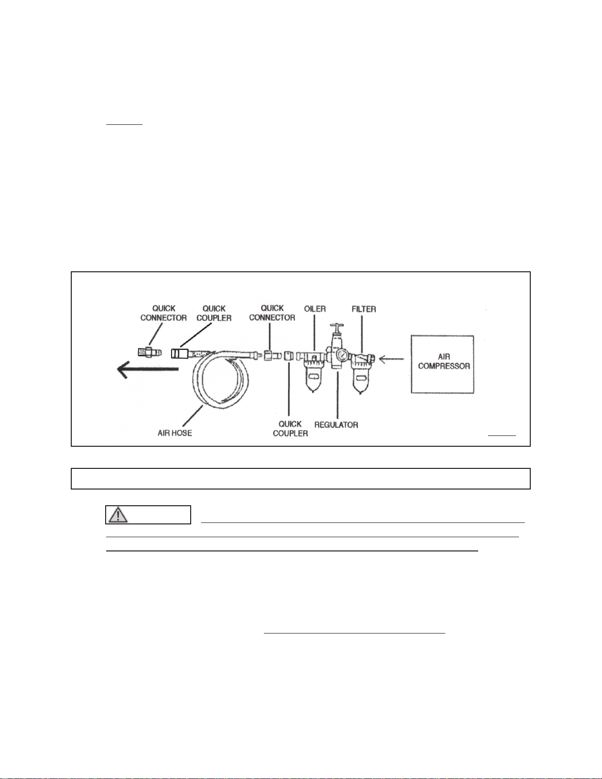
To Attach A Quick Connector:
1. WARNING! Prior to performing any assembly and/or adjustment
procedures, make sure the air supply hose (not included) is disconnected
from the Impact Wrench.
2. Prior to use, the Impact Wrench requires the attachment of a
Quick Connector
(not included) into its Air Inlet (47). To do so, wrap approximately 3” of pipe
thread sealer tape (not included) around the male threads of a Quick Connector.
Then, firmly tighten the Quick Connector into the Air Inlet.
(See Figure A, next page.)
To Operate The Impact Wrench:
1. WARNING! always wear ANSI approved safety glasses, a full face
shield, and hearing protection when operating the Impact Wrench.

SKU 91831 For technical questions please call 1-800-444-3353 PAGE 6
2. Select the 3/8” square drive Impact socket (not included) you wish to use, and
insert the socket firmly onto the 3/8”Anvil (11) of the ImpactWrench.
(See Figure A.)
3. Turn the Forward/Reverse Valve (30) to the desired direction in which the tool will
rotate. There is only
one
speed for the Reverse (counterclockwise) direction,
and there are
three
speeds for the Forward (clockwise) direction:
“F1” = Slow Speed / “F2” = Medium Speed / “F3” = High Speed.
(See Figure A.)
FIGURE A
4. Connect the air supply hose to the Quick Connector on the Impact Wrench. Turn
on the air compressor, and set its regulator to the recommended 90 PSI for the
Impact Wrench. (See Figure B, next page.)
5. In order to keep the air supply hose out of the way, hang it over your shoulder.
6. IMPORTANT! Grip the Impact Wrench firmly with both hands.
7. Insert the attached 3/8” square drive socket onto the bolt or nut you wish to
screw/unscrew, and with both hands firmly gripping the Impact Wrench apply
forward pressure to keep the socket from slipping off the bolt or nut.
F 3
REAR VIEW
REVERSE F 1 F 2
QUICKCONNECTOR
(NOTINCLUDED)
3/8” ANVIL
(11)
SIDE VIEW
TRIGGER
(43)
AIR INLET
(47)

SKU 91831 For technical questions please call 1-800-444-3353 PAGE 7
10. When finished, release pressure on theTrigger (43) to turn off the Impact
Wrench.Turn off the air compressor. Squeeze the Trigger of the Impact Wrench
to release any remaining air pressure from the tool. Then, disconnect the Impact
Wrench from the air supply hose. (See Figure B.)
8. To start the Impact Wrench, squeeze the Trigger (43). To stop the Impact
Wrench, release pressure on the Trigger. (See Figure A.)
9. NOTE: Before starting a job, always perform a test operation to determine the
proper tightening time for the bolt or nut. If tightened for too long a period, the bolt
or nut
and
socket may be overstressed, stripped, or damaged. Do not depend on
the torque from the wrench for the final tightening. All bolts must have their tight-
ness verified by a torque wrench (not included).
FIGURE B
TO
IMPACT WRENCH
INSPECTION, MAINTENANCE, AND CLEANING
1. WARNING! Always make sure the Trigger (43) is in its “OFF” position,
and disconnect the Impact Wrench from its compressed air supply before
performing any inspection, adjustments, maintenance, or cleaning.
2. Before each use, inspect the general condition of the Impact Wrench. Check for
loose screws, misalignment or binding of moving parts, cracked or broken parts,
damaged air hose, and any other condition that may affect its safe operation. If
abnormal noise or vibration occurs, have the problem corrected by a qualified
technician before further use. Do not use damaged equipment.
3. Daily: With a clean cloth, remove all dirt, oil, and grease from the Impact
Wrench. If necessary, you may use a mild detergent. Do not use solvents, as
damage to the Impact Wrench may occur. Do not immerse the Impact Wrench in
any liquids.
RECOMMENDED COMPRESSED AIR SYSTEM

SKU 91831 For technical questions please call 1-800-444-3353 PAGE 8
PLEASE READ THE FOLLOWING CAREFULLY
THE MANUFACTURER AND/OR DISTRIBUTOR HAS PROVIDED THE PARTS LIST
AND ASSEMBLY DIAGRAM IN THIS MANUAL AS A REFERENCE TOOL ONLY.
NEITHERTHE MANUFACTURER OR DISTRIBUTOR MAKES ANY REPRESENTATION
OR WARRANTY OF ANY KIND TO THE BUYER THAT HE OR SHE IS QUALIFIED TO
MAKE ANY REPAIRS TO THE PRODUCT, OR THAT HE OR SHE IS QUALIFIED TO
REPLACE ANY PARTS OF THE PRODUCT. IN FACT, THE MANUFACTURER AND/
OR DISTRIBUTOR EXPRESSLY STATES THAT ALL REPAIRS AND PARTS
REPLACEMENTS SHOULD BE UNDERTAKEN BY CERTIFIED AND LICENSED
TECHNICIANS, AND NOT BY THE BUYER. THE BUYER ASSUMES ALL RISK AND
LIABILITY ARISING OUT OF HIS OR HER REPAIRSTOTHE ORIGINAL PRODUCT OR
REPLACEMENT PARTSTHERETO, OR ARISING OUT OF HIS OR HER INSTALLATION
OF REPLACEMENT PARTS THERETO.
PARTS LIST
NOTE: Some parts are listed and shown for illustration purposes only, and are not
available individually as replacement parts.
Part
#
Description Qt
y
. Part # Description Qt
y
.
1 Oil Seal 1 25 Valve Sleeve Gasket 1
2 Hammer Case 1 26 Valve Sleeve 1
3 Set Screw 1 27 Ball Bearing 1
4 Recoil Insert 4 28 O-Ring 1
5 Anvil Bushing 1 29 Spring Pin 1
6 Front Gasket 1 30 Forward/Reverse Valve 1
7 3/8” Anvil Collar 1 31 Spring 1
8 3/8” O-Ring 1 32 Rear Gasket 1
9 Steel Ball 21 33 Spacer 1
10 Washer 1 34 Air Channel Gasket 1
11 3/8” Anvil 1 35 Motor Housing 1
12 Spring 1 36 Screw 4
13 Hammer Pin 2 37 Spring Pin 1
14 Cam 1 38 Bushing 1
15 Cam Foundation 1 39 Valve Stem 1
16 Steel Ball 1 40 Spring 1
17 Hammer Cage 1 41 Exhaust Deflector 1
18 Ball Bearing 1 42 Spring Pin 1
19 Front End Plate 1 43 Trigger 1
20 Oil Seal 1 44 O-Ring 1
21 O-Ring 1 45 O-Ring 2
22 Rotor 1 46 Washer 1
23 Rotor Blade 6 47 Air Inlet 1
24 Cylinder 1 48 O-Ring 1

ASSEMBLY DIAGRAM
NOTE: Some parts are listed and shown for illustration purposes only, and are not
available individually as replacement parts.
SKU 91831 For technical questions please call 1-800-444-3353 PAGE 9
Table of contents
Other U.S. General Impact Driver manuals