System Requirements
• Linux, MacOSX, or Microsoft Windows 7/8/10
• Java Runtime Environment 1.6 (1.8 or newer recommended)
• Web Browser: Google Chrome (Other browsers may have
limited functionality.)
• UniFi Controller software v4.7 or higher (available at:
www.ubnt.com/download/unifi)
Network Topology Requirements
• A DHCP-enabled network (for the AP to obtain an IP address
as well as for the wireless clients after deployment)
• A UniFi Cloud Key or management station running the UniFi
Controller v4.7 (or newer) software, located either on-site
and connected to the same Layer-2 network, or off-site in
the cloud or a NOC
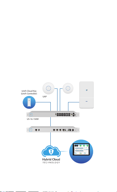
US-16-150W
USG-PRO-4
(DHCP Server)
Internet
UAP-AC-PRO UAP-AC-LR
LAN
WAN
UniFi Cloud Key
(UniFi Controller)
UAP-AC Outdoor
Remote Access to
UniFi Controller
DOWNLOADTHROUGHPUT&LATENCY DEVICESON2.4GHZCHANNEL
DEVICESON5GHZCHANNEL
UPLOADTHROUGHPUT&LATENCY
LATENCY THROUGHPUT
SPEEDTEST
msec Mbps
7 0.94 1
2.33
25 22
597
0.9 116
200+0700+0
0.01 413
2290.2
2118
547
ACTIVEDEVICE
WAN
Inacve 0
Pending
0
Inacve 0
Pending
0
7
ACTIVEDEVICES
Inacve 0
Pending
0
118
ACTIVEDEVICES
LAN WLAN
DEEPPACKETINSPECTIONCLIENTSDEVICES
250
200
150
100
50
0
10
8
6
4
2
0
24HRS 12HRS NOW
Avg/MaxThroughput Latency
Latency[msec]
Throughput[Mbps]
100
80
60
40
20
0
10
8
6
4
2
0
24HRS 12HRS NOW
Latency[msec]
Throughput[Mbps]
NetworkProtocols
StreamingMedia
Web/Web2.0
FileTransfer
SocialNetwork
Other
Motorola
Lenovo
SamsungE
Dell
Acer
Other
WLAN
LAN
WAN
118
7
1
582GB
23.3GB
22.7GB
8.47GB
3.6GB
5.46GB
258
241
220
213
130
110
126
DEVICES
645GB
TRAFFIC
1172
CLIENTS
1 2 3 4 5 6 7 8 9 10 11
36 40 44 48 52 56 60 64
100 104 108 112 116 120 124 128
132 136 140 144 149 153 157 161 165
CURRENTSITE
Default
USERNAME
admin
Sample Network Diagram
All UniFi devices support off-site management controllers. For
setup details, see the User Guide on the website:
www.ubnt.com/download/unifi