Ude MX-100B User manual

MATRIX
(8 inputs / 8 outputs)
SORTIE TEL.
R.C. OUT
OFF ON
ATTENUATION
ON
ON
ENTREE
INPUT
PRIORITE
PRIORITY
ENTREE
INPUT
SORTIE
OUTPUT
FUNCTION
FONCTION
PRIORITE
PRIORITY
ENTREE
INPUT
SORTIE
OUTPUT
FUNCTION
FONCTION
PRIORITE
PRIORITY
ENTREE
INPUT
SORTIE
OUTPUT
FUNCTION
FONCTION
PRIORITE
PRIORITY
ENTREE
INPUT
SORTIE
OUTPUT
FUNCTION
FONCTION
PRIORITE
PRIORITY
ENTREE
INPUT
SORTIE
OUTPUT
FUNCTION
FONCTION
PRIORITE
PRIORITY
ENTREE
INPUT
SORTIE
OUTPUT
FUNCTION
FONCTION
PRIORITE
PRIORITY
ENTREE
INPUT
SORTIE
OUTPUT
FUNCTION
FONCTION
PRIORITE
PRIORITY
ENTREE
INPUT
SORTIE
OUTPUT
FUNCTION
FONCTION
23456781
OFF
F
DEGRADE
PRIORITE
PRIORITY
MX-100B
191
610.246A
rev.0
EQUIPOS Y SISTEMAS MEGAFONÍA / INTERCOM PUBLIC ADDRESS SYSTEMS
Tel.: +34 934 772 854 / +34 609 914 787

5
3
3
5
10
10
5
5
6
6
7
7
7
8
9
9
11
15
11
12
12
12
13
13
15
16
18
16
16
17
19
19
19
19
1. DESCRIPTION
2. OPERATION -USE
3. PROGRAMMING
4. CONFIGURATIONS
5. MX-100B (8 x 8) TECHNICAL CHARACTERISTICS
1.1. 8 x 8 MATRIX
1.2. 16 x 16 MATRIX
2.1. INPUTS
2.1.1. musical inputs
2.1.2. paging microphone inputs and messages player (with telecommand)
2.1.3. paging microphone MX-101 input
2.2. OUTPUTS
2.3. PRIORITIES
2.3.1. Default configuration of the 8 x 8 Matrix
2.3.2. Default configuration of the 16 x 16 Matrix
2.4. ATTENUATION (NIGHT-DAY)
2.5. BY-PASS MODE (OPERATION)
2.6. LOGICAL OUTPUTS
2.7. DEFAULT CONTACT
3.1. PROGRAMMING FROM THE FRONT PANEL OF THE MX-100B MATRIX
3.1.1. Choice of the input to configure - Menu F1
3.1.2. Configuration of a musical input - Menu F2
3.1.3. Configuration of an input with telecommand (PZ-39, GD-26) - Menu F3
3.1.4. Choice of the output (to set the priority of the input in the output) - Menu F4
3.1.5. Configuration of the priority of an input in an output - Menu F5
3.2. PROGRAMMING FROM THE MX-101 DIGITAL PAGING MICROPHONE
3.3. PROGRAMMING THROUGH THE SOFTWARE SF-101
4.1. CONFIGURATION OF THE MX-100B MATRIX
4.2. CONFIGURATION OF THE INTERFACE RS232C / RS485
4.3. CONFIGURATION OF THE TIMING (PROGRAMMING KEYS)
4.4. INPUT / OUTPUT BOARD (CONFIGURATION)
5.1. 8 x 8 MATRIX
5.2. 16 x 16 MATRIX
5.3. GENERAL CHARACTERISTICS
2
MX-100B

F
23456781
11
12
9
4
31
2 6 7
58
13
14
15
10
MX-100B MATRIX FRONT PANEL (8 inputs / 8 outputs)
1. DESCRIPTION
1.1. 8 x 8 Matrix
Remark:
Particularities of the input:
The MX-100B Matrix (19 inches, 3U, battery-sector) permits to commute 8 inputs towards 8 outputs*, all this
according with nowadays requirements of the public-address systems.
*: the interconnection of two MX-100B Matrices makes possible to obtain a 16x16 Matrix.
This product is made up in a standard way by 8 modulus of inputs-outputs, each one of them composed by:
- One analogical input over a DIN plug-in (with telecommand) and over a socket RJ45 (for the MX-101 digital
paging microphone) with a sensitivity ruling on the front panel.
It is only possible to connect one input on each card of input-output (over the Din plug-in or over the
RJ45 plug-in), but never both at the same time.
- symmetric.
- micro level or line (selection through the corresponding button).
- limitator.
- One 0 dB symmetric analogical output over DIN plug-in with telecommand. Attenuation: 0 dB, -3 dB o -6 dB.
- RS422 communication port on an RJ45 socket (communication with the MX-101 digital paging microphone.
9
5
7
6
12 1311
14
15
8
4
2
The front panel is composed by:
- 1 tension presence led and an on-off interrupter .
- 1attenuation-warning led (day/night) .
- 1 by-pass mode warning led, : input n°1 in general call pushing
the button placed in the rear part of the product (the output telecommands are activated).
- 1 red button (F) which allows to go to the Configuration mode (with secure access) and to
choose the function to program.
4 red leds informing about the current programming:
- Choosing the input .
- Illuminated Output(s) to an input with telecommand (PZ-36, PZ-39, GD-26, …) .
- Illuminated Output(s) to an input without telecommand (musical source: CD, Tuner, …) .
- Configuration of the priority weight : 1 to 8 for an 8x8 Matrix (the weight 8 is the most important
priority).
- 1 sensitivity ruling per input .
- 1 function button for the programming by input/output .
- 3 green warning lights (input , output and priority ).
for the manual by-pass mode
1
3
3
MX-100B

17
16
27
25
24
31 23
22
20
26
2930
REAR PANEL OF THE MX-100B MATRIX
In addition to the battery-sector power supply , in the rear panel we find:
- 1 main communication port:
- RS422/RS485 over 4 points terminal block.
- RS232 over SubD9 female plug-in.
- 1 SubD37 plug-in and 1 SubD44 plug-in (interconnecting of two Matrices to obtain a 16x16
Matrix).
- 4 telecommands on terminal block, which permits for instance the starting up of the pre-
recorded messages of a digital lector (GD-26) (stopped: opened and started up: closed).
- 1 two-points plug-in for the "day/night" attenuation command. One jumper on each input-
output card which permits to choose the wanted attenuation for output when the command is
activated (contact closed):
- 0dB (there is no attenuation).
--3dB
--6dB
The input-output card is pre-configured on -6 dB.
- 1 button "DEGRADE 1 " (BY-PASS 1) to the manual by-pass mode (input 1 in general call). In
this by-pass mode, the Din plug-in " Input by-pass mode 2) " is not used.
- 1 Din plug-in " ENTREE DEGRADE 2 " (BY-PASS 2 INPUT) to plug in the (external) input that
will be automatically connected to the 8 outputs in case of power supply default. The telecommand
of this input allows in addition to commute this input in general call.
- 1 "PROG." Button for:
- When it is in use reinitialize the password which by default is "1234".
- When programming reinitialize the default Configuration (see chapter "Geographical
priority"). For security reasons, the access to this button in the rear panel is protected (it is necessary
to introduce a gadget in the hole to operate with this button).
- 1 two-points plug-in that indicates a power supply default (an opening between X and Y
indicates there is a default).
- 8 input-output blocks, each one composed by:
- 1 Din plug-in of input .
- 1 Din plug-in of output .
- 1 RJ45 plug-in (paging microphone MX-101 .
- 1 micro-line commuter .
By-pass mode (BpM): In the BpM the warning lights of the front panel are not managed (non
significant).
21
19
28
18
16
19
17
18
22
21
20 23 24
26
27
28
29
30
31
87654321
87654321
DIGITAL (16 x 16)
AUDIO
(16 x 16)
RS-232
25
4
MX-100B

1.2. 16 x 16 Matrix
(MX-100B Matrices off)
*: The cable CA-101 is composed by two SubD 44 points plugs-in. The plug-in marked as "MAITRE-
MASTER" identifies the master Matrix. The plug-in marked "ESCLAVE-SLAVE" identifies the slave Matrix.
master Matrix.
Remark 1:
Remark 2:
Remark 3:
Remark 4:
Remark 5:
See the previous chapter for the elements conforming an MX-100B Matrix.
The association of two MX-100B Matrices permits to obtain a 16x16 Matrix. To do this, it is necessary to
connect :
- The cable referred as CA-100 on the SubD 37- points plugs-in of each one of the Matrices.
- The cable referred as CA-101 * on the SubD 44-points plugs-in of each one of the Matrices.
When the master and slave Matrices are switched on, the synchronization phase between the two Matrices is
visualized by the red leds of the These Matrices illuminate in a successive way clockwise.
Is strictly necessary to switch off the two Matrices before doing the interconnection.
Detecting an operation on 8x8 or 16x16 is automatic. No Configuration is needed.
The master Matrix is determined by the connection of the cable containing the two SubD44 (one
plug-in is marked as Master and the other as Slave).
The inputs and outputs from 1 to 8 are over the master Matrix. The inputs and outputs from 9 to 16
are in the slave Matrix.
For the BY-PASS 1 mode (manual mode), it is necessary to configure:
- On the master Matrix: S1=ON y S2=OFF
- On the slave Matrix: S1= OFF y S2= ON
2. OPERATION USE
2.1. Inputs
It is possible to connect on each input of the MX-100B Matrix one of the following inputs:
- One musical input (CD player, tuner …).
- Or one input "with telecommand" (paging microphone PZ-36, paging microphone PZ-39, GD-26 …).
- Or a digital paging microphone MX-101.
Each input can have a different priority on each output (except the musical inputs where the priority level is 0).
Normally, the level selector must be in the position "LINE" for a musical input.
2.1.1. Musical inputs
If one or several inputs have been configured as an input without telecommand (musical input), then during the
switching on, the MX-100B Matrix commutes automatically the musical input on the configured outputs.
The musical inputs do not have any priority. If one prior input (PZ-39, GD-26, MX-101, …) activates, then the
zone(s) of the musical input are disconnected and then reconnected when the prior input becomes again
inactive.
Synchronization phase
between the two matrices
F
INPUT
PRIORITY
OFF ON
F
INPUT
PRIORITY
OFF ON
F
INPUT
PRIORITY
OFF ON
5
MX-100B

Example 1:
Example 2:
Input 1 "Paging microphone PZ39 input" (programming: E1 S1).
Input 8 "Musical input" (programming: E8 S1, S2).
In the Example N°1, the musical input connected on the outputs 1 and 2 is in pause.
- output 1 is disconnected from the musical input (E8)
- output 1 is connected on the paging microphone input (E1).
- output 1 is disconnected from the paging microphone input (E1)
- output 1 is reconnected on the musical input (E8).
Input 1 "Paging microphone input PZ39" (programming: E1 S1, S2, S3).
Input 8 "Musical input" (programming: E8 S1, S2).
In the Example N°2, the musical input connected on the outputs 1 and 2 is in pause.
- outputs 1 and 2 are disconnected from the musical input (E8)
- outputs 1,2 and 3 are connected on the paging microphone input (E1).
- outputs 1, 2 and 3 are disconnected from the paging microphone input (E1).
- outputs 1 and 2 are reconnected on the musical input (E8).
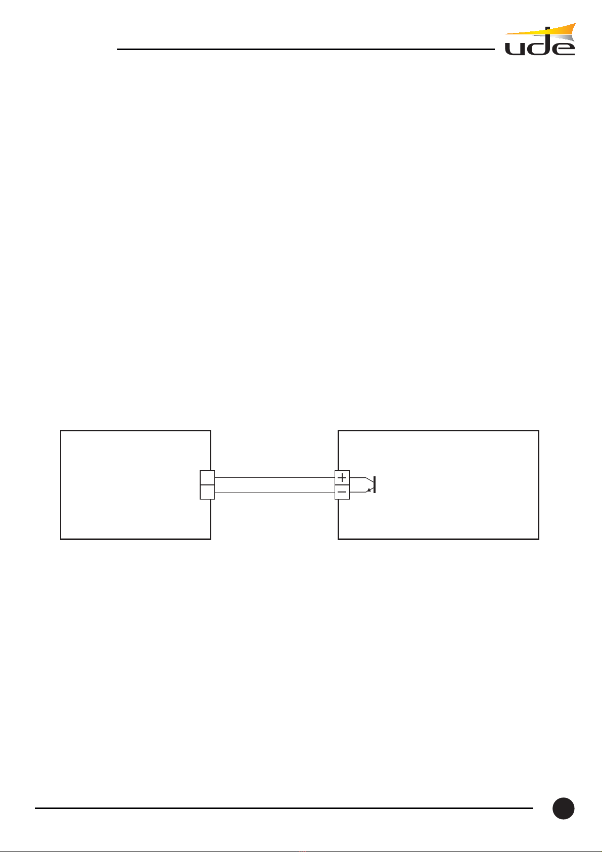
It is necessary to put the commuter of the musical input in the position line.
It is possible to program one or several outputs on a paging microphone input or for a messages player (with
telecommand):
- Paging microphone PZ-36.
- Paging microphone PZ-39.
- Messages player GD-26.
- ...
When the telecommand of the input in not active and if the input has a priority in one or several outputs then the
programmed output(s) are connected on the input.
When the telecommand of the input becomes again inactive, then the connected output(s) are disconnected
from the input.
The position of the level commuter depends on the connected input:
- Paging microphone PZ-39 level micro.
- Messages player GD-26 level line.
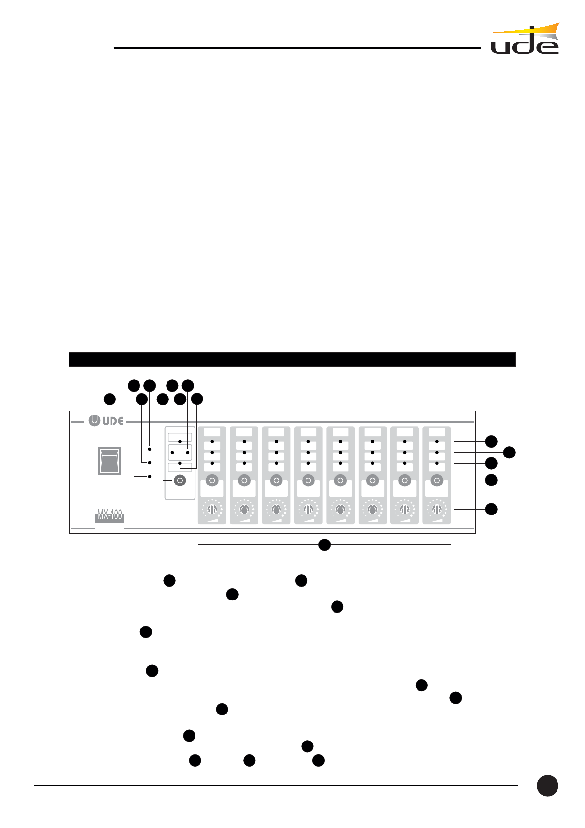
The microphone desk MX-101 makes possible to select one or several zones pressing the corresponding keys. In
this case, the MX-100B Matrix uses only the priority program. When the request is explicit enough, the Matrix
does not take into account the zones Configuration for an input connected to a microphone desk MX-101 (zones
configurations made on the Matrix).
When the output signal of the microphone desk MX-101 is 0dB it is necessary to put the commuter of the input
on the position "LINE".
When the paging microphone input (E1) is active (telecommand ON):
When the paging microphone input (E1) becomes again inactive (telecommand OFF):
When the paging microphone input (E1) is active (telecomman ON):
When the paging microphone input (E1) becomes again inactive (telecommand OFF):
2.1.2. Paging microphone inputs and messages player (with telecommand)
2.1.3. Paging Microphone MX-101 input
6
MX-100B

Input 1 "Message player GD-26", programming:
- E1 S1, S2, S3 y S4
- E1 priority 8 (S1), priority 8 (S2), priority 8 (S3) and priority 8 (S4)
Input 2 " paging microphone PZ-39 input", programming:
- E2 S1, S2 and S3
- E2 priority 1 (S1), priority 7 (S2), priority 1 (S3)
Input 3 "paging microphone PZ39 input", programming:
-E3 S2y S3
- E3 priority 1 (S2), priority 7 (S3)
- Input n°1 of the GD-26 has a priority over the other inputs in all zones.
- Input n°2 of the first paging microphone PZ39 has a priority over input n°3 in the zone n°2.
- Input n°3 of the second paging microphone PZ39 has a priority over the input n°2 in the zone n°3.
2.2. Outputs
2.3. Priorities
Remark:
Each one of the 8 outputs (or 16) of the MX-100B Matrix has a telecommand (pin 4) on the corresponding Din
plug-in.
The output level is symmetric.
The nominal level (output charged to 600 ) is between 0 dB and +12 dB (depending on the level of the
sensitivity ruling input).
A priority weight * can be programmed for each input (not musical). Each input can have a different priority on
each output.
*: 8x8 Matrix, weight 1 the weakest priority and weight 8 the strongest priority.
16x16 Matrix, weight 1 the weakest priority and weight 16 the strongest priority.
The Inputs configured as musical inputs have a level of priority 0. These do not activate the output's
telecommand.
Example:
2.3.1. Default configuration of the 8x8 Matrix
The MX-100B Matrix is configured in fabric with the inputs 1 to 7 as inputs with telecommand, with
geographical priority. Input n° 8 is configured as musical input connected to all outputs (see the table bellow).
O8
88888888
77777777
66666666
55555555
44444444
33333333
22222222
00000000X
X
X
X
X
X
X
X
XXXXXXX
O7O6O5O4O3O2O1O8O7O6O5O4
Outputs
INPUTS O3O2O1
I 1*
I 2*
I 3*
I 4*
I 5*
I 6*
I 7*
I 8
(musical)
Levels of Priority
7
MX-100B

*: Priority " weight" 1 the weakest priority.
Priority " weight " 8 the strongest priority
The button " PROG " placed in the rear panel makes possible to configure the MX-100B Matrix in the "by default"
mode. In order to do this, it is necessary to get into the programming mode.
2.3.2. Default configuration of the 16x16 Matrix
If two MX-100B Matrices are connected (16x16), the default configuration is the following (after pressing the
key " PROG " of the master matrix in the programming mode).
Procedure
- Press key F and enter password in order to get access to programming mode.
- Press push-button PROG on master matrix in order to program the default configuration.
XXXXXXX
X
X
X
X
X
X
X
X
X
X
XXXXXXXXX
X
X
X
X
X
Outputs
INPUTS O16O15O14O13O12O11O10O9O8O7O6O5O4O3O2O1
O16O15O14O13O12O11O10O9O8O7O6O5O4O3O2O1
I 1*
I 2*
I 3*
I 4*
I 5*
I 6*
I 7*
I 8*
I 9*
I 10*
I 11*
I 12*
I 13*
I 14*
I 15*
I 16
(musical)
I 1*
I 2*
I 3*
I 4*
I 5*
I 6*
I 7*
I 8*
I 9*
I 10*
I 11*
I 12*
I 13*
I 14*
I 15*
I 16
(musical)
0000000000000000
111111111111 11 11 11 11 11 11 11 11 11 11
10 10 10 10 10 10 10 10 10 10101010101010
99999999 99999999
8888888888888888
7777777777 777777
6666666666666666
555555555555 5555
4444444444444444
3333333333333333
2222222222
222222
12 12 12 12 12 12 12 12 12 12 12 1212121212
13131313 13 13 13 13 13 13 13 13 13 13 13 13
14 14 14 14 14 14 14 14 14 14 14 14 14 141414
1515 15 15 15 15 15 15 15 15 15 15 15 15 15 15
16 16 16 16 16 16 16 16 16 16 16 16 16 16 16 16
Levels of Priority
INPUTS
Default programming of the MX-100B Matrix (16x16).
- Priority " weight " 1 the weakest priority
- Priority " weight " 16 the strongest priority
8
MX-100B

F
23456781
F
23456781
Red Led:
ATTENUATION:
ON
Red Led
DEGRADE: ON
2.4.Attenuation (day-night)
One input (requested when closing) makes possible to attenuate the level of each output. The attenuation can be
done in one or several zones. In order to do this, it is necessary to configure each input-output card:
- S25 (1-2) 0 dB (there is no attenuation)
- S25 (2-3) -3 dB
- S25 (3-4) -6 dB
Attenuation Day/Night
The request may come for instance from a clock in order to make an attenuation by night in certain zones.
If for any reason (of technical type or not) it is necessary to go without the Matrix, is then possible to choose a
forced commutation of the signals. In this mode of operation all the outputs are connected to a predetermined
input. This mode is called BY-PASS mode.
The MX-100B Matrix has two functions to be used in by-pass mode.
This mode is reached in a manual way, pushing the button "BY-PASS 1" located in the rear panel of the product.
The red led "BY-PASS" illuminates over the front panel of the MX100B Matrix
(E1 in general call).
All the characteristics of the input n°1 (micro/line, phantom power supply, etc.) are kept as well as the ones of
the outputs (level, symmetry, etc.)
2.5. By-pass mode (DEGRADE) operation
By-pass mode 1:
and the input n°1 is connected to
all outputs
By-pass mode 1: input N°1 in general call
By-pass mode (BpM): In the BpM the warning lights of the Inputs and outputs of the front panel are not
managed (non significant).
Remark: In the case of a 16x16 Matrix it will be necessary to press the key "BY-PASS 1" of the master Matrix and
the slave Matrix. Both Matrices must have the following configuration:
- Master matrix: S1=ON and S2=OFF
- Slave Matrix: S1= OFF and S2= ON
Input 8 (musical)
current on
outputs 1, 2, 3 and 4
The music attenuates
9
MX-100B

C
2
GD-26 MX-100B
Telecommand
when closing
Logicial output of the
matrix commanded by
the paging microphone
By-pass mode 2 (DEGRADE 2):
Remark:
2.6. Logical outputs
In the case of the external input connected to the Din "BY-PASS 2 INPUT" it commutes on all the outputs
(external input in general call).
The red led "BY-PASS" on the front panel does not illuminate. This mode permits to go without the MX-100B
Matrix.
This mode can be activated in two ways:
1. Power supply default
In the casa of a power supply default, the Matrix goes automatically into this operation mode.
2. Telecommand
Activating the telecommand of the BY-PASS 2 input (point 4 of the DIN plug-in).
In the case of a 16x16 Matrix it is necessary to connect the external input to the Din "BY-PASS 2
INPUT" of the master Matrix and the slave Matrix.
The MX-100B Matrix has 4 telecommands (8 for the 16x16 Matrix) on the terminal block, making possible for
instance to play the pre-recorded messages of a digital player (GD-26).
Example telecommand of the message N°2 of the GD-26
2.7. Default contact
Remark:
The output is of type opened collector (pause: opened, operating: closed).
Attention the emitter is not referred and it is available on the terminal block. The telecommand may be activated
starting from:
- The F4 menu of a MX-101 microphone desk.
- The software SF-101.
One default contact (X-Y) is available on the rear panel of the MX-100B Matrix (contact opened in case of
default).
The contact X-Y points a default if the on-off interrupter is in the off position.
10
MX-100B

3. PROGRAMMING
3.1. Programming from the front panel of the MX-100B Matrix
Before using the Matrix, it is necessary to make the following configurations:
- Pre-attributions of outputs on one musical input (inactive telecommand), if the Matrix is connected to one or
several musical sources.
- Pre-attributions of outputs on one input with telecommand, if the Matrix is connected to one or several paging
microphones (PZ-39 …) or messages player (GD-26).
- Levels of priority of the inputs (with telecommand con and or MX-101 microphone desk). It is possible to
program a level of priority per input, different on each output.
The configuration of the MX-100B Matrix is made starting from:
- The front panel of the MX-100B Matrix * (with secure access).
- The MX-101 microphone desk (except the priorities programming).
- A PC with the software SF-101.
*: except for the 16x16 Matrix where the programming can only be made starting from the MX-101 microphone
desk or the software SF-101. The choice of a password gives only access to the default programming of the
16x16 Matrix.
To access to the programming mode push the red button F located in the front panel of the MX-100B Matrix.
The 4 red leds illuminate and the green leds form a cross informing that the access password is required to
continue. The password is " 1234",when the password is introduced one access to the programming mode.
Introduction of the password: one successive click of the leds indicates that the pressed key has been
successfully taken into account.
Programming mode
1.
2.
The return to the operation mode is automatic:
- On a 5 seconds delay before introducing the password (if no action has been detected by the Matrix).
- On a 30 seconds delay after introducing the password (if no action has been detected by the Matrix).
Once into the programming Mode, the key F permits to choose the following Menus:
F1. Choice of the input to configure
F2. Configuration of the output(s) to attribute to the input selected as a musical input (OUTPUT TEL . = OFF)
F3. Configuration of the output(s) to attribute to the input selected as an input with telecommand (OUTPUT TEL
. = ON)
F4. Choice of the output for programming a priority
F5. Configuration of the input's priority in this output
Each time the key F is pressed one access to the following programming function. Two cases may occur:
One musical input is programmed: in this case, each time F is pressed one access successively to
F1 F2 F1 F2 …
One input with telecommand is programmed: in this case, each time F is pressed one access successively to
F1 F2 F3 F4 F5 F1 F2 …
F
23456781
11
MX-100B

F
23456781
Menu F1:
Red Led
ON
Choice of the input
from 1 to 8.
Pushing the associated
function button
F
23456781Choice of the output
from 1 to 8 for adding
or removing.
Pushing the associated
function button
Menu F2:
Red Led
OUTPUT TEL.
OFF
Programming Menu F1: choice of the Input to program (E8 in the Example)
3.1.2. Configuration of a musical input - Menu F2
After choosing the input to configure, pressing the key F gives access to the Menu F2 (choice of the outputs
attributed to a musical input).
Programming Menu F2: Configuration of the outputs to attribute to a musical input (E8 in the Example)
3.1.3. Configuration of an input with telecommand (PZ-39, GD-26) - Menu F3
The previous configuration is shown. If the input is configured as a musical input, at least a green led (output)
illuminates. If the input is configured as an input with telecommand, the green leds of the outputs switch off.
In the Example above, Input N°8 is configured as a musical Input (outputs : 1,2,3,4,5,6,7 and 8).
For choosing or removing an output it is enough to push the associated function button.
It is necessary to access to the Menus F1 and F2 before accessing the Menu F3, (see the previous chapters).
To access the function F3 it is compulsory to unselect every output of the input on the Menu F2. This action
indicates to the Matrix that the Input is not a musical input.
After having unselected every output on the Menu F2, pressing the key F one access to the Menu F3 (choice of
the outputs attributed to one input having a telecommand).
3.1.1. Choice of the input to configure - Menu F1
Once being into the programming Mode, the red led "INPUT" illuminates. The 1rst time, the Matrix proposes the
input N°1 (INPUT 1 selected: green led illuminates).
If you wish to program input N°8 as a musical input, it is enough to push the FUNCTION N°8 button to choose
input N°8.
12
MX-100B

F
23456781Choice of the output
from 1 to 8 for adding
or removing.
Pushing the associated
function button
Menu F3:
Red Led
OUTPUT TEL
ON
F
23456781Choice of the output from
1 to 8 to program the priority
of the input (in this output).
Pushing the associated
function button
Menu F4:
Red Led
PRIORITY:
ON
Programming Menu F3: Configuration of the outputs to endorse to one input with telecommand (Input N°1
in the Example)
3.1.4. Choice of the output (to program the priority of the input in the output) - Menu F4
In the previous Example, input N°1 is configured as an input with telecommand on the outputs from 1 to 4.
For choosing or removing an output it is enough to push the associated function button.
It is necessary to access to the Menus F1, F2 and F3 before accessing the Menu F4, (see the previous chapters).
One click with the F key gives access to the Menu F4.
One output is proposed, if this is not convenient another one is chosen pushing the associated function button.
Programming Menu F4: choice of the output (output N°4 in the Example)
3.1.5. Configuration of the priority of an input in an output - Menu F5
F
For choosing an output it is enough to push the associated function button.
It is necessary to access to the Menus F1, F2, F3 and F4 before accessing the Menu F5, (see the previous
chapters). One click with the key gives access to the Menu F5.
The current priority is shown, if this is not convenient, another one may be chosen pushing the associated
function button.
F
23456781
Choice of the priority
from 1 to 8 of the input
in the output.
Pushing the associated
function button
Menu F5:
Red Led
PRIORITY:
ON
Programming Menu F5: Configuration of the priority of one input in an output (in the Example, the input N°1
to a priority of " weight " 8 in the output N°4)
13
MX-100B

O8O7O6O5O4O3O2O1O8O7O6O5O4
Outputs
INPUTS
Levels of Priority
O3O2O1
I 1
I 2
I 3
I 4
I 5
I 6
I 7
I 8
Programming of the MX-100B Matrix (8x8)
For choosing a priority it is enough to push the associated function button. Pressing the key gives
access to the Menu F1.
If the configured priorities are not known, it is recommended to program the default
configuration (see chapter 2.3.1). Once the programming of the Matrix is made, it is recommended
to note the Configuration in the following table.
F
Remark:
O16O15O14O13O12O11O10O9O8O7O6O5O4
Outputs
INPUTS O3O2O1
I 1
I 2
I 3
I 4
I 5
I 6
I 7
I 8
I 9
I 10
I 11
I 12
I 13
I 14
I 15
I 16
(musical)
14
MX-100B

O16O15O14O13O12O11O10O9O8O7O6O5OS4
Levels of Priority
INPUTS O3O2O1
I 1
I 2
I 3
I 4
I 5
I 6
I 7
I 8
I 9
I10
I11
I 12
I 13
I 14
I 15
I 16
(musical)
Programming of the MX-100B Matrix (16x16).
3.2. Programming from the paging microphone MX-101
3.3. Programming from the software SF-101
S27 on
the position 1-2.
S27 on the position 2-3
Consult the technical manual of the microphone desk MX-101.
The MX-100B Matrix is configured in "FABRIC" for operating in RS232. The length of the communication cable
that connects the PC to the MX-100B Matrix will determine the type of communication to use:
- Plug-in SubD9 Port series RS232 (maximal length 10 to 15 metres), Configuration "FABRICA"
- or RS422 on a terminal block (A,B,C,D), max length 1000 metres. This length will depend on the
environment, if this one is perturbed or much perturbed this length will be less than 1000 metres and possibly it
will be necessary to regenerate the signals with a repetidor. If this Mode of communication is used, then it will be
necessary to put the jumper (there only may be used one of the two ports of the MX-
100B Matrix).
The recommended cable is a cable:
- 2 pairs of 9/10th twisted (per pair).
- blinded per pair.
- with global screen.
The blinding of the pairs and the global screen will be connected to earth. In the case of a communication
RS422, the computer must have a series port of this type. On the contrary, it is necessary to enclose a modulus
of external conversion (interface RS232/RS422).
For the use of the software SF-101, see the instructions manual of the Configuration software of the MX-100B
Matrix.
15
MX-100B

87654321
87654321
ABC D
Txd+/Rxd+
Txd-/Rxd-
Rxd+
Rxd-
INTERFACE
RS232/RS422
MX-100B MATRIX
PC
RS232
SubD-9
SubD-25
RS422
T
2
T
1
R
3
R
4
Connection of the series port of the MX100B Matrix to a PC by the obliquity of an interface
RS232/RS422
4. CONFIGURATIONS
4.1. Configuration of the MX-100B Matrix
Remark:
The software SF-101, communicates with one and only one MX-100B Matrix connected on a series port. The
address of the Matrix must be configured to 0 and the Matrix must "charge the line": S20 = ON.
If one software application pilots several MX-100B Matrices on the same line RS485 then it is necessary:
- To configure a different address on each Matrix.
- Put S20 = ON over the Matrix at the end of the line.
- Put S20 = OFF over the Matrix or Matrices placed between the computer and the last Matrix.
the product N°1 = address 0 and the product N°16 = address 15
The address of the Matrix must be configured to 0 (Product N°1) with the software SF-101 (S14, S12, S10 and
S11 = ON).
S11
ONON
ON
OFF
ON
ON
ON
ON
OFF
OFF
OFF
OFF
OFF
OFF
OFF
OFF
8
9
10
11
12
13
14
15
OFF
ON
OFFOFF
ONON
ON OFF
ON
OFFOFFOFF
OFF
OFF
OFF
OFF
S10S12S14
9
10
11
12
13
14
15
16
Nº
MX-100B
Nº
Nº
MX-100B
1
0
2
3
4
5
6
7
Nº
2
1
3
4
5
6
7
8
S14
ON ON ON ON
ON ON
ON
ON
OFF
OFF
OFF
OFF OFF
OFF
ON
ON
OFF OFF
OFF
OFF
ON
ON
ON
OFF
OFF
ON
ON
ON
ON
ON
ON
ON
S12 S10 S11
ADDRESS RS485 ADDRESS RS485
16
MX-100B

(Cpu central card: 107.331A)
Configuration of the MX-100B Matrix
4.2. Configuration of the interface RS232C / RS485
4.3. Configuration of the temporization (programming keys)
If the computer does not have a series port RS422-RS485, then it will be necessary to enclose an external
modulus of conversion, between the series port RS232C of the PC and the MX-100B Matrix.
The following communication type must be chosen by the interface:
-TxON-RxON
- DCE
The keys located on the front panel of the Matrix permit to configure or test the MX-100B Matrix (8x8 only).
The jumper S16 makes possible to select two temporizations for avoiding the repetition of the key:
- S16 = OFF 350 ms
- S16 = ON 500 ms
J5
J3 J2 J1J4
DAY / NIGHT DEGRADE 1
PROG.
RS-422 / RS-485
J19
DIGITAL (16 x 16)
RS-232
S8
S11
S10
S12
S14
S17
S16
S15
S2 = OFF S1 = ON
S28 = ON
S9 = ON
S4 = ONS3 = ON
S23
S13 = ON(1-2)
S27 = ON(1-2)
13
22
31
Address RS485: S14, S12, S10, S11
For a communication with the program
SF-101, the direction must be programmed 0.
(See the configuration table above).
-
Tempo, between keys:
S16=OFF ®350 ms
S16=ON ®500 ms
S21=ON
S20=ON
S26=ON
S18
S21
S25
S20
S24
S26
S18=OFF
S25=OFF
S24=OFF S20 = ON :Only the Matrix which is at the end
of the line must charge the line
RS485 (S20=0N).
If the computer is connected only to one Matrix
then (S20=0N).
(Permits to insert the charge resistance at the
end of the line).
If the distance between PC computer and matrix is more than 15 meters, it is necessary to use serial port RS422
in order to secure the system.
To choose RS232 or RS422 serial port on the MX-100B matrix refer to chapter 3-3 (configuration thanks to
software SF-101)
17
MX-100B

JUMPER
JUMPERS FUNCTION
ON
ON
ON
ON
ON
ON
OFF
S19
S18
S20
S25
PZ-36 POWER SUPPLY
CM-101, PZ-39 POWER SUPPLY
FILTER ON SPEECH
FILTER ON MUSIC
-3 db OUTPUT ATTENUATION (WHEN THE “DAY / NIGHT INPUT” IS ACTIVATED
0 db
-6 db
STATUS FUNCTIONS
1-2
2-3
1-2
2-3
3-4
4.4. Input / Output board (107.330A) configuration.
SW1 Selector
BOARD
I-O E1 E2 E3 E4 E5 E6 E7 E8
1ON
ON
ON
ON
ON
ON
ON
ON
OFF
OFF
OFF
OFF
OFF
OFF
OFF
OFF
OFF
OFF
OFF
OFF
OFF
OFF
OFF
OFF
OFF
OFF
OFF
OFF
OFF
OFF
OFF
OFF
OFF
OFF
OFF
OFF
OFF
OFF
OFF
OFF
OFF
OFF
OFF
OFF
OFF
OFF
OFF
OFF
OFF
OFF
OFF
OFF
OFF
OFF
OFF
OFF
OFF
OFF
OFF
OFF
OFF
OFF
OFF
OFF
2
3
4
5
6
7
8
123
4
3
2
1
S18
S19 S20
S21 S22
ON
S14
E1
E2
E3
E4
E5
E6
E7
E8
SW1
DG1
J11
J10
J1
DG2
OUT
MIC-LINE
IN
DIGITAL
CONSOLE S12
S13
S11
S10
S9
S8
S7
S25
1
2
3
S3
S6 S1
S5
S2
S4
The selector allows the interconnection between the input signal and the internal audio bus. It is
imperative to set up the switchers according to here below installation
SW-1
18
MX-100B

5. MX-100B (8X8) TECHNICAL CHARACTERISTICS
5.1. 8x8 Matrix.
5.2. 16x16 Matrix
5.3. General characteristics
- Signal input :
- Line:
-Signal output:
- Answer in frequency:
- Particularities :
- Number of inputs : 8
- Number of outputs: 8
- Number of inputs : 16
- Number of outputs : 16
Symmetric
(level microphone or line selectable per commuter )
Microphone:
- Sensitivity : 1,5 mV
- Impedance : 600
- Phantom power supply: yes
- Talk/listen filter: yes
- Output for power supply PZ-36 yes
- Sensitivity : 250 mV
- Impedance : 22 K
Symmetric
- Level of output : 0 dBm (600 ) / +6 dBu
- Max level of output : +20 dBm
- Particularities (output) : Attenuation Day/Night: 0 dB / -3 dB / -6 dB.
(by external command see chapter Attenuation)
20 Hz a 20 kHz
- Possibility of mixing the Input signals
- Signal limitator
- Input sensitivity ruler
- Management of telecommands
- Attenuation Day/Night configurable
- Operation in by-pass Mode 1 and 2 (emergency situation)
- Power supply default indication
- Operation with up to 8 MX-101 digital paging microphones
- Programming:
- manual from the front panel (only for the 8x8 Matrix)
- with the MX-101 paging microphone
- with the software SF-101
- Power supply sector : 230 VAC (50/60 Hz) 0.3 A
- Battery power supply : +24 VDC 2 A
- Material: Metal.
- Color: Black.
- Weight: 12 Kg.
19
MX-100B
Table of contents
Other Ude Stereo System manuals