UE TX200H User manual

IMTX200H-03
www.ueonline.com
GENERAL
The TX200H is a registered HART 7 compliant device. It is a highly accurate,
rugged, SMART pressure transmitter that can communicate digitally and via
the 4-20 mA analog signal output. The TX200H utilizes the HART protocol
and an internal microcontroller to allow the end-user to easily configure and
calibrate the pressure transmitter as it provides process variable measure-
ment and device health data.
HART is an acronym for Highway Addressable Remote Transducer and it has
become the most widely adopted standard for industrial communication. The
Hart protocol is based on a standardized set of commands that is maintained
by the HART Communication Foundation (HCF) and allows any end-user to
easily integrate devices like the TX200H into their HART enabled system. The
TX200H, as a registered HART device has been designed to communicate
with other HART enabled devices such as a software package running on a
PC with HART interface or a field portable HART communicator.
BEFORE INSTALLING, CHECK THE SENSOR MODEL SELECTED FOR
COMPATIBILITY TO THE PROCESS MEDIA IN CONTACT WITH THE
SENSOR AND WETTED PARTS.
MISUSE OF THIS PRODUCT MAY CAUSE EXPLOSION AND PERSONAL
INJURY. THESE INSTRUCTIONS MUST BE THOROUGHLY READ AND
UNDERSTOOD BEFORE UNIT IS INSTALLED.
THIS EQUIPMENT IS SUITABLE FOR USE IN CLASS I, DIVISION
1, GROUPS A, B, C AND D; CLASS II, DIVISION 1, GROUPS E, F AND G;
CLASS III; OR NON-HAZARDOUS LOCATIONS ONLY. -40˚C (-40˚F) ≤
TAMB. ≤+85˚C (+185˚F), ENCLOSURE TYPE 4X.
THIS EQUIPMENT IS ATEX CERTIFIED FOR EQUIPMENT CATEGORY 2.
SUITABLE FOR APPROPRIATE USE IN GAS ZONE 1 AND DUST ZONE
21 APPLICATIONS.
EN 60079-0:2012, EN 60079-1:2007, EN 60079-31:2009
0539 DEMKO 08 ATEX 0810742X
II 2 G Ex d IIC T5 Gb
II 2 D Ex tb IIIC T90˚C Db
IP66
-40˚C ≤Tamb. ≤+80˚C
UE declarations and third-party issued Agency certifications are available for
download at www.ueonline.com/prod_approval.
PROOF PRESSURE* LIMITS STATED IN THE LITERATURE AND ON
THE TRANSMITTER HOUSING MUST NEVER BE EXCEEDED, EVEN
BY SURGES IN THE SYSTEM. OCCASIONAL OPERATION OF UNIT
TX200H™
HART®Pressure Transmitter
UP TO MAXIMUM PRESSURE IS ACCEPTABLE (E.G. START-UP, TESTING).
CONTINUOUS OPERATION SHOULD NOT EXCEED THE DESIGNATED OVER
RANGE PRESSURE**.
*Proof Pressure
The maximum pressure to which a pressure sensor may be occasionally sub-
jected, which causes no permanent damage (e.g., start-up, testing).
**Over Range Pressure
The pressure value to which a transmitter may be continuously subjected,
without causing a shift in calibration or damage to the sensor.
THESE PRODUCTS DO NOT HAVE ANY FIELD REPLACEABLE PARTS.
ANY SUBSTITUTION OF COMPONENTS MAY IMPAIR UNIT SAFETY AND
SUITABILITY FOR CLASS I, DIVISION 1.
THE EPOXY RESIN SHALL NOT BE SUBJECTED TO A TEMPERATURE
GREATER THAN 125˚C.
Please refer to product bulletin for product specifications. Product bulletin
may be found at www.ueonline.com
Date code format on nameplate is “YYWW” for year and week.
Part I - Installation
Tools Needed
Adjustable Wrench
MOUNTING
ALWAYS LOCATE UNITS WHERE SHOCK, VIBRATION AND AMBIENT
TEMPERATURE FLUCTUATIONS ARE MINIMAL. DO NOT MOUNT IN
AMBIENT TEMPERATURE AREAS EXCEEDING 185˚F / 85˚C (IF UL/
cUL APPROVAL IS APPLICABLE) OR 176˚F / 80˚C (IF ATEX APPROVAL IS
APPLICABLE).
IF SEVERE PRESSURE SURGES ARE EXPECTED, CONSIDER THE USE
OF A PRESSURE SNUBBER.
UNIT MAY BE MOUNTED IN ANY POSITION. ALWAYS HOLD A WRENCH
ON THE SENSOR FLATS (PRESSURE PORT) WHEN MOUNTING UNIT.
Panel Mounting via 1/2” NPTM or M20 Electrical Connection
When panel mounting, mount through 7/8” clearance hole in panel. Hold in
place with serrated 1/2” or M20 conduit nut. Always support the unit by hold-
ing a wrench on the hex fitting and not the housing body.
Installation and Maintenance
Instructions
Please read all instructional literature carefully and thoroughly before starting. Refer to the final page for the listing of Recommended
Practices, Liabilities and Warranties.
IMTX200H-03
HART® is a registered trademark of the
Hart Communication Foundation

IMTX200H-03
www.ueonline.com
WIRING
No special or separate wiring is required for digital communication with HART
devices since the HART FSK (Frequency Shift Keying) signal is superimposed
on top of the 4-20 mA output signal. Digital data is sent to and from the field
device via a HART master while real-time process information is available via
the 4-20 mA signal. It is recommended that a high quality twisted pair or
shielded wire cable be used where extended lengths are required or electrical
noise may be present.
NOTE: The TX200H is reverse bias protected so no damage will result in
the event of accidental reversal of power leads.
DISCONNECT ALL SUPPLY CIRCUITS BEFORE WIRING UNIT. ELECTRICAL
RATINGS STATED IN LITERATURE AND ON THE TRANSMITTER MUST
NOT BE EXCEEDED.
WIRE IN ACCORDANCE WITH LOCAL AND NATIONAL ELECTRICAL
CODES. THROUGH PROPER INSTALLATION, THE WIRES SHALL BE
PROTECTED AGAINST MECHANICAL DAMAGE, I.E. BY USE OF A
CONDUIT.
THE TX200H TRANSMITTER ACCEPTS A SUPPLY VOLTAGE OF 10-36
VDC AND SHALL NOT EXCEED 36 VDC. THE SUPPLY VOLTAGE MUST
BE ISOLATED FROM MAINS VOLTAGE BY DOUBLE/REINFORCED
INSULATION.
EARTH GROUND MUST ALWAYS BE CONNECTED TO THE GREEN WIRE
TO PROVIDE SHIELDING AND ELECTRICAL SAFETY.
THE TX200H WIRING MUST BE INSTALLED IN A GROUNDED METAL
CONDUIT OR WITH OTHER SUITABLE SHIELDING IN ORDER TO MEET
EUROPEAN EMC DIRECTIVE REQUIREMENTS.
ATEX REQUIREMENTS ONLY
THE WIRING TO THE PRESSURE SENSOR MUST ONLY BE CONNECTED
IN THE SAFE AREA OR BY AN APPROVED TERMINAL BOX CERTIFIED
TO EN 60079-0:2012, EN 60079-1:2007, EN 60079-31:2009 FOR
HAZARDOUS LOCATIONS.
EXTERNAL GROUNDING SCREW (OPTION M460) IS REQUIRED FOR
NON-METALLIC CONDUIT SYSTEMS (SEE FIGURE 1).
A 1/2” NPT (male) or M20 conduit connection is provided on the top of the
transmitter with 18 AWG, 72” length lead-wires. An external grounding screw
and clamp is provided when selecting option M460 (see figure 1). The lead-
wires are color coded as follows:
Red: +signal
Black: - signal
Green: Earth ground
Bench Operation:
To operate the TX200H on the bench, it must be connected to a power supply
and a load resistor (see Figure 2). The HART master (e.g., handheld com-
municator) may also be connected directly across the red and black wires at
the TX200H. A voltmeter across the 250 Ω resistor can be used to measure
the current in the loop ( Iloop = Vresistor / 250 ). At 4mA the voltmeter will
read 1 volt and at 20 mA the meter will read 5 volts.
Field Operation:
The TX200H can be connected to any HART compatible input card or module
or any standard 4-20mA input if the HART interface is not being used. In
most cases the power supply and the load resistor are built into the input
card or module (see Figure 3).
Power Supply/Load Limits:
For general operation of the TX200H while using HART the series loop resis-
tance should be between 230 to 600 ohms and the power supply voltage
should be 24V nominal.
The TX200H can be operated without the HART interface within the operating
limits of the power supply and loop resistance as shown in Figure 4.
Fault Currents:
Under normal operating conditions the analog output signal of the TX200H
will remain between 4-20mA. In the event that the pressure goes beyond
the operating range of the device or in a fault condition, the TX200H will indi-
cate the condition on the 4-20mA loop as follows:
Loop Current Description
3.7 mA Check Sum Error
3.9 mA Low Limit of Output Range
22.0 mA Upper Limit of Output Range
24 mA Fault Current
Figure 1
Figure 2
+
Power Supply
-
TX200H
HART Master or
Hand Held
Calibrator
Red
Black
250 Ω
Voltmeter
HART master/
handheld
communicator
Figure 3
Input Card/
Module TX200H
Red
Black
Green
Loop Resistance (max.)
Power Supply Voltage
Figure 4

IMTX200H-03
www.ueonline.com
Re-Ranging: Using the HART interface, the range of the TX200H can be
modified. This is useful in situations where the exact range transmitter is not
available. Re-Ranging is accomplished by changing the lower range value
and the upper range value to achieve the desired range. There are limita-
tions on the range adjustment. The lower/upper range limits must be within
the upper and lower sensor range (as marked on the transmitter body and
within the certificate of calibration) and the span must be greater that the
process variable (PV) minimum span programmed in the device. The PV min.
span is 10% of the range of the device for models with a pressure range of
≥ 100 psi and 20% of the range of the device for models with a pressure
range < 100 psi.
For example, a 1000 psi transmitter can be re-ranged to be a 100
psi transmitter.
Multi-Drop Mode: Using HART communication it is possible to connect
up to 15 field devices to a HART master over a single pair of wires. In this
topology (see Figure 5) the field device is placed in a fixed current mode and
all communication occurs over the HART interface. Each device is assigned a
unique poll address (1-15). This serves as a unique address so that the
master can access the field devices individually. NOTE: The TX200H ships
from UE with the poll address set to O. A poll address of 0 indicates the
device is not in multi-drop mode.
Zone Hazardous Locations Flameproof
Gap and Joint Details
Electrical conduit fitting threaded connection: M20 x 1.5, 7 threads minimum
engagement.
Part II - Set-Up
Tools Needed
HART Communicator or other Master
Using a HART handheld communicator, or other HART master,
you can access the many features of the TX200H.
Read Device Information: you can read information such as the model
number and revision, the device I.D. and the range of the sensor.
Device Setup: can be used to setup or commission a device prior to placing
it in service. These features allow the user to write things like a device tag
and a device description into the TX200H so that it can be uniquely identified
over the HART interface.
Basic/Detailed Setup Features Include:
1. Device Tag: The device tag identifies where the device will be
placed into service. A replacement device can be programmed to
have the same tag as the device it is replacing prior to installation.
2. Process Variable Units: Allows the user to select the units of mea-
sure (e.g., “wc, “Hg, psi, mbar, bar, kg/cm2, kPa, MPa).
3. Process Variable Limits: Allows the user to read the upper and
lower sensor limits and to read and adjust the upper and lower
range of the TX200H within the sensors limits and the allowable
turn-down range.
4. Device Description/Message: The user can program a text field that
reflects the function of the device.
5. Damping: The user can adjust the level of the damping applied to
the process variable. This feature is used to reduce the effect of
fluctuations in the readings. The value entered is the time constant
of the software filter, which adjusts the amount of damping.
Process Variables: can be read over the HART interface. Pressure is the
primary variable. Temperature is the secondary variable. NOTE: Reported
temperature is the ambient temperature at the back of the sensor and not
the process media temperature.
• Primary Variable: can be read in pressure units, percent of range or in mA.
• Secondary Variable: Available in °F
Diagnostic and Service: there are several TX200H diagnostic and service
features available over the HART interface.
1. Calibration: There are two ways to calibrate the TX200H.
a. If a calibrated pressure source is available, the user can apply a low
and high pressure and set the low and high range points.
b. If no pressure source is available, the user can manually enter values
for the upper range limit and the lower range limit.
2. D/A Trim: This feature allows the user to calibrate the D/A converter
that generates the 4-20mA signal. The output is first set to 4mA. The
user must measure and enter the loop current. The output is then set
to 20mA. The user again must measure and enter the loop current.
The output of the D/A is adjusted for offset and span.
3. Loop Test: The loop test feature forces the output current to a user
specified value. It can be set to 4mA, 20mA or to another value entered
by the user.
Figure 5
Red
Black
Red
Black
Red
Black
HART
Master
TX200H
#1
TX200H
#2
TX200H
#15
...

IMTX200H-03
www.ueonline.com
Pressure Connection Chart
Code Description Hex
“A”in
Length
“B”in [mm]
1 1/4” NPT (female) 15/16 0.54 [13.7]
2 1/2” NPT (female) 1-3/8 1.01 [25.7]
3 1/2” NPT (male) 15/16 1.26 [32.0]
4 HF4 Autoclave (female) 15/16 0.54 [13.7]
5 FH6 Autoclave (female) 1-3/8 0.90 [22.9]
6 LF4 Autoclave (female) 15/16 0.54 [13.7]
7 LF6 Autoclave (female) 15/16 0.65 [16.5]
8 1/4” NPT (male) 15/16 0.97 [24.6]
9 7/16-20 SAE (female) 15/16 0.54 [13.7]
A G-1/4 (female) 15/16 0.54 [13.7]
B G-1/2 (female) 1-3/8 1.01 [25.7]
C 7/16-20 SAE (male) 15/16 0.77 [19.6]
D HM4 Autoclave (male) 15/16 1.10 [27.9]
E HM6 Autoclave (male) 15/16 1.29 [32.8]
F LM4 Autoclave (male) 15/16 1.18 [30.0]
G LM6 Autoclave (male) 15/16 1.32 [33.5]
H G-1/4 (male) 15/16 1.03 [26.2]
J G-1/2 (male) 1-3/8 1.78 [45.2]
Code Range
03 = 0 to 15 psis
04 = 0 to 30 psis
05 = 0 to 50 psis
06 = 0 to 100 psis
07 = 0 to 250 psis
08 = 0 to 500 psis
09 = 0 to 1000 psis
17 = 0 to 1500 psis
18 = 0 to 2000 psis
10 = 0 to 2500 psis
19 = 0 to 3000 psis
11 = 0 to 5000 psis
20 = 0 to 6000 psis
12 = 0 to 7500 psis
13 = 0 to 10,000 psis
14 = 0 to 15,000 psis
15 = 0 to 20,000 psis
16 = 0 to 25,000 psis
Pressure Ranges
Option M423 & M513 Junction Boxes
M423
ATEX flameproof compliant junction box
(Not UL or cUL approved) M513
UL/CSA approved, explosion proof junction box
(Meets enclosure type 4 requirements only. Not ATEX compliant)
OR M20 (METRIC)
Wire Color Coding
Red + 4-20 mA
Black - 4-20 mA
Green Earth Ground
Part III - Dimensions
Dimensional drawings for all models may be found at www.ueonline.com

IMTX200H-03
www.ueonline.com
Part IV - TX200H HART COMMANDS
Command Number Universal Commands, Command Funcon
0Read Unique Idener Distributor, model, device id, tag, date, ID code, device type code (E18D) sw rev, device id,
1 Read Primary Variable
2Read Loop Current and Percentage of Range
3Read Current and up to Four Dynamic Variables
6Write Polling Address
7Read Loop Conguraon
8 Read Dynamic Variable Families
9Read up to Four Device Variables with Status
11 Read Unique Idener Associated with Tag
12 Read Message
13 Read Tag, Descriptor, Date
14 Read Primary Variable Transducer Informaon
15 Read Device Informaon
16 Read Final Assembly Number
17 Write Message
18 Write Tag, Descriptor, Date
19 Write Final Assembly Number
20 Read Long Tag
21 Read Unique Idener Associated with Long Tag
22 Write Long Tag
38 Reset Conguraon Changed Flag
48 Read Addional Device Status
Command Number Common-Pracce Commands, Command Funcon
33 Read Device Variables
34 Write Primary Variable Damping Value
35 Write Primary Variable Range Values
36 Set Primary Variable Upper Range Value
37 Set Primary Variable Lower Range Value
40 Enter/Exit Fixed Current Mode
42 Perform Master Reset
43 Set Primary Variable (Trim) Zero
44 Write Primary Variable Units
45 Trim Loop Current Zero
46 Trim Loop Current Gain
47 Write Primary Variable Transfer Funcon
54 Read Device Variable Informaon
59 Write Number of Responses Preambles
71 Lock Device (Allows a Master to temporarily or permanently lock the device)
76 Read lock status

IMTX200H-03
www.ueonline.com
CP04112000
UNITED ELECTRIC
CONTROLS
180 Dexter Avenue, P.O. Box 9143
Watertown, MA 02471-9143 USA
Telephone: 617 926-1000 Fax: 617 926-2568
http://www.ueonline.com
RECOMMENDED PRACTICES AND WARNINGS
United Electric Controls Company recommends careful consideration of the fol-
lowing factors when specifying and installing UE pressure and temperature units.
Before installing a unit, the Installation and Maintenance instructions provided
with unit must be read and understood.
• To avoid damaging unit, proof pressure and maximum temperature limits stated
in literature and on nameplates must never be exceeded, even by surges in the
system. Operation of the unit up to maximum pressure or temperature is accept-
able on a limited basis (e.g., start-up, testing) but continuous operation must be
restricted to the designated adjustable range. Excessive cycling at maximum
pressure or temperature limits could reduce sensor life.
• A back-up unit is necessary for applications where damage to a primary unit
could endanger life, limb or property. A high or low limit switch is necessary
for applications where a dangerous runaway condition could result.
• The adjustable range must be selected so that incorrect, inadvertent or mali-
cious setting at any range point cannot result in an unsafe system condition.
• Install unit where shock, vibration and ambient temperature fluctuations will
not damage unit or affect operation. When applicable, orient unit so that
moisture does not enter the enclosure via the electrical connection. When
appropriate, this entry point should be sealed to prevent moisture entry.
• Unit must not be altered or modified after shipment. Consult UE if modifica-
tion is necessary.
• Monitor operation to observe warning signs of possible damage to unit, such
as drift in set point or faulty display. Check unit immediately.
• Preventative maintenance and periodic testing is necessary for critical appli-
cations where damage could endanger property or personnel.
• Electrical ratings stated in literature and on nameplate must not be exceed-
ed. Overload on a switch can cause damage, even on the first cycle. Wire
unit according to local and national electrical codes, using wire size recom-
mended in installation sheet.
• Do not mount unit in ambient temp. exceeding published limits.
LIMITED WARRANTY
Seller warrants that the product hereby purchased is, upon delivery, free from
defects in material and workmanship and that any such product which is found to
be defective in such workmanship or material will be repaired or replaced by Seller
(Ex-works, Factory, Watertown, Massachusetts. INCOTERMS); provided, however,
that this warranty applies only to equipment found to be so defective within a
period of 36 months from the date of manufacture by the Seller. Seller shall not
be obligated under this warranty for alleged defects which examination discloses
are due to tampering, misuse, neglect, improper storage, and in any case where
products are disassembled by anyone other than authorized Seller’s representatives.
EXCEPT FOR THE LIMITED WARRANTY OF REPAIR AND REPLACEMENT STATED
ABOVE, SELLER DISCLAIMS ALL WARRANTIES WHATSOEVER WITH RESPECT TO
THE PRODUCT, INCLUDING ALL IMPLIED WARRANTIES OF MERCHANTABILITY
OR FITNESS FOR ANY PARTICULAR PURPOSE.
LIMITATION OF SELLER’S LIABILITY
SELLER’S LIABILITY TO BUYER FOR ANY LOSS OR CLAIM, INCLUDING LIABILITY
INCURRED IN CONNECTION WITH (I) BREACH OF ANY WARRANTY WHATSO-
EVER, EXPRESSED OR IMPLIED, (II) A BREACH OF CONTRACT, (III) A NEGLIGENT
ACT OR ACTS (OR NEGLIGENT FAILURE TO ACT) COMMITTED BY SELLER, OR (IV)
AN ACT FOR WHICH STRICT LIABILITY WILL BE INPUTTED TO SELLER, IS LIM-
ITED TO THE “LIMITED WARRANTY” OF REPAIR AND/OR REPLACEMENT AS SO
STATED IN OUR WARRANTY OF PRODUCT. IN NO EVENT SHALL THE SELLER BE
LIABLE FOR ANY SPECIAL, INDIRECT, CONSEQUENTIAL OR OTHER DAMAGES OF
A LIKE GENERAL NATURE, INCLUDING, WITHOUT LIMITATION, LOSS OF PROFITS
OR PRODUCTION, OR LOSS OR EXPENSES OF ANY NATURE INCURRED BY THE
BUYER OR ANY THIRD PARTY.
UE specifications subject to change without notice.
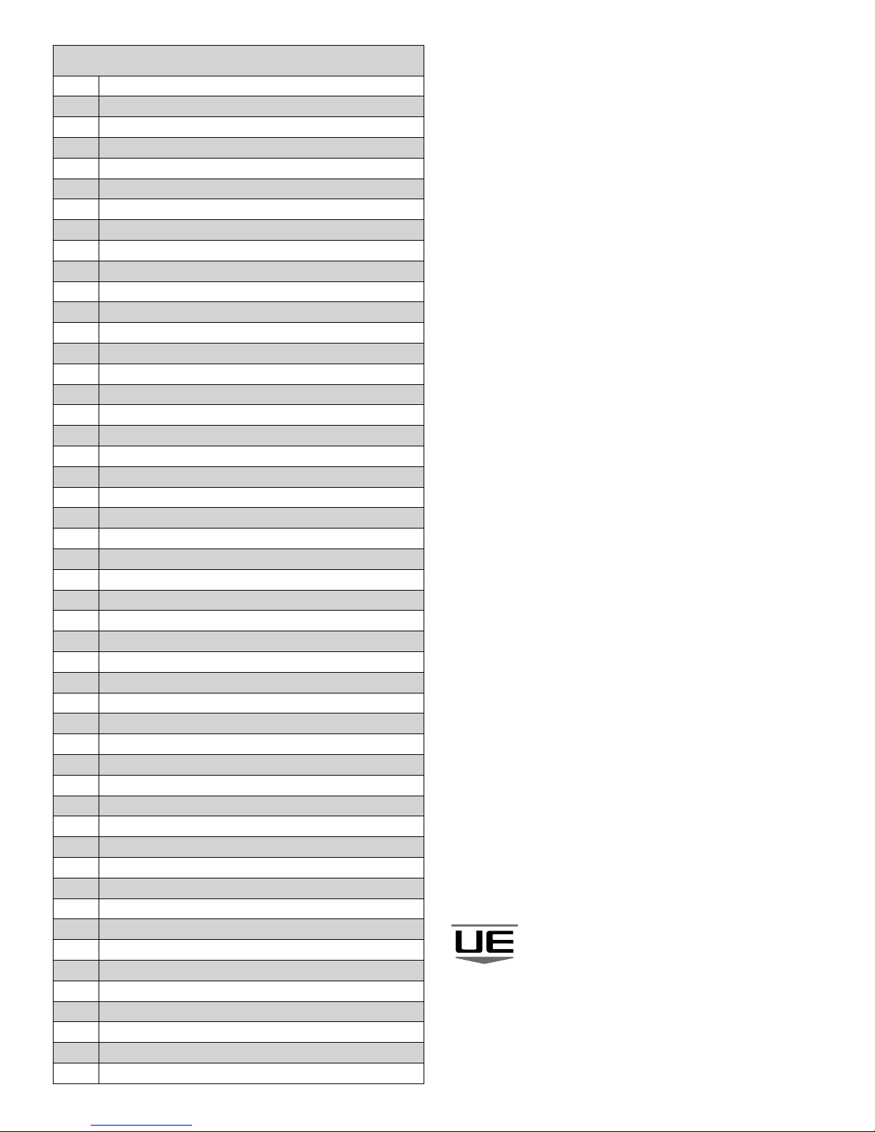
Response Codes
Code Descripon
0Success
2Invalid Selecon
3Passed Parameter Too Large
4 Passed Parameter Too Small
5 Too Few Data Bytes Received
6Error (Device Specic Command Error)
7In Write Protect Mode
8 Mul-Denion Warning
Update Failure
Set to Nearest Possible Value
All but running delayed responses ushed
9Mul-Denion Error
Lower Range Value too High
Applied Process too High
Not in Proper Current Mode
10 Mul-Denion Error
Lower Range Value too Low
Applied Process too Low
Invalid Local Panel Code
11 Mul-Denion Error
Upper Range Value too High
In Mul-Drop Mode
Invalid Device Variable Code
Trim Error Excess Correcon Aempted
Cannot Lock Panel
12 Mul-Denion Error
Upper Range Value too Low
Invalid Units Code
13 Mul-Denion Error
Both Upper and Lower Range Values Out of Limits
14 Mul-Denion Error
Span too Small
New Lower Range Value Pushed Upper Range Value Over Limit
16 Mul-Denion Error
Invalid Analog Channel Number
Access Restricted
17 Invalid Device Variable Index
18 Invalid Units Code
19 Device Variable Index Not Allowed
20 Invalid Extended Command Number
28 Invalid Range Units Code
30 Command Response Truncated
32 Busy
33 Delayed Response Iniated
34 Delayed Response Running
35 Delayed Response Dead
36 Delayed Response Conict
64 Command Not Implemented
Table of contents
Other UE Transmitter manuals