UIS WDI-220A User manual

Wireless Digital Input Transducer
Wireless Digital Input TransducerWireless Digital Input Transducer
Installation Guide
Features
Ability to send a signal wirelessly to the Gateway for monitoring a third party industrial detector status via DI/DO (dry contact)
digital signal.
Power Saving – one CR123A battery can be used for more than 1 year. It is also equipped with the low battery alert function.
Easy Setup – simply press the SET button on the device to join the system at the rst time.
Switch Link – when linked with other sensors, users can congure the device to be an automatic switch to control the home
automation devices (i.e. Power Switching).
Installation
I. Before Installation
1. Power on the Gateway.
2. Waiting for about 90 seconds until the Gateway led light become solid green instead of blinking.
Note: We suggest to use auto joining all device via APP at the rst time. Please refer to APP Quick Installation Guide.
II. Device Installation and Manual Joining
1. Install the batteries with the correct polarity (+/-) as shown inside the battery compartment.
Note: Do not use rechargeable battery.
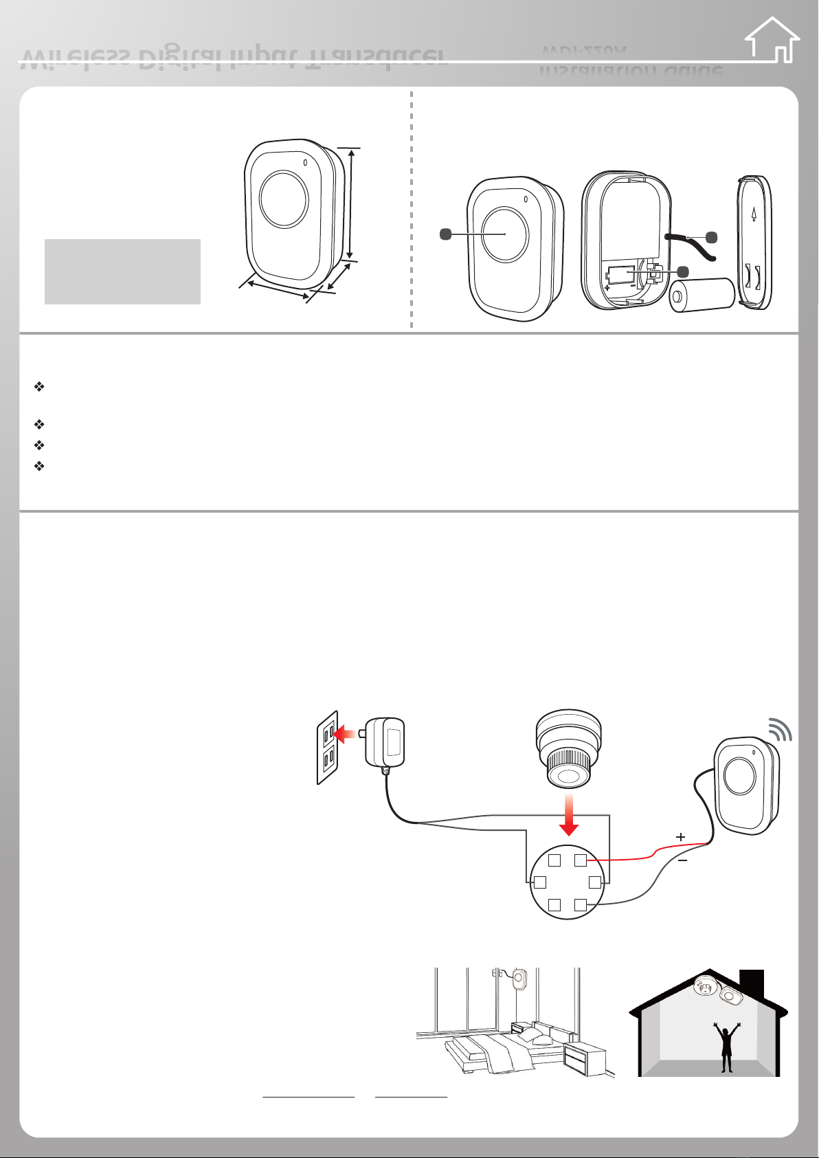
2. Connect the wiring pin of the third
party device via dry contact (DI/DO).
The illustration on the right shows the
description of integration and wiring
method:
Wire 1- (Red): Dry contact Input (Positive)
Wire 2- (White): Dry contact Input (Negative)
3. Press the SET button at the top of the Gateway or short press
the set button at the bottom of Router (Power Switching).
Then press the SET button of device.
4. The Gateway/Router and the Sensor are joining as both LED
indicators blink. The device blinks light red in 30 seconds.
LED indicators light red once and turned o, indicating
the device join process is successful.
Note: If the device join process is failed, both LED indicators on
those joined devices will light red and stop blinking after 30 sec.
5. Use the double-sided tap or athead screw to x bottom case.
WDI-220A
Overview
Name: Wireless Digital Input Transducer
Battery Type: CR123A x 1
Dimension: 71.9 x 48.8 x 21.5 mm
Accessories: Double-side Tape
Names of Parts
1. Status LED / SET Button
2. Outlet Wiring
3. Battery Slot
CAUTION
RISK OF EXPLOSION IF BATTERY IS
REPLACED BY AN INCORRECTTYPE.
DISPOSE OF USED BATTERIES
ACCORDINGTOTHE INSTRUCTIONS.
3
1
71.9mm
21.5mm
48.8mm
2
6 1
4 3
5 2CX-96R
Red
White
DC+
DC12v
Adapter
DC
-
CO sensor
CX-96RCODetectorWiring Diagram
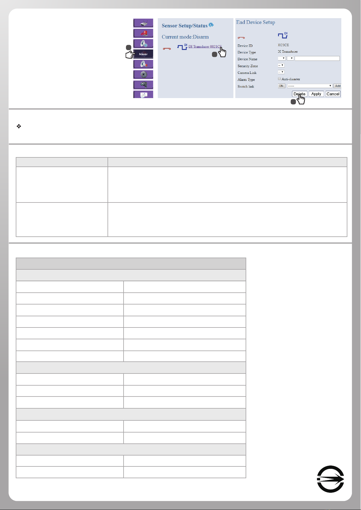
III. Device Deletion (Back to factory default settings)
1. First, Login into website.
About Login methods, please refer to 4.Basic Setting of Installation in Wireless Gateway Installation Guide. (Page1).
2. To remove the device joining, take out the battery, long press SET button 10 seconds. (Please Turn Over)

Notice
Design for monitoring the third party industrial detector status via DI/DO (dry contact) digital signal.
Troubleshooting
Problem Solution
Specifications
Wireless DI Transducer
a. Make sure the battery power is adequate and wires’connections are properly connected.
b. Reset to factory default (Please see Installation,III. Device Deletion), and re-join to the
system.
c. If the problem persists, please contact your local distributor.
Check the wireless signal via RSSI and the distance between device and Gateway/Router
(line of sight) is 200 meters (max.). If there is any obstructions (i.e. walls or metal objects)
between the devices, the distance will be shorter. Users can move the device closer or add
a Router, then try again.
Electrical Specications
Communication Protocol / Frequency
Operation Range
Operating Voltage
Battery Type
Battery Life
Input Signal
LED Indicator
Environmental Requirement
Operating Temperature
Storage Temperature
Humidity
Mechanical Specications
Dimension (W x H x D)
Weight (without battery)
Wire Assignment
Wire 1- (Red)
Wire 2- (White)
Zigbee Pro ZHA1.2 / 2.4 GHz ISM band
Up to 200 meters (LOS)
3 VDC
CR123A x 1
Up to 1 year
Dry contact x 1
Red
0°C to 40°C
-20°C to 70°C
90% RH Max., Non-Condensing
71.9 x 48.8 x 21.5 mm
32g
Dry contact Input (Positive)
Dry contact Input (Negative)
Installation (Continue)
III. Device Deletion (Back to default settings)
3. Delete the device from the website.
(See the features on the right side.)
4. Long press the SET button at the
back of the device. The LED indicator
blinks red and then turns o. After
6 seconds, the LED indicator blinks
red, indicating the deletion process
is sucessful. (Please complete the
procedure in 3 minutes.)
1
2
3
Note: After device deletion, it will back to auto joining mode.
The LED indicator lights
abnormally when linking to
the system
Cannot link to the system

Federal Communications Commission (FCC) Statement
15.21
You are cautioned that changes or modifications not expressly approved by the part responsible
for compliance could void the user’s authority to operate the equipment.
15.105(b)
This equipment has been tested and found to comply with the limits for a Class B digital device,
pursuant to part 15 of the FCC rules. These limits are designed to provide reasonable protection
against harmful interference in a residential installation. This equipment generates, uses and can
radiate radio frequency energy and, if not installed and used in accordance with the instructions,
may cause harmful interference to radio communications. However, there is no guarantee that
interference will not occur in a particular installation. If this equipment does cause harmful
interference to radio or television reception, which can be determined by turning the equipment off
and on, the user is encouraged to try to correct the interference by one or more of the following
measures:
-Reorient or relocate the receiving antenna.
-Increase the separation between the equipment and receiver.
-Connect the equipment into an outlet on a circuit different from that to which the receiver is
connected.
-Consult the dealer or an experienced radio/TV technician for help.
This device complies with Part 15 of the FCC Rules. Operation is subject to the following
two conditions:
1) this device may not cause harmful interference and
2) this device must accept any interference received, including interference that may cause
undesired operation of the device.
FCC RF Radiation Exposure Statement:
1. This Transmitter must not be co-located or operating in conjunction with any other antenna or
transmitter.
2. This equipment complies with RF radiation exposure limits set forth for an uncontrolled
environment. This equipment should be installed and operated with a minimum distance of 20
cm between the radiator and your body.
Other UIS Transducer manuals