manuals.online logo
Brands
  1. Home
  2. •
  3. Brands
  4. •
  5. UL
  6. •
  7. Indoor Furnishing
  8. •
  9. UL Motorized User manual

UL Motorized User manual

Popular Indoor Furnishing manuals by other brands

Regency LWMS3015 Assembly instructions

Regency

Regency LWMS3015 Assembly instructions

Furniture of America CM7751C Assembly instructions

Furniture of America

Furniture of America CM7751C Assembly instructions

Safavieh Furniture Estella CNS5731 manual

Safavieh Furniture

Safavieh Furniture Estella CNS5731 manual

PLACES OF STYLE Ovalfuss Assembly instruction

PLACES OF STYLE

PLACES OF STYLE Ovalfuss Assembly instruction

Trasman 1138 Bo1 Assembly manual

Trasman

Trasman 1138 Bo1 Assembly manual

Costway JV10856 manual

Costway

Costway JV10856 manual

moss DESIGN Caisson Credenza Assembly instructions

moss DESIGN

moss DESIGN Caisson Credenza Assembly instructions

Aquaglide FULL DECK 15.0 owner's manual

Aquaglide

Aquaglide FULL DECK 15.0 owner's manual

AREBOS AR-HE-SW30 user manual

AREBOS

AREBOS AR-HE-SW30 user manual

Till-Hilft Fulda 87005.330 Assembly instructions

Till-Hilft

Till-Hilft Fulda 87005.330 Assembly instructions

Twoey Outside 2010 quick start guide

Twoey Outside

Twoey Outside 2010 quick start guide

Hettich Easys 200 operating instructions

Hettich

Hettich Easys 200 operating instructions

The bedboss RELAX 404 Series owner's manual

The bedboss

The bedboss RELAX 404 Series owner's manual

Oeseder Möbelindustrie Bern 991 720 Assembly instructions

Oeseder Möbelindustrie

Oeseder Möbelindustrie Bern 991 720 Assembly instructions

Costway HW68469 user manual

Costway

Costway HW68469 user manual

Next ALIX A27743 Assembly instructions

Next

Next ALIX A27743 Assembly instructions

BROSA Hans Assembly guide

BROSA

BROSA Hans Assembly guide

Prodigg MINIKA PBA015T-FUR installation manual

Prodigg

Prodigg MINIKA PBA015T-FUR installation manual

manuals.online logo
manuals.online logoBrands
  • About & Mission
  • Contact us
  • Privacy Policy
  • Terms and Conditions

Copyright 2025 Manuals.Online. All Rights Reserved.

p. 1
Motorized
Roll Shutter Installation Guide
8 Step Installation Process
1.) Prepare Opening & Tools
2.) Install Tips
3.) Mount Build-Out & Guide Rail Assembly
4.) U-Sill, L-Sill or No-Sill
5.) Install Hood Assembly
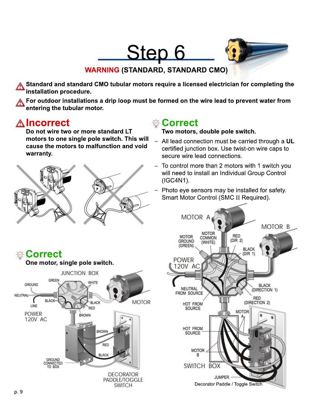
6.) Motor Wiring Diagrams (RTS, Standard, CMO)
7.) Set Limits & Install Shutter Curtain
8.) Finalize Installation & Customer Inspection (inform end user of correct operation instructions)
Before beginning please check that shop drawing dimensions match your current project
specification.
(See Opening Measuring Instructions for details)
Installation, servicing and repairs should be performed by a qualified and trained technician.
Please read through the entire guide thoroughl
Please read through the entire guide thoroughly, before proceeding with installation. Security
Shutter Ltd. will not be held responsible for any property damage or charges incurred due to
improperly installed shutter components. The following instructions will not alleviate you from
complying with local building codes and ordinances.
Disclosure
Ensure shutter installation does not interfere with federal, provincial or municipal building codes, safety Ensure shutter installation does not interfere with federal, provincial or municipal building codes, safety
or fire regulations or other restrictions or code that may apply. Security Shutter Ltd. will not be held
responsible for any injury or death from improper installation, application or use of provided shutters.
Think ahead
Important Install Tip
Risk of product damage (handle with care)
Risk of personal injury:
- Motorized operation
- Electrocution / Fire hazard
- Heavy curtain
- Sharp edges
- Pinch points
- Follow safe working practices
- Heavy lifting may cause bodily harm
- Oversized shutters require 2 or more technicians for safe installation and transportation
- Do not climb or stand underneath the shutter system
- The shutter should only be operated when in view
p. 2
p. 3
Step 1
Prepare Opening & Tools
Pliers
Wire strippers and crimper
Electrical tape
Electrical twist-on wire caps
Robertson #2 Bit
Long Philips Bit
Level (Preferably 4')
Pencil
Tape measure
Caulking gun and outdoor silicone sealant
(Best suited for the project.)
Drill with masonry settings
Optional; Rivet gun + (1/8”), (5/32”) &/or
(3/16”) SS/Aluminum rivets.
Drill bits for substrate. Concrete, wood or
metal. (1/8”), (5/32”) &/or (3/16”)
UL Certified junction box
Conduit
Knife
Safety glasses
Microfiber cloth
Mild Detergent (ex. 409)
2 or more people for assistance
On taller openings you may need a ladder,
scaffold, etc.
Necessary fasteners and driver bit best suited for
your project.
EX.
#10 Wood Screws
T
Tapcon Concrete Anchors
5 mm (3/16”) Metal or Masonry Drill Bit
5 mm (3/16”) &/or (1/4”) Driver Bit
(2.1) The opening structure must be adequate to accommodate the weight of the shutter system.
Surfaces should be plumb and smooth to guarantee a parallel alignment of the guide rails. It is
important that you check that the lintel does not bow inwards or have any protrusions that could
push the hood assembly out of alignment. Check that the shutter will not interfere with any opening
doors, windows, protruding door handles, etc.
(2.2) Unbox and inspect all shutter system components, including hardware bag before shutter
installation occurs. (Do not place shutter components on rough or rugged surfaces.)
(2.3)
(2.3) Mark and drill wire lead hole before installing any shutter components.
DO NOT CUT MOTOR WIRE LEAD WITHIN 30cm (12”) OF THE TUBULAR MOTOR
This will damage the antenna which is incorporated into the lead.
p. 4
Step 2
Install Tips
(2.5)
Remove
protective
foil from
areas that
will be
inaccessible
after
after
installation
process is
complete.
(2.4) To prevent damage and for ease of
access remove front 45° hood assembly
cover (#2 Robertson screws).
(2.6) For in-jamb application with no
overhead clearance place hood assembly
top-down & seat both guide rails firmly onto
both end cap legs located at the bottom of the
hood assembly. Then with assistance, gently
flip & lean the now attached guide rails &
hood assembly into the opening. Be sure to
support the shutter so as to not kink, twist or
bind hood assembly. Risk of product damage
(handle with care).
(2.7) For surface mount application with no
overhead restriction, level and fasten the guide
rails onto the opening before setting hood
assembly into the guide rails. (This will require a
minimum of 50mm ( 2” ) of overhead clearance
above the height of the hood assembly).
HTF & HTF-40 guide rails
are interchangeable.
V40-N has an extra 3mm
(1/8”) of build-out
thickness.
HTF-Secure has an extra
3mm (1/8”) of build-out
thickness and is not
interchangeable. Must be
mounted with protective foil
side inline with the front of
the hood assembly.
p. 5
Step 3
Mount Build-Out & Guide Rail Assembly
(3.3) If build-out is applicable, level & fasten
with unprotected side facing the wall in the
following order:
1.)
1.) Vertical build-out with guide rails. Fasten
bottom & second down mounting hole from
the top (this will allow room for minor
adjustment). If the floor is sloping you must
install the high side first.
2.) Horizontal top, bottom and sill build-out.
(3.1) Build-Out Standard Locations:
Left Guide Rail (pre-drilled & attached)
Right Guide Rail (pre-drilled & attached)
Mullion Guide
Hood Assembly Top
Hood Assembly Bottom
Sill
Sizes:10mm / 20mm / 30mm / 40mm / 50mm
(3.2) Proper mounting of build-out is subject
to adjacent structure location and condition.
Ensure that fasteners are long enough to
sufficiently penetrate mounting surface for a
secure mount. Some build-out components
do not come pre-attached and will require
independent mounting. Reference shop
drawing for further information.
p. 6
Step 3
Mount Build-Out & Guide Rail Assembly
Step 4
U-Sill, L-Sill or No-Sill
(3.6) Level guide rails plumb & parallel with
unprotected side facing the wall. If the floor is
sloping you must fit the higher side first.
(3.7) Fasten guide rail’s second down from
the top (#1, #2) & bottom (#3, #4) mounting
holes (this will allow room for minor
adjustment).
U - Sill L - Sill L - Stop
(4.1) Adjust bottom width of the guide rails to
the length of the sill to assure optimal shutter
operation.
L-Sills are provided and mounted to the total
outside width of guide rails.
U-Sills are provided and mounted to the interior
span between the guide rails. Drill adequate
weeping holes for water drainage if necessary
(use level to determine).
For No-Sill applications L-Stops will be provided
(installation is optional and dependant on
application).
(3.4) Measure the hood assembly length.
This will give you outside of guide rail to
outside of guide rail dimension.
(3.5) Place marks on the opening where your
guides will line up.
p. 7
Step 5
Install Hood Assembly
(5.1) 60mm/70mm axles have an adjustable
shaft on the opposite side of the motor.
Check set screw before attaching the hood
assembly.
(5.2) Feed the wire lead through the hood
assemblies's exit port grommet.
(5.3) With assistance feed wire lead through
previously drilled exit hole in the opening and
mount hood assembly by inserting end cap
legs into the guide rails.
(Pinch Points)
(5.4) Verify level, plumb & square, adjust
mounting holes (#1, #2, #3 & #4) to achieve
desired fit. Complete fastening guide rails
ensuring that top fasteners secure hood assembly
to the opening and the guide rails.
(5.5) For specific commercial or oversized
applications you will need to secure hood
assembly to the structure behind. Use
30x30mm L-angle or flat-washers as backing
to secure evenly along the edges every
30-60 cm.
p. 8
Step 6
Motor Diagrams (RTS, RTS CMO)
(6.1) Make the appropriate wire connections
for the tubular motor.
RTS tubular motors are fast and easy to
install. 3 wire Lead (Hot, Neutral, Ground)
RTS motor lead with a 120V wall plug can be
supplied at extra cost, (plug in any 120V wall
socket, no electrician required).
Limits are set with any Somfy
Limits are set with any Somfy RTS Remote /
Keypad / Smoove.
CMO
CMO tubular motors come in both RTS (3
wire) & Standard (4 wire). Crank Manual
Override does not interfere with the motors
limit settings allowing both manual and
electrical operations to function separately.
Main purpose of a CMO type motor is to
allow end-user to operate the shutter in case
of power outage.
of power outage.
DO NOT CUT MOTOR WIRE LEAD WITHIN 30cm OF THE TUBULAR MOTOR (12”)
This will damage the antenna which is incorporated into the wire lead.
LT50/60 ALTUS RTS
LT50/60 RTS CMO
GREEN
Crank
Manual
Override
Battery backup available from tubular motor
manufacturer only. Refer to Somfy specifications.
https://www.somfysystems.com
GREEN
WHITE
WHITE
BLACK
BLACK
p. 9
Step 6
Standard and standard CMO tubular motors require a licensed electrician for completing the
installation procedure.
For outdoor installations a drip loop must be formed on the wire lead to prevent water from
entering the tubular motor.
WARNING (STANDARD, STANDARD CMO)
Incorrect
Do not wire two or more standard LT
motors to one single pole switch. This will
cause the motors to malfunction and void
warranty.
Correct
Two motors, double pole switch.
All lead connection must be carried through a UL
certified junction box. Use twist-on wire caps to
secure wire lead connections.
T
To control more than 2 motors with 1 switch you
will need to install an Individual Group Control
(IGC4N1).
Photo eye sensors may be installed for safety.
Smart Motor Control (SMC II Required).
Correct
One motor, single pole switch.
Decorator Paddle / Toggle Switch
p. 10
Step 6
(6.2) Make the appropriate wire connections
for the tubular motor.
STANDARD tubular motors are to be
hardwired inline with your house’s breaker
box and light switch circuits.
Limits are programmed by depressing
push-button limits by the end cap motor
mounts. Push in yellow and white button to
set.
CMO
CMO tubular motors come in both RTS (3
wire) & Standard (4 wire). Crank Manual
Override does not interfere with the motors
limit settings allowing both manual and
electrical operations to function separately.
Main purpose of a CMO type motor is to
allow end-user to operate the shutter in case
of power outage.
of power outage.
Standard and standard CMO tubular motors require a licensed electrician for completing the
installation procedure.
LT50/60 LT50/60 CMO
Motor Diagrams (STANDARD, STANDARD CMO)