ULPOWER 260 series User manual

Interactive
Troubleshooting Guide
Version 2.0
Click an engine or scroll to next page to continue

Contents:
Instructions
Before first start checks
Trouble shooting guide

Welcome to the ULPower troubleshooting guide 2.0
The first section covers ‘procedures to follow before first start’ this is a reminder for those who are not yet ready to
start –to make sure that they have covered the basics. Your particular installation may vary slightly, and we refer you to
your engine and OEM installation guides for further details.
Please keep in mind that your engine has been fully tested at factory before shipment.
The Troubleshooting guide starts immediately after and is linked between topics. You may always return to the
‘Troubleshooting Start Page’ for troubleshooting by clicking on the ULPower logo on the top right of each page.
You may also simply ‘scroll’ through the guide. If you are using this guide on a mobile phone or tablet you may need to
download the Adobe Acrobat Reader to enable the links.
This document is provided as a guide. Please let us know if you find any errors or provide ideas for improvement.
The abbreviation “i.a.w. … manuals” means ‘in accordance with… manuals”
Please ALWAYS cross check with the latest installation, maintenance , operating manuals, available from
http://ulpower.com
Regards
The ULPower Team (email info@ulpower.com ) E&OE Mar 2019

BEFORE FIRST START:
During installation consult and work i.a.w. the various
installation manuals
1. Battery/Oil:
Check if the battery is fully charged and oil level is sufficient
2. Calibrate senders/sensors:
Oil temperature, EGT and CHT senders using boiling water
(100°C/ 212 F)
3. Check the Fuel System with a fuel flow test:
Disconnect return line and put into measuring jug
Run pump 1, collecting fuel
Measure fuel flow coming out of the return line +/- 120 l/h or 1
liter(quart) in 30 seconds
Repeat for pump 2
Reconnect lines and check fuel pressure (+/- 3.3bar/49psi)
(without starting the engine)
4. Check ECU warning light:
Power ON to ECU
UL check light should NOT light up
Disconnect Air box temp sensor –if working, the UL check light
comes on. Reconnect sensor –light goes off.
5. Start-up routine with COIL checks
•Ignition coils : set coil 1 ON / coil 2 OFF
•Throttle max 30% open (normally cracked open)
•Safety check –area clear and shout ‘clear prop’
•Master ON
•Main Fuel pump selected ON
•ECU ON
•Activate ‘Start’ - max 5 sec –wait 15 sec - repeat max. 4 times
•Engine should be running. Wait 15+ seconds, stop engine (ECU OFF)
•Repeat with coil 1 OFF / coil 2 ON. Wait 15+ seconds, stop engine
•Repeat with coil 1 ON / coil 2 ON. Leave engine running
6. Other first start checks
•If possible connect with ULread .
•Visual check for oil leaks / fuels leaks / mechanical interference
•Measure oil pressure and to check with instruments/readout
•Run the engine at +/- 1200 rpm until oil temp. is 60°C (140°F)
•Shutdown (switch ECU OFF, Fuel pump OFF, coil 1 OFF , coil 2 OFF
Master OFF
•Adjust idle if necessary
•Allow engine to cool and ‘finger test’ for oil leaks.
7. Running in: Avoid full throttle (max 2800rpm) for the first 10 hours

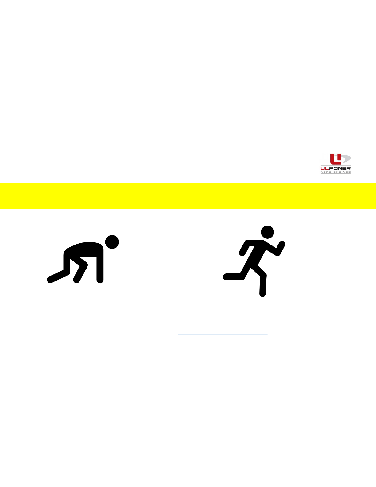
What to do if your engine won’t start or runs rough?
at first start after first start
TROUBLESHOOTING STARTS HERE
Remember to always work i.a.w. the latest manuals. If you are unsure of what action to take or unable to resolve your
problem, contact your local ULPower Aero Engine dealer http://ulpower.com/en/dealers

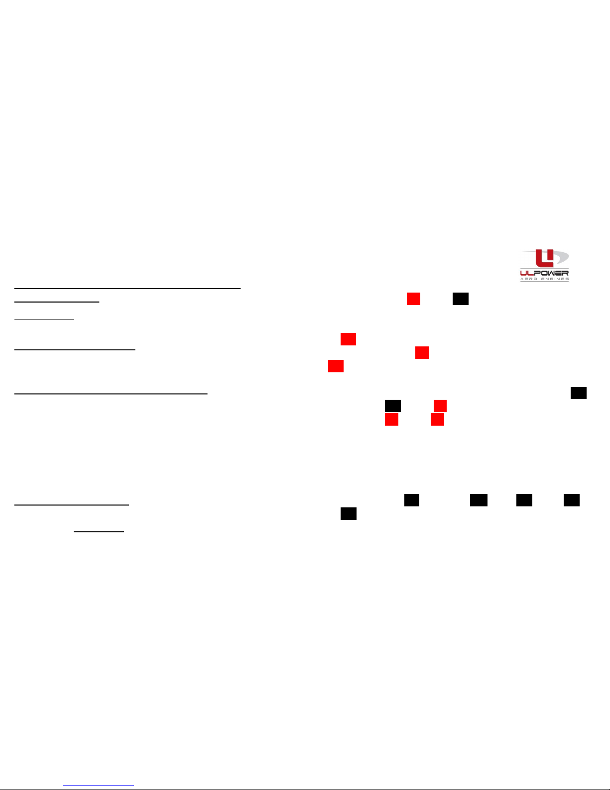
Trouble shooting when your engine fails to
start at FIRST START
Start button,
Grounding &
ECU
connection
Ignition
cables
Fuel
system
Sparkplugs Coils ECU Wiring
loom
Injectors
Click text or the image above for an aspect you suspect –or, if
unsure follow the sequence from left to right...

Start button, Ground cable & ECU connection
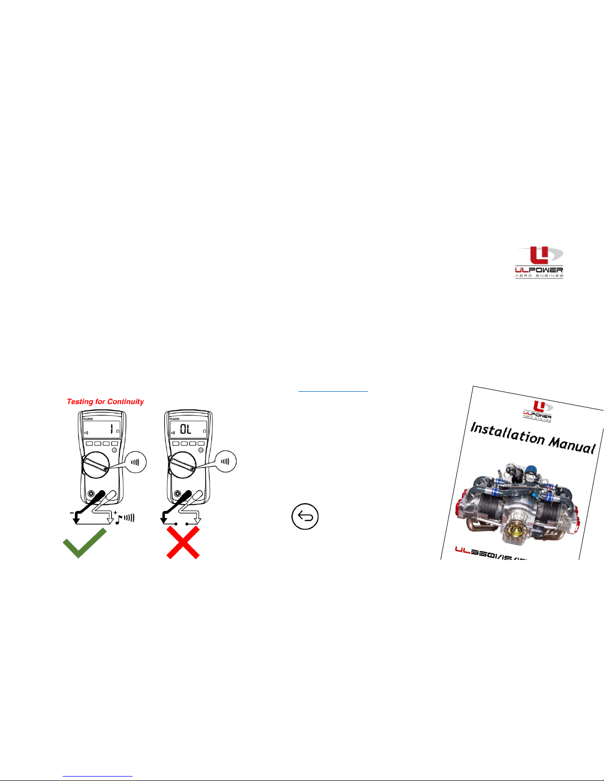
1. Check that the start button closes the circuit to the starter relay –disconnect at starter relay and check
using continuity on a multimeter. Reconnect if good.
2. Visually check for presence and connection of ground cable between the engine and the airframe.
3. Check using a multimeter check for ‘continuity’, i.e. that there is no break from engine to the negative
terminal on the battery. This may require sequential readings, depending on the installation.
4. Check both ECU connectors are connected and that all wires are routed and connected i.a.w. the latest
installation manual for the engine. (available from ULPower.com )

Ignition cables
Check the ignition cables and connections
•Make sure that both connectors (coil side and spark
plug side) are installed i.a.w. the installation manual. If
not installed properly, no contact or an incorrect contact
may occur.
•To check if the connectors are installed properly, pull
fairly hard on both ends of the ignition cable.(coil side +
sparkplug side). The connectors will remain in place if
installed correctly. If they break free –REMAKE THE
CONNECTION
•Check if both connectors from the wiring loom are well
connected/seated to the coil
•For 4 cylinder engines (260 and 350 series) make sure
that the supplied aluminium coil bracket is installed.
(Omitting the coil bracket may result in a deformed coil
with loss of contact inside the coil.) 4 cylinder coils require the aluminium
brackets for correct operation
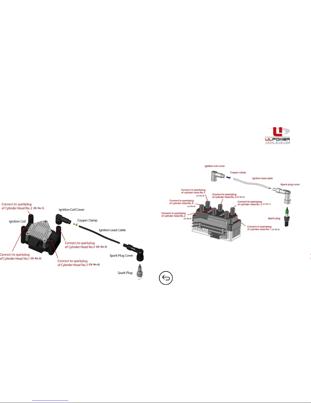
Ignition cables
Check HT cable orientation (are HT cables correctly installed between cylinders/spark plugs and coils)
4 Cylinder
260/350 series
6 Cylinder
390/520 series
NOTE: for RR engines see relevant installation manuals
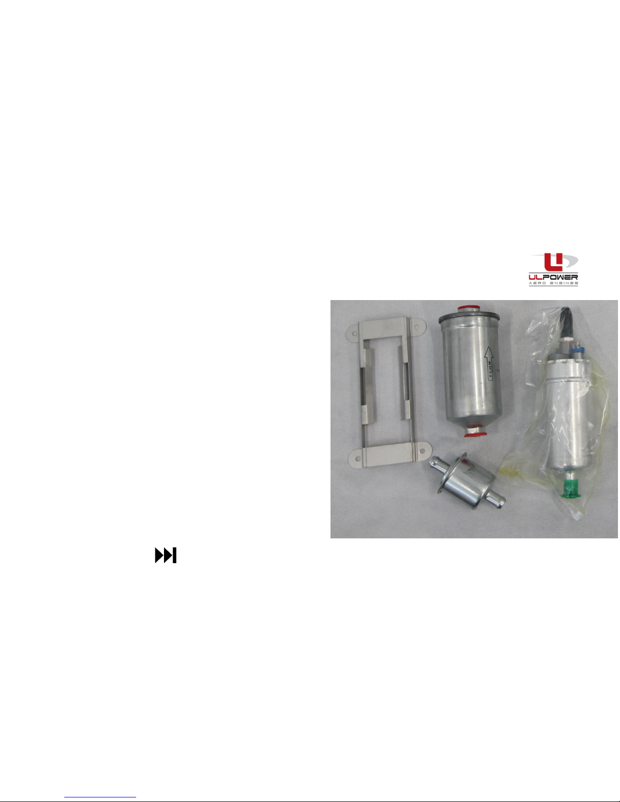
Fuel system
UNDERSTAND THE INSTALLATION
Normally two fuel pumps are installed, at times only one
is installed. CHECK before continuing.
Depending on the installation, the main and/or auxiliary
fuel pump may be commanded by the ECU via a relay.
Depending on the installation there may be a DPST
switch to select pumps and/or an ‘over-ride switch’.
UNDERSTAND THE INSTALLATION YOU ARE WORKING ON
BEFORE TROUBLESHOOTING.
Fuel Pump Control Relay (FPCR)
With the FPCR is fitted, when switching the ECU ON: the
FPCR protected pump(s) run(s). If the engine is not
started, the ECU will switch off the FPCR protected
pumps after 15 seconds. If this is part of your installation
–CHECK it functions correctly.

Fuel system (cont...)
Check the fuel pressure –if no/insufficient pressure then:-
1. Can you hear the pump(s)? If not, check the electrical connection –use a multi-meter on ‘DC’ setting if
necessary. If yes, check if they run in the right direction. (wiring direction “+” and “-”)
2. Is there FUEL to the Pumps? Check fuel taps and that check valves are correct –and that fuel is in the
selected tank. Check for blockages/restriction in the lines (kinks, collapsed lines etc)
3. Do you have the right fuel lines? You need 1/2“/12mm I.D. lines (-8) to the pumps to ensure sufficient
volume at the intake.
4. Are you sucking air? Check pick-up points in the tanks and no weak spring drains that allow air to be sucked –
if necessary provide fuel from a slave tank to test flow.
5. Are you sure your instruments reading correctly? To check pressure install a second analogue manometer in
the fuel line. (Ask your agent for the ULP oil and fuel pressure trouble shooting kit T080001)
6. Are the filters blocked? Check pre-pump and fine post-pump filters for blockage, replace if necessary.
7. Check return line is not compromised or closed off NOTE: min 1/4”/6.35mm (-4), ideally 3/8”/9.5mm (-6)
8. Pressure Regulator? There might be a fuel pressure regulator problem (please contact your ULP agent)
TO SEE FUEL FLOW CHECK CLICK HERE

Spark plugs
How to check the spark at the plugs
•For safety reasons: always disconnect the fuel pump before running this test
•For both coils : put switch TO ON
Method 1:
•Remove 1 sparkplug and hold the spark to the “ground” (or use a new spark plug)
•Engage starter engine
•Check if there is a spark. CAUTION HIGH VOLTAGE!
NOTE: You may not see the spark in bright sunlight (shield it for better visibility)
Method 2 (preferred method)
•Install a ‘HT ignition lead spark tester’ unit between the boot and the spark plug
(you may install 4 to see all at once)
ACTION?
•If there is NO spark, go to COILS If there IS a spark, go to INJECTORS

Coils
Check for a short-circuit in the wires to the coil switches
•Switch both ignition switches to ON (ie OPEN
circuit) alternatively disconnect wires from
switches.
•Master ON and ECU ON (NOTE ENGINE IS LIVE)
•Using a multi-meter (set to DC volts) Measure
voltage between “ground” and “control signal
wire” – see right.
•If you have 0v , there is a short-circuit between
ground and control signal wire in the wiring
loom. Check/correct/replace wiring.
•If you have 9v go to ECU troubleshooting
White/
White
Control
signal
coil 1
White/
Red
Control
signal
coil 2
White/
Blue
GROUND
Ign.Switch
Coil 1
Ign.Switch
Coil 2

ECU (Engine Control Unit)
Check ECU supply voltage
The ECU needs at least 10V (even during cranking) to function. If your battery is faulty or not fully charged, the
ECU will not boot and remain active –consequently there will be no spark and no injector signal.
Using a multi-meter set to DC Volts, measure the voltage at the battery terminals (min. 12 V)
•If not ok , change battery and try to start engine again.
•If ok , disconnect both coils for safety reasons. Master ON and ECU ON (NOTE ENGINE IS LIVE)
Measure voltage between “+” and “-“ on the ECU wiring loom coming from the cockpit.
TIP: Ideally use a Multi-meter which will record minimum voltage.
Engage the starter of the engine and check for voltage drop to the ECU.
If the voltage drops below 10v during cranking, relocate battery closer to the engine and/or use
larger section wires. (see installation manual for more details)
12.85

Cockpit Wiring
How to check a possible wiring problem on the cockpit side
Instruments or bad wiring in the cockpit can disturb the ECU
Either
Use the ULPower TROUBLE SHOOTING WIRING LOOM (T08003) by removing the
small connector from the ECU and replace with the troubleshooting loom
or
•Disconnect ALL wires from the Ecu-cockpit harness
•Insulate all wires (green, browns, grey yellow), white shrink sleeve to avoid
contact with each other or ground.
•Use a separate fully charged battery (do not connect two batteries together)
•Connect the blue shrink sleeved wire to the battery NEGATIVE (-) side
•Connect the red shrink sleeved wire to the battery POSITIVE (+) side
Then (NOTE ENGINE IS LIVE)
Try to start the engine. If the engine starts, the problem is in the cockpit side.
Check/correct/replace wiring as necessary.
If engine is still not starting, consider replacing the coils
Troubleshooting wiring loom T08003

Injectors
How to check if the injectors work
•Use the ULP injector trouble shooting kit (T080002) (shown right)
•For safety reasons : disconnect both connectors from the coils
•Disconnect a connector from the injector on cylinder 1.
•Connect the trouble shooting kit
•Master ON and ECU ON (NOTE ENGINE IS LIVE)
•Keep the additional injector close to your ear.
•Engage the starter of the engine
•Listen to hear “click – click –click”
•If no : it means that there is no signal coming from the ECU or damaged
cable/loom –try another injector…
•If yes : there is a signal coming from the ECU.
•The installed injector is possibly blocked and may have to be replaced.
If you have been through all of the above steps and still cannot identify the issue, contact your ULPower dealer .

Troubleshooting after first start
RPM Black Smoke, High Fuel
Consumption, Sooty plugs
Oil Pressure Oil Temp Oil Leaks/
consumption
Loss of
Compression
Detonation Fuel Pump
failure
CHT
variations
EGT
variations
Regulator/
Voltage
drops
ULP Check
Light
CHT EGT

RPM
What if your engine runs out of control/ RPM unstable
DOES THE ULP CHECK LIGHT COMES UP ?
If yes, find out with ULRead which sensor is causing it. Check connections,
Identify and replace the sensor/connector or repair/replace loom if damaged. Test again.
If not, continue below
CHECK THROTTLE CABLE
As per the installation manual, the throttle cable should never be installed ‘taut’ or
‘tight’ from the engine to the firewall. Always install it with some slack. (see IM)
NB: If the throttle cable is installed under tension, the ECU may consider the engine
movement (caused by vibrations pulling and releasing the throttle cable very small
amounts) as a ‘request’ for continuous acceleration and therefore an increase in fuel
injection, resulting in a rough running engine and/or black smoke.

CHECK FOR ‘FALSE’ AIR/COLLAPSED LINES/OTHER SUCTION SIDE ISSUES
If the cylinder can suck air into the fuel system, or any other aspect of the fuel/air system that can affect mixture occurs it will
cause inconsistent RPM readings. (increase/decrease):-
•Inspect the small hose between the airbox/manifold and the fuel pressure regulator for fit/damage.
•Check the same hose banjo eye at the airbox/manifold for torque/connection.
•Check torque on the two M6 bolts at manifold inlet tubes at each cylinder head
•Remove the air filter and check if both screws and throttle axle are still in place
•Check fuel line size, routing, condition and connections are i.a.w. manuals
•Ensure that the fuel return line is free of obstruction (check valve not stuck/incorrectly installed)
•Check filters
•Check for condition/fit of sensor connectors on airbox/manifold
•Check that fuel drains/seals are not allowing air to enter the system (eg Gascolator?)
•Check fuel tanks are not unported (the pick up pulling air from the tanks)
•Check fine screen on Pressure regulator (note only for advanced users)
•See here for more ideas
RPM

Black smoke / black spark plugs / high fuel consumption
•TPS (THROTTLE POSITION SENSOR) PROBLEM
If the TPS values are between 0.3 V (throttle closed) and 4.7 V (Wide Open Throttle) but the sensor is not working
properly, resulting in an incorrect fuel/air mixture.
•INLET AIR TEMPERATURE SENSOR (ATS) PROBLEM
If the ATS values are reading between -20°C and +80°C the check light will not come up. However, if the sensor is not
working properly (reading an incorrect temperature) the fuel/air mixture will not be correct.
•OIL TEMPERATURE SENSOR (OTS) PROBLEM
If the OTS values are reading between -30°C and +140°C the check light will not come up. However, if the sensor is not
working properly (reading an incorrect temperature) the fuel/air mixture will not be correct.
DOES THE ULP CHECK LIGHT COMES UP ?
If yes, find out with ULRead which sensor is causing it. Check connections.
Identify and replace the sensor/connector or repair/replace loom if damaged. Test again.
If not, continue below for ‘sensor faults that may not cause a ULP check light’
This manual suits for next models
3
Table of contents
Other ULPOWER Engine manuals
Popular Engine manuals by other brands

Parker
Parker GVM Series Technical manual

Komatsu
Komatsu 95-2 Series Shop Manual

ACM
ACM TITANSIDE installation manual

NGH
NGH GF60i2 Operation & instruction manual

Predator Engines
Predator Engines Pacific Hydrostar 212cc Gasoline Powered Clear Water... Owner's manual & safety instructions

Kohler
Kohler Courage XT-6 owner's manual