Vman C07 Series Technical manual

!
Technical Document
C07 Series
2021
6

Technical Documentation
1
VMAN ENGINE
01
03
03
04
05
07
08
08
08
09
09
11
12
12
13
13
14
17
17
26
27
27
0. To Users and Operators
1. Safety procedures & Diesel engine specification
1.1 Safety Procedures
1.2 Diesel engine specification
1.3 Diesel engine model, order number and series number
1.4 Assembly
2. Engine Operation instruction
2.1 Fuel
2.2 Oil
2.3 Coolant selection
2.4 Engine Start
2.5 Engine Operation
2.6 Engine Shutdown
2.7 Running-in of a new or overhauled engine
3. Engine Maintenance
3.1 Maintenance Schedule
3.2 Tasks and Methods of Engine Maintenance
4. Troubleshooting Guidelines
4.1 Troubleshooting Guidelines
4.2 Injection pump timing check and adjustment
5. Engine storage
6. Processing Requirements For Handling Quality Problems
Table of Contents

Technical Documentation
2
VMAN ENGINE
TO USERS AND OPERATORS
Thank you for purchasing a diesel product of VMAN ENGINE.
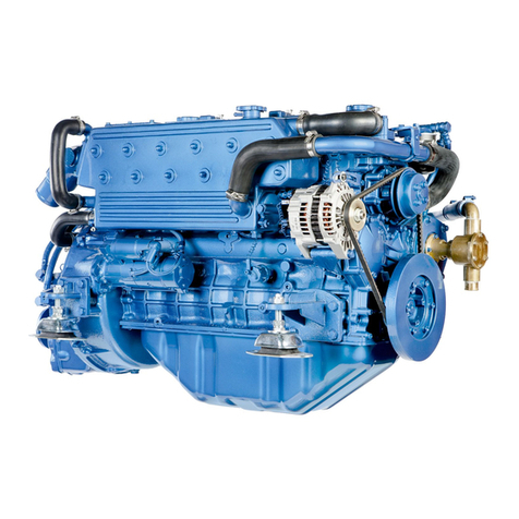
The C07 series diesel engine, is a medium-power four-valve diesel engine with six cylinders that is newly
developed by VMAN Company. Featuring strong power and low fuel consumption and with the emissions
conforming to relevant national regulations, C07 series diesel engine is a ideal supporting power for the
middle- and high-end vehicles and industrial equipment.
The diesel engine will improve continuously, so the content described herein may not be the same product
you purchase. Any questions, please inquire our sales department. Please specify the diesel engine model,
order number and produce date so that we can serve you more efficiently. The manual will also be revised
and reprinted according to the diesel engine improvement.
Users should use fuel, lubricant and coolant properly according to this manual.
Users should use and maintain diesel engines according to this manual and keep maintenance records
regularly.
This manual should be delivered to new users along with diesel engine.
If you have any question or suggestion regarding this manual, please contact us.
Thank you.

Technical Documentation
3
VMAN ENGINE
D11 (V6) SERIES DIESEL ENGINE
1. SAFETY PROCEDURES& DIESEL ENGINE SPECIFICATIONS
1.1 Safety Procedures
1.1.1 Abstract
-In order to avoid errors and malfunctions during operation and maintenance, only professional workers
having a full knowledge of safety notes and warnings are allowed to operate.
-This abstract is a compilation of the most important procedures, which can be broken down into main
sections containing the information necessary for preventing injury to persons and damages to property and
pollution. In addition, diesel engine related local regulations are to be observed.
IMPORTANT: If despite all precautions, an accident occurs, especially for corrosive acid, fuel, sharp iron
fillings, hot oil and anti-freeze fluid sputtering into eyes, shall go to doctor immediately.
During start-up and running, any person or tool are not allowed to contact rotating parts!
During running or just stopped, skin and eyes are not allowed to touch extremely hot and corrosive
material like oil, coolant and waste gas!
During running or just stopped, fuel, engine oil, etc. must not be put close to flame, or on the diesel
engine surface.
For safe and stable operation, people authorized to operate and repair must have received special
training and abide by the procedures of this manual!
1.1.2 Operation cautions
-Before start up a new diesel engine, carefully read the instruction and clarify the model, specification as
well as maintenance and tool use requirements.
-Before start up an engine, carefully check the status of fuel, engine oil, coolant, battery charging, electric
parts and fuel injection control system, make sure everything is normal.
-When engine running normally, pay attention to working environment, make sure operating under a safe
circumstance. Frequent transit overspeed and overloaded operation are forbidden. Troubleshooting or
special tools shall be applied as per fault degree after engine stopped. Engine shall stop gradually after
Do not touch oil drain plug or oil filters with bare hands in case of scaldings.
Electrolyte is toxic and corrosive and battery gas is explosive, wherefore battery repair shall be performed
by professional and authorized people only.
Health precautions: Avoid prolonged or repeated skin contact with used engine oil. Protect your skin by
suitable hand creams or wearing protective gloves. Clean skin which has been in contact with engine oil
timely. After washing apply a fatty skin cream to the skin.Change oil-soaked clothing and shoes. Do not
put oily rags into your pockets.

Technical Documentation
4
RATINGS DEFINITION
The power ratings of Emergency Standby and Prime are in accordance with the
standard of IS08528. Fuel Stop power in accordance with the standard of ISO3046.
Electric power (kW) should be estimated by considering generator efficiency,
cooling fan power loss and power derating due to altitude and temperature.
STANDBY POWER RATING is applicable for supplying emergency power for the
duration of the utility power outage. No overload capability is available for this
rating. A standby rated engine should be sized for a maximum of a 70% average
load factor and 200 hours of operation per year, this includes less than 25 hours per
year at the Standby Power rating.
PRIME POWER RATING is available for an unlimited of hours per year in variable
load application. Variable load should not exceed a 70% average the Prime Power
rating during any operating period hours., The Total operating time at 100% Prime
Power shall not exceed 500 hours per year.
10% overload capability is available for a period of 1 hour within a 12 hours period
of operation. Total operating time at the 10% overload power shall not exceed 25
hours per year,
CONTINUOUS POWER RATING is the power that the engine can continue to use
under the prescribed speed and the specific environment condition in the normal
maintenance period stipulated in the manufacturing plant. And continuous power
applicable for supplying utility power at a constant 100% for an unlimited number of
hours per year. No overload capability is available for this rating.
COOLING SYSTEM
Water circulation by centrifugal pump on engine
Coolant capacity
9.6 L
Max.Permissible Temperature
90 ℃
Max.Coolant warning Temperature
95 ℃
Max.Coolant Shutdown Temperature
99 ℃
Thermostat Open Temperature
82 ℃
Max.external coolant system restriction
Not available
Two radiator options are provided, based on allowable maximum Air temperature On radiator inlet ( Air On 40 °C) Air On 50 °C
- ATB (Ambient Temperature before Boiling ) of generator set varies depending on the engine room ventilation design, even if the same radiator applied. Adequate selection of
radiator options by means of the cooling test is highly recommended, and generator set makers are responsible for the selection.
VMAN ENGINE
1.2 Diesel engine specifications
1.2.1 C07 series
GENERAL ENGINE DATA
Engine Model
C07A
C07B
Engine Type
6-Cylinder, Turbo charged & intercooled (air to air)
Prime Power ( kW/Ps )
170/231
180/244
Standby Power ( kW/Ps )
187/254
198/269
Continuous Power ( kW/Ps )
135/183
140/190
Speed
1500 rpm
1800 rpm
Bore x stroke
105*124 mm
Displacement
6.5 L
Compression ratio
16:1
Rotation {Looking at flywheel}
Counter clockwise {CCW}
Firing order
1-5-3-6-2-4
Injection timing
12˚±0.5˚ BTDC @ 1500 rpm
12˚±0.5˚ BTDC@ 1800 rpm
Dry weight {W/O cooling system}
600 kg
Dimension {L x W x H}
1330 * 789 *1079 mm
Flywheel housing
SAE 3 #
Flywheel
SAE (11-1/2) #
Number of teeth on flywheel
127
Piston speed
6.5 m/s
7.8 m/s
ENGINE MOUNTING
Max.Bending Moment at Rear Face to Block
1120 N.m
INTAKE & EXHAUST SYSTEM
Engine Model
C07A
C07B
Max.Intake Restriction (kPa)
6
6
Max.Exhaust Back Pressure (kPa)
<10
<10
Combustion Air Consumption (m³/h)
1126
1848
Max.Exhaust Temp.(After Turbo°C)
550
550
Exhaust Gas Flow (m³/h)
714
882

Technical Documentation
5
VALVE SYSTEM
Type
Overhead valve type
Number of valve
Intake 2, exhaust 2 per cylinder
Valve lashes at cold
Intake 0.25 mm, Exhaust 0.50 mm
Valve timing
Opening
- Intake valve
20.9 deg.BTDC
- Exhaust valve
51.7 deg.BBDC
C07 Series diesel engine drawing
VMAN ENGINE
FUEL SYSTEM
In-line pump with integrated, electromagnetic actuator
Engine Model
C07A
C07B
Governor
Electric type (Original GAC from USA)
Speed drop
G2 Class (ISO 8528)
Feed pump
Mechanical type in pump
Injection nozzle
Multi hole type
Opening pressure
25 MPa
Fuel filter
Full flow, Cartridge type with water drain valve
Maximum fuel inlet restriction
25 kPa
Maximum fuel return restriction
50 kPa
Fuel feed pump Capacity
450 liters / hr
Fuel
Diesel fuel
Fuel Consumption of generator set
Standby power- 100% load (l/h)
44.4
48.4
Prime Power - 100% load (l/h)
39.7
43.4
- 75% load (l/h)
29.5
32.8
- 50% load (l/h)
20.5
22.2
- 25% load (l/h)
11.4
12.6
Continous power - 100% load (l/h)
27.8
30.4
Lowest Fuel Consumption Ratio(g/kW.h)
205.0
215.0
LUBRICATION SYSTEM
Force-feed lubrication by gear pump, lubricating oil cooling water circuit of engine
Force-feed lubrication by gear pump, lubricating oil cooling water circuit of engine
Lub.Method
Fully forced pressure feed type
Oil filter
Full flow, cartridge type
Lube oil specification
CF-4
Lube oil pressure
Idle Speed : Min 80 kPa
Governed Speed: Min 200 kPa
Maximum oil temperature
115 °C
Max.Permissible Oil Temperature
98 °C
Oil Consumption (as % of fuel consumption)
≤0.2
Oil capacity
24 L
ELECTRICAL SYSTEM
Charging Alternator Voltage
28V
Charging Alternator Capacity
35A
Voltage regulator
Built-in type IC regulator
Starting motor
5.5kW
Battery Voltage
24V
Battery Capacity
2 * 120 Ah ( recommended )
Starting aid (Option)
Block heater ( Min. Temperature for Unaided Cold Start -10°C )

Technical Documentation
6
VMAN ENGINE
1.3 Diesel engine model, order number and serial number
The engine model and serial number are printed on the engine label.
These numbers are required when requesting warranty and ordering parts.
1.3.1 Diesel engine model
Power code: Using 1 ~ 9, basic model is not numbered
Development sequence code: represented by A, B, C…
Displacement, 7 represents displacement of 7L
Fuel form code: C represents “C”-inline type,
Example 1: C07A represents VMAN diesel engine, displacement of 7 L
Example 2: C07B represents VMAN diesel engine, displacement of 7 L
1.3.2 Diesel engine model
Diesel engine product order number and feature code are represented by Arabic numerals and letters, the
sequence is shown as below
Model configuration type: 01 ~ 99
Rated speedA says “1500r/min”
B says “1800 r/min”
ExampleA01 says 1500 r/min, first type of configuration.
1.3.3 Diesel engine nameplate
The diesel engine nameplate indicates the
main technical data and information: model,
order no., serial no., date of production,
rated power and rated speed, which are the
major basis for you to purchase service parts
and for VMAN to conduct after-sale technical
service. We hope you to put the information
and data into the daily record of work of your diesel engine or the matched devices for later repair and
reflection of quality problems, which are helpful to the correct settlement of your problems. The nameplate
locates at the top of the cylinder head coverProtect it from being damaged.

Technical Documentation
7
VMAN ENGINE
D11 (V6) SERIES DIESEL ENGINE
Part Name
1
Turbocharger
2
Valve Cover
3
Engine coolant outlet pipe
4
Left engine lifting plate
5
Fan bearing housing
6
Water pump
7
Alternator
8
Engine coolant inlet pipe
9
Tensioner
10
Oil filter
11
Fan Belt
12
Vibration damper
13
Water drain plug
14
Starting motor
Part Name
15
Intake pipe
16
High pressure fuel pipe
17
Right engine lifting plate
18
Front engine lifting plate (optional )
19
Fuel injection pump ( Electronic
speed governor )
20
Fuel injection pump fuel inlet pipe
21
Fuel filter inlet pipe
22
Fuel filter
23
Oil dipstick
24
Flywheel housing
25
Oil pan
26
Oil drain plug
1.4 Engine Assembly
1.4.1 Peripheral part name - engine intake side
Exhaust Side Front End
Intake Side Rear End
No
Name
Wrench dimension S (mm)
Tightening torque (N•m)
1
High-pressure fuel pipe nuts
19
35 (Injector end )
35 (pump end)
2
Banjo bolts to fuel return pipe of fuel injection pump
18
30-35
3
Banjo bolts to fuel- inlet pipe of fuel injection pump
18
30-35
4
Banjo bolts to fuel return pipe of fuel injector
16
25-30
5
Banjo bolts to inlet/outlet of fuel transfer pump
18
30-35
6
Banjo bolts to fuel filter inlet/outlet
16
25-30
7
Bleed screws on fuel priming pump
19
Until tightened
8
Oil pan drain plug
21
60
9
Valve clearance adjusting nuts
14
24
10
Valve clearance adjusting screws
5 (Inner hexagon)
11
Valve cover nuts
13
24
12
Bolts of cylinder head intermediate cover
10
24
13
Tensioner wrench jaw
1/2 inch
14
Fan clamp nuts
15
40
15
Water drain plug
8
45
1.5 Tightening Torque for Engine Parts

Technical Documentation
8
Hanma Power Supply, APICH-4 Viscosity Rating
Ambient temperature (℃)
Minimum
Highest
SAE0W20
-40
10
SAE0W40
-40
40
SAE5W40
-30
40
SAE10W30
-20
40
SAE15W40
-10
40
SAE20W50
0
50
Grades of fuel
0#
-10#
-20#
-35#
Cetane value
≥49
≥49
≥46
≥45
Solid point/℃
≤0
≤-5
-20
-35
Minimum applicable temperature
(engine working temperature)/℃
Above 4℃
Above -5℃
Above -14℃
Above -29℃
VMAN ENGINE
Caution: Fuel must be kept at the highest level of cleanness and not polluted by dust, impurities or water.
2. ENGINE OPERATION INSTRUCTION
Proper use of your engine can not only keep it in normal working order and good performance, but also can
extent its service life and reduce its use cost. Adopt proper fuel, oil and coolant, as well as the correct
operation steps stipulated in this section.
2.1 Fuel
The grade of diesel fuel should be determined based on the ambient temperature. In cold winter, fuel with
low-freezing-point should be adopted, while in the contrary in summer. The fuel used should be in
accordance with the GB 19147-2009, and the grade of fuel as per recommendations of GB/T 19147. You
may take the recommendations in the table below: e.g. the -35# fuel should be used at the ambient
temperature of -27℃.
Relationship between diesel fuel grades and applicable minimum temperatures
2.2 Oil
In order to ensure the normal operation of the engine, play the best performance, improve reliability,
improve the engine emissions, please use the VMAN engine dedicated to CH-4 grade lubricants and above
is strongly recommended for this engine in order to ensure its normal operation and long service life and
improve its emissions. If the above engine oil is not available, oil of CF-4 grade or above meeting the
requirements of American Petroleum Institute (API) can serve as an alternative.
Operating temperature range for engine oilGB 11122-2006
Caution: Engine oil must be kept clean and free from dust, impurities or water.

Technical Documentation
9
Matter in water
100Water
Chloride
50 ppm max.
Sulfate
50 ppm max.
Mineral saltlime carbonate
100 ppm max
soluble solid
250 ppm max.
PH value
6.5 or above
Freezing temperature
Glycol concentration
15℃
30
23℃
40
37℃
50
51℃
60
VMAN ENGINE
D11 (V6) SERIES DIESEL ENGINE
2.3 Coolant selection
Coolant with antifreeze function is required for the engine at any climate to ensure it normal operation and
service life. Coolant with antifreeze function can not only prevent itself from freezing in ambient condition
and also enhance its boiling point.
The coolant for the engine consists of water and glycol. The mixture of 50% water and 50% glycol is
recommended for most climates, and acceptable content of glycol in water is 40%-60%. The freezing point of
coolant is generally about 10℃below the lowest ambient temperature. The relation between content of
glycol in water and freezing temperature is as below.
Note: Before filling coolant into the engine, mix water and glycol to a certain ratio according to the table
above based on ambient temperature or get a right content mixture from market. The ice point of coolant
can be measured by special testing papers that are available in market.
Caution: Never use 100% glycol as coolant.
Water for coolant should be soft water or processed tap water. Do not use water from river, lake or sea or
unprocessed hard water. For water shortage areas, use boiling method or to base method to process well
water or underground water and take clean water abover the sedimentation. The water used for coolant
should meet requirements as below.
2.4 Engine Start
Before using the engine, choose proper engine oil, fuel and coolant according to actual ambient conditions.
Besides, the following work should be done before starting:
-Make a surround inspection of the engine and its starting system, and solve problems in time if any.
-Check oil pressure and temperature gauges, warning lights and other instruments for normality.
-Check the fault diagnosis indicator for normal working condition.
-Check the service indicator of the air filter for appearance of red piston.
Caution: Do not to start the engine without an air filter to avoid early engine wear.

Technical Documentation
10
VMAN ENGINE
-Check the oil level for being within the specified range.
-Check the coolant level for being within the specified range.
-Check the electrolyte level for being within the specified range.
-If the engine has not been in operation for a long time, or its fuel filter has just been replaced, there may
be air in the fuel system. Prime the fuel system with priming pump if necessary. Refer to section 4.3 for
specific priming operation.
-Check the electric starting lines for normality.
-All the safety devices must be installed in place.
-Check the accelerator pedal for free movement.
2.4.1 Normal starting procedure
-Disengage the engine from all driven equipment, or put transmission into the “neutral” position if equipped.
-Put the mechanical operating devices into the “running” position.
-Insert electric key and turn the switch from the position OFF to the position ON to electrify intake air heating
device and other electrical devices.
-Wait until the pre-heating indicator light goes out (the light flashes on when intake air pre-heating proceeds and
it doesn’t flash when no pre-heating happens). Then turn the switch from the position ON to the position START
to start the engine. For vehicle application, it is required to step on the accelerator pedal when starting.
Caution: Starting time should be no more than 15 seconds and there should be a 2-minute interval before the
next starting so as to prevent the damage to starting motor.
-Each starting usually lasts 2 -3 seconds.
-The switch goes back to the position ON from the position START automatically after starting up.
Caution: The oil pressure gauge should show reading within 15 seconds after the engine has successfully been
started; otherwise, stop the engine immediately to prevent damage to the engine and find the causes according
to Section 5 Troubleshooting Guideline.
-Started up from a hot state, the engine should run at idle for 1-3 minutes before being accelerated and loaded
gradually.
-Started up from a cold state, the engine should run at idle for 3-5 minutes. Increase the engine speed slowly to
have every bearing adequately lubricated and oil pressure stable. Gradually accelerate and load the engine after
oil pressure is stable.
-Check the instruments for operational conditions in engine idle running.
Caution: Do not accelerate and load the engine immediately after it is started up.
Caution: Do not idle the engine for long period or it can cause problems to the engine. When an engine idles,
the temperature in combustion chamber is low and combustion is not complete. It can cause carbon deposition
in cylinder that results in blocking of orifice of fuel injector, as well as the seizures of piston rings and valve, thus
leading to engine performance deterioration.
NoticeIf the engine is start by a jumper cable, parallel connection of the cable should be adopted by
connecting the positive pole to the positive terminal and the negative pole to the negative terminal. If the
engine is start by external power supply, the circuit breaker should be set to the position OFF. Take out the key to
prevent accidental activation before connection of jumper cable.

Technical Documentation
11
VMAN ENGINE
D11 (V6) SERIES DIESEL ENGINE
2.4.2 Cold starting
The engine has the ability to start successfully without any pre-warming aid if the temperature is above -15℃.
The engine is equipped with an intake air heating device for fast and smooth start, as well as for keeping
speed stable and improving the smoke.
There are two types of intake air heating device: electric heating and flame heating.
1) Electric heating device consists of electric heater, electronic controller, temperature sensor and indicator
light. Its work is governed by the electronic controller.
2) Flame heating device consists of flame heating plug, solenoid valve, fuel inlet pipe, electronic controller,
temperature sensor and indicator light. Its work is governed by the electronic controller.
The electronic controller governs intake air heating action according to ambient temperature. The heating is
divided into two stages: heating intake air before and after engine start. Generally, it is not allowed to start
engine during the first stage of heating (pre-heating). Once the engine is started, the pre-heating will
automatically stop. Start the engine after the pre-heating is over.
-Insert the electric key and turn the switch from the position OFF to the position ON to electrify the
electronic controller. Pre-heating intake air starts and the indicator light flashes on. Heating intake air ends
and the indicator light flicker. The engine is ready for starting.
-Turn the switch from the position ON to the position START to start the engine after the indicator light goes
out. Heating after starting begins and duration of it is governed by the electronic controller. The indicator
light does not flash in the process. The switch turns back to the position ON from the position START
automatically. Refer to Normal Starting procedure for other engine starting instructions.
Note: If startup does not happen or the engine has not been started up within 30 seconds after the indicator
light starts flickering, the electronic controller will automatically disconnect the circuits of glow plug, solenoid
and indicator light, entering delay protection. If another startup is initiated, turn the electric key back to the
position OFF, and wait for 5 seconds before repeating the above process.
2.4.3 Starting after a long-time stop or engine oil replacement
If the engine hasn’t been used for more than 30 days or its engine oil has just been replaced, it is necessary
to check its oil level before starting for being within the dipstick marks range, and prime the fuel system, see
Section 4.3-Priming Fuel System for specific operation. Then start the engine with the normal or cold starting
procedure.
2.5 Engine Operation
-Cautions for operation of the engine:
-Pay frequent attention to oil pressure, coolant temperature and fault indicator light. In case of any abnormality,
stop the engine immediately for inspection.
-When engine overheating starts to happen that is indicated by the coolant temperature alarming, reduce
engine speed or place the transmission to lower gear or take the both actions until the temperature falls down
into the normal range; otherwise, the engine should be inspected as per Section 5 “Troubleshooting
Guideline”.
-When driving down a steep slope, the transmission gear and brake should be used simultaneously to control
the vehicle speed and engine speed; when driving up a steep slope, a proper gear must be chosen to prevent
the vehicle from rushing on the slope.
Caution: Over-speed running will cause serious damage to the engine.

Technical Documentation
12
VMAN ENGINE
-Proper lubricating oil, fuel and coolant must be used for the engine when it runs in an extremely cold area.
There are significant signs before the faults of an engine occur. Listening and observing will help to detect in
advance or predict some problems of the engine that will occur later, with which the proper measures can be
taken in time to eliminate such problems that would lead to a serious engine failure..
Typical engine fault signs:
Fault indicator light flickers
Engine misfires abnormally
Engine vibrates abnormally
Engine sounds abnormal
Engine coolant temperature and oil pressure change abruptly
Engine produces black smoke
Engine power output is insufficient
Engine oil consumption is too much
Fuel consumption is too much
There is leakage of oil, fuel or/and coolant
2.6 Engine Shutdown
2.6.1 Normal shutdown
If the engine has just worked at a high speed and heavy load for a long time, reduce its load and speed
gradually and run it at idle for 3-5 minutes before stopping it to let turbocharger speed fall considerably so
as to protect the engine and turbocharger. Turn the switch from the position ON to the position OFF and take
out the electric key after the engine has been stopped.
If the engine will not be used for a period of time, keep it properly. Refer to Section 6 for engine storage.
2.6.2 Emergency shutdown
Under an emergency or special condition, make an emergency stop to avoid serious engine failure. Manually
pulling of the emergency stop handle can achieve an emergency shutdown.
2.7 Running-in of a new or overhauled engine
Before beginning to use a new or overhauled engine, run it for 60 hours or about 2,000 km in running-in
condition and change its oil thereafter to improve its moving parts working condition and its reliability and
service life. The way of running-in varies from one engine application and loading manner from another. In
principle, engine speed and load in running-in process will be increased gradually with the running-in going
on. Load should be 50%-80% of its full load, and speed should not exceed 80% of its rated speed.
Do not run an engine at idle or with low load for a long-time either in running-in period or normal working
period thereafter. Continuous idle running for the engine is usually not longer than 5 minutes to avoid early
wear due to carbon deposit or engine performance being affected.

Technical Documentation
13
Maintenance tasks
Daily
Every 3
months or
250h or
10,000 km
Every 6
months or
500h or
20,000 km
Every 12
months or
1,000h or
40,000 km
Every 2
years or
2,000h or
80,000 km
Checking engine periphery
●
●
●
●
●
Checking fuel tank
●
●
●
●
●
Checking air filter service indicator
●
●
●
●
●
Checking first stage fuel filter service
indicator
●
●
●
●
●
Checking oil level
●
●
●
●
●
Checking coolant level
●
●
●
●
●
Checking electrolyte level
●
●
●
●
●
Checking fan belt *
●
●
●
●
●
Checking cooling fan
●
●
●
●
●
Checking intake system
●
●
●
●
Replacing engine oil and oil filter
●
●
●
●
Replacing fuel filter (first/second stages)
●
●
●
●
Priming the fuel system
●
●
●
●
Adjusting the valve clearance
●
●
●
●
Checking air filter element
●
●
●
Checking intercooler
●
●
●
Checking the rubber-belt tensioner **
●
●
Checking the fan bearing
●
Checking the turbocharger
●
Checking the vibration damper
●
Checking the air compressor
●
Replacing coolant
●
* The belt must be replaced when it has
crack or defects that affect its use.
** The tensioner must be replaced when its
pulley doesn’t spin freely.
VMAN ENGINE
D11 (V6) SERIES DIESEL ENGINE
3. ENGINE MAINTENANCE
3.1 Maintenance Schedule
The following table gives maintenance period and tasks for the engines. Take regular maintenance for the
based on this table. If the engine frequently operates at the ambient temperature of below -18°C or above
38°C, or in dusty environment or under a stop-and-go condition, the maintenance period should be
shortened properly.
Note: The maintenance interval in this table is in months, hours or kilometers, whichever comes first.

Technical Documentation
14
VMAN ENGINE
3.2 Tasks and Methods of Engine Maintenance
Checking engine periphery
Check the periphery of the engine each time before starting:
(1) Check the connectors and sealed faces of the fuel system, cooling system and lubricating system for
leakage.
(2) Check if the fan and its safety guard are fastened in place.
(3) Check the fastenings of the accessories.
(4) Check the electrical circuits for looseness and the lead for intact.
(5) Check the drive belt for intact.
Checking fuel tank
Check the fuel level in the fuel tank everyday.
Checking air filter service indicator
Check the maintenance indicator of the air filter everyday.If the viewing window
Shows red piston, it represents that the intake resistance of the air filter exceeds
The specified value, and the filter element requires to be replaced. Press the
button on the top of service indicator for reposition after the replacement.
Caution: Be sure that both end faces of the air filter are reliably sealed without leakage after the air filter
element is changed.
Caution: Do not start the engine without an air filter, and failure to do so would easily cause early engine
wear.
Checking first stage fuel filter service indicator
Check the service indicator daily. When the first stage fuel filter contains a certain
amount of foreign particulates and causes difficulty for the fuel transfer pump to pump
fuel, the indicator on the filter appears in red, reminding you that the fuel filter must be
replaced. The filter must be replaced too even the indicator does not appear red after
being used for 250 hours. The filter is a spin-on type one and the procedure of its
replacement is the same as the second stage fuel filter. Refer to Replacing fuel filter
(second stage) for the procedure
Checking oil level
Check the oil level daily before starting the engine or the engine is in stop (at least 15 minutes after being
stopped) to provide enough time for oil to flow back to the oil pan. The oil
level should be between the marks ADD and FULL. If oil is not enough,
supplement it. The oil volume difference between the low level ADD and
the high level FULL is about 2 L for 4L engine and 2.5 L for 7L engine.
Caution: Do not run the engine when the oil level is below the mark ADD, otherwise it can result in poor
engine performance, or even damage to the engine.

Technical Documentation
15
VMAN ENGINE
D11 (V6) SERIES DIESEL ENGINE
Checking drive belt
Perform visual check of the drive belt everyday for any intersecting cracks. The
transverse crack along the width direction of the belt is acceptable, while
longitudinal cracks (along the length direction) that intersect with transverse
cracks are not allowed. If any wear or abrasion occurs on the belt, replace it
Checking cooling fan
Perform visual check of the cooling fan for flaw or any other defect. The fan should be installed reliably.
Tighten the fastening bolts (15 mm) or replace the damaged fan if necessary.
Warning: Damaged fan blades can cause serious personal injury. Do not pull or pry the fan, and never
rotate the engine with the fan.
Checking intake system
Check the intake hoses for any crack, as well as perforation, and clamps for looseness. Replace the hose(s) if
any fault is found, and tighten clamp screw(s) with tools if looseness is found to ensure leak-proof of the
intake system.
Replace engine oil and oil filter
Warning: Be careful when replacing engine oil and oil filter because skin contact with the hot engine oil or
hot engine surface can cause scald.
(1) Don’t stop the engine until the temperature of coolant reaches 60°C, then
remove the oil drain plug (21 mm), scrap the gasket and drain the engine
oil.
Caution: Do not drain engine oil when an engine is in cold-state at which
foreign particles has deposited and attached to the bottom of an oil pan,
and will not drain with oil. When engine oil is warm, foreign particles
suspend in it and can easily drain with engine oil.
(2) Clean the installation surface of the oil drain plug on the oil pan. Fit the drain plug with a new gasket and
tighten it to 60 N•m.
(3) Replace second the stage fuel filter.
(4) Clean the periphery of the oil filter head. Remove the oil filter and scrap it.
(5) Before installing a new oil filter, fill it with clean oil from the peripheral
holes. The oil level should be 3-15mm below the threaded hole. Apply a
light film of clean engine oil on the O-ring on the new filter to form a
lubricating film.
Caution: Do not add oil from the central hole of a filter.
(6) Turn the filter by hand until the O-ring touches the sealed surface of the filter head, and further tighten it
by 3/4 to 1 turn with tool.
(7) Open the filler cap, and fill the engine with clean engine oil until the oil level is near the mark FULL.
Lubricating system capacity - 20L

Technical Documentation
16
VMAN ENGINE
(8) Start the engine and keep it running at idle, and then check the oil filter and drain plug for oil leaks.
(9) Shut off the engine, wait for about 5 minutes to provide enough time for the oil to flow into the oil pan,
and check the oil level. Add engine oil until it is near the mark FULL (high level) if required.
(10) Install the filler cap and tighten it until you feel suitable.
Replace fuel filter (second stage)
(1) Remove the fuel filter with tool and scrap it.
(2) Clean the filter head and its sealed face. There should be no old O-ring left.
(3) Before installing a new fuel filter, fill it with clean fuel from the peripheral
holes. The fuel level should be 3-15 mm below the threaded hole. Apply a
light film of clean engine on the O-ring of the new fuel filter to form a
lubricant film.
Caution: Do not add oil from the central hole of a filter.
(4) Screw the filter by hand until the O-ring touches the sealed surface of the
filter head, and further tighten it by 3/4 to 1 turn with tool.
Priming fuel system
If the engine has not been used for a long time or fuel filter (first- or/and second- stage) is changed, air will
enter the fuel system. It is required to prime the fuel system as per following steps:
(1) Loosen the joint of the fuel return pipe.
(2) Loosen fully the priming pump knob on the fuel transfer pump and prime until there is no bubble visible
in the fuel that outflows from the bolt.
(3) Tighten the bolt 20 N•m.
(4) Tighten the priming pump until you feel suitable.
Caution: Priming the fuel system is required if air enters the fuel pipeline due to untimely fuel supplement
or there is air in the fuel system due to other reasons.
Drain water
The first stage fuel filter has the function of water and fuel separation. When
water level in the water container of the first stage fuel filter reaches a certain
height, the water-level sensor will send a signal to the water-level indicator light
in cab, reminding the driver to drain the water timely. Loosen the water drain
valve about three and half turn to drain the water and sediment until clean fuel
outflows. Then tighten the valve until you feel suitable. Don’t over-tighten it.
Checking turbocharger
Perform visual check of turbine and compressor blades of the turbocharger for damage, crack, or contact
between the turbine or compressor housings when a light finger pressure applied on them. And check the
turbocharger shaft for free spinning. In case that any of the above problems occur, the turbocharger should
be replaced.

Technical Documentation
17
Possible cause
Correction
The terminals and connectors of the starting circuit
and/or the battery are loose, open or eroded
Clean and tighten all the terminals and the
connectors
Insufficient battery output
Adopt a battery with sufficient output or add some
more battery in parallel
Starting motor fault
Check the starting motor.
Possible cause
Correction
The instrument or indicator light failure
Check/replace the instrument or indicator light
The battery connector(s) is loose or eroded
Clean/tighten the battery connector(s)
The drive belt slip or failure of the tensioner
Check/replace the belt and check the spring
performance of the tensioner
Poor terminal contact of the alternator
Tighten all terminal connects of the alternator
No
Fault mode
No
Fault mode
1
Alternator refuses to charge or fails to charge
enough
17
Diesel knock
2
Starting motor fault
18
Excessive noise
3
Engine is difficult to start or will not start
19
Black smoke
4
Engine starts, but will not keep running
20
White smoke
5
Liable misfire or unsteady speed
21
Blue smoke
6
Liable misfire at low speed
22
Fuel consumption too much
7
Engine output power low
23
Coolant temperature above normal --
gradual overheat
8
Engine cannot reach rated speed under load
24
Coolant temperature above normal—
sudden overheat
9
Rough running and misfiring
25
Coolant temperature below normal
10
Unexpected engine halt or misfire in deceleration
26
Coolant contamination
11
Poor acceleration performance
27
Oil pressure too high
12
Engine deceleration too slow
28
Oil pressure too low
13
Engine will not stop
29
Oil consumption too much
14
Engine rough running at idle speed
30
Engine oil contamination
15
Unsteady idle speed and engine hunting
31
Excessive belt abrasion
16
Excessive vibration
VMAN ENGINE
D11 (V6) SERIES DIESEL ENGINE
4. TROUBLESHOOTING GUIDELINES
4.1 Troubleshooting guidelines
Some typical and simple diesel engine fault symptoms, possible causes and troubleshooting steps are listed
in the table below. If any one of symptoms occurs in service, it is required to eliminate it by taking
appropriate measures. Otherwise, it would lead to severe accidents of the engine. For simple and external
engine faults, you can locate and eliminate them on your own according to the sequence of possible causes
(namely the steps of detection). For complex faults, contact VMAN’s after-sale service center for technical
guidance.
Fault mode 1Alternator refuses to charge or fails to charge enough
Fault mode 2Starting system fault

Technical Documentation
18
Possible cause
Correction
The engine is engaged with the driven device
Disengage the engine with the driven device
Fuel arises solidification because of cold weather
Choose proper fuel specified in this manual based on
the ambient condition
Air in the fuel system
Check for air in the system. Tighten or replace the fuel
joints, fuel pipes and relevant parts if necessary and
then prime the system
The fuel filter or fuel suction pipe is blocked
Replace the fuel filter or fuel suction pipe
The resistance of intake system exceeds the
specified value
Check the intake system and replace the air filter
element if necessary
The resistance of exhaust system fails to meet the
requirements
Check the exhaust system.
Fuel fails to meet required specification or its
quality is poor
Use the fuel specified in this manual and fill a
temporary tank with right high-quality one, with which
to run the engine and verify the fuel issue
VMAN ENGINE
Possible cause
Correction
Improper starting method
Refer to the operating instruction manual of the
vehicle or the equipment for proper starting method
The time for engine start up is 2-3 seconds
It is normal and needs no adjustment
The driven device is engaged
Disengage the driven device
Too low starting speed (Minimum starting speed
is 100 rpm)
Check battery for voltage and check starting motor
for loose or eroded connection
Insufficient fuel in the tank
Add fuel
Air in the fuel system
Check for air in the system. Tighten or replace the fuel
joints, fuel pipes and relevant parts if necessary and
then prime the system
The connectors of low-pressure fuel pipeline is
loose
Check the low-pressure fuel pipeline and tighten all
the connectors
The fuel filter or fuel suction pipe is blocked
Replace the fuel filter or fuel suction pipe
Fuel arises solidification because of cold weather
Choose proper fuel specified in this manual based on
the ambient condition
There is no fuel in the fuel injection pump
Check the fuel transfer pump.
The resistance of the intake system exceeds the
specified value
Check the intake system and replace the air filter
element if necessary
The resistance of the exhaust system fails to meet
the requirements
Check the exhaust system
The crankshaft rotation is restricted
Barring the crankshaft and check for restriction.
Injection pump timing is not correct
Check and adjust injection pump timing. Refer to 5.2
for the procedure
Intake/exhaust valve clearance error (s)
Check and adjust valve clearance
Fault mode 3Engine is difficult to start or will not start
Fault mode 4Engine starts, but will not keep running

Technical Documentation
19
Possible cause
Correction
Inquire the driver
Obtain all the information related to the problem
Overloaded operation
Reduce the load to allowed range
Vehicle drives on the plateau beyond the
specification
Drive on the specified plateau. Engine power decreases
with increase of altitude
The driven system has been changed and cannot
match the engine
Check the transmission gears for mismatch of the
engine
Oil level is too high
Check and lower oil level to the specified range
The accelerator pedal doesn’t arrive at the bottom
Check accelerator pedal for restriction
The load of driven accessories is too heavy
Check the cycle period of the cooling fan and vehicle
braking for friction
Possible cause
Correction
Fuel level is low in the tank
Add fuel
Air in the low-pressure fuel pipeline
Check the low-pressure fuel pipeline for air source.
Tighten or replace joints or pipes if necessary and then
prime the system
Possible cause
Correction
Fuel level in the fuel tank too low
Add fuel
Air in fuel system
Check for air in the system. Tighten or replace the fuel
joints, fuel pipes and relevant parts if necessary and
then prime the system
Fuel pressure too low
Check the fuel tank for fuel level, check the pipe
between the tank and the fuel transfer pump for
leakage, serious deformation, bent or plug and for air
Leakage at high-pressure fuel pipe connectors
Tighten the connectors and make replacement if
required
Injection pump timing is not correct
Check and adjust injection timing. Refer to 5.2 for the
procedure
Intake/exhaust valve clearance error (s)
Check and adjust valve clearance
VMAN ENGINE
Air in the fuel system
Check for air in the system. Tighten or replace the fuel
joints, fuel pipes and relevant parts if necessary and
then prime the system
Fuel inlet temperature is high
Add fuel into the fuel tank.
The fuel supply is blocked
Check the fuel inlet resistance and replace the fuel filter
(first stage) and fuel filter (second state) if necessary
Leakage of the exhaust manifold or turbocharger
Check the exhaust manifold and boost pressure to find
and eliminate the source of leakage
Fault mode 5Liable misfire or unsteady speed
Fault mode 6Liable misfire at low speed
Fault mode 7Engine power output low
This manual suits for next models
2
Table of contents
