Ultra Max UM1854-NAT User manual

®
®
®
®
®
GAS
CONVEYOR OVEN
Owner's Manual
UM1854-NAT/-LP
UM1854Q-NAT/-LP
UM1854-NATCE
2M-Z5649 Rev. O04/2018
UM1854

These symbols are intended to alert the user to the presence of
important operating and maintenance instructions in the manual
accompanying the appliance.
RETAIN THIS MANUAL FOR FUTURE REFERENCE
NOTICE
Using any part other than genuine Star factory supplied parts relieves the
manufacturer of all liability.
Star reserves the right to change specications and product design without
notice. Such revisions do not entitle the buyer to corresponding changes,
improvements, additions or replacements for previously purchased
equipment.
Due to periodic changes in designs, methods, procedures, policies and
regulations, the specications contained in this sheet are subject to change
without notice. While Star International Holdings Inc., Company exercises
good faith efforts to provide information that is accurate, we are not
responsible for errors or omissions in information provided or conclusions
reached as a result of using the specications. By using the information
provided, the user assumes all risks in connection with such use.
MAINTENANCE AND REPAIRS
Contact your local authorized service agent for service or required maintenance.
Please record the model number, serial number, voltage and purchase date in the area below and have it
ready when you call to ensure a faster service.
SAFETY SYMBOL
Model No.
Serial No.
Voltage
Purchase Date
Business 8:00 a.m. to 4:30 p.m.
Central Standard Time
Hours:
Telephone: (314) 678-6303
Fax: (314) 781-2714
E-mail [email protected]
Website: www.star-mfg.com
Service Help Desk
Authorized Service Agent Listing
Reference the listing provided with the unit
or
for an updated listing go to:
Website: www.star-mfg.com
E-mail [email protected]
Mailing Address: Star Manufacturing International
265 Hobson Street
Smithville, Tennessee 37166
U.S.A.
SPECIFICATIONS
UM1854-NATCE
Gas Rating/Connection:11.72kW (40,000 BTU/hr), 1/2" BSP female pipe connection
NL LU, DE BE, FRAT, DK, FI, IE, HU, PT
ES, SE, GB, IT, CH, CR I2L I2E 12E+
Country:
Gas Category:
Pressure (mBar): I2H
G20@20 G25@25 G20@20 G20@20/25
Electrical Supply: 220-240v, single phase, 1.2A (max), 50Hz
Approximate Weight (Single Oven with Cart): Installed - 280 Lbs (127.27 kg), Shipping - 350 Lbs (159.09 kg)
Dimensions: Width: 60.6" (153.9 cm)
Depth: 39.9" (99.82 cm) - Front Door(s) Closed
51.3" (130.3 cm) - Front Door(s) Open
Height: 43.3" (110.0 cm) - Single Oven with Stand
60.6" (153.9 cm) - Double Oven with Stand
62.8" (159.5 cm) - Triple Oven with Dolly
Recommended Minimum Clearances:
Rear of Oven to Wall 0" (0 cm)

SPECIFICATIONS
UM1854-NAT, UM1854-LP
Gas Rating/Connection: 40,000 BTU
1/2" NPT male pipe connection
Gas Supply Pressure: Natural - 5-6" water column (15-30 mBar)
Propane - 11-12" water column (27.5-30 mBar)
Electrical Supply: Separate 15 Amp 120VAC, single phase, 50/60 Hz service per Oven
Approximate Weight (Single Oven with Cart): Installed - 280 Lbs (127.27 kg), Shipping - 350 Lbs (159.09 kg)
Dimensions: Width: 60.6" (153.9 cm)
Depth: 39.9" (99.82 cm) - Front Door(s) Closed
51.3" (130.3 cm) - Front Door(s) Open
Height: 43.3" (110.0 cm) - Single Oven with Stand
60.6" (153.9 cm) - Double Oven with Stand
62.8" (159.5 cm) - Triple Oven with Dolly
Recommended Minimum Clearances:
Rear of Oven to Wall 0" (0 cm)
Conveyor Extensions to Wall 6" (15.2 cm)
3

GENERAL INFORMATION
This equipment is designed and sold for commercial use only by personnel trained and experienced in
its operation and is not sold for consumer use in and around the home nor for use directly by the general
public in food service locations.
First and foremost, each crate should be examined before signing the Bill of Lading to report any visible
damage by the trucker in transit and to account for the proper number of crates. If there is apparent
damage, arrangements should be made to le a claim against the carrier. Interstate Commerce
Regulations require that the claim must be initiated by the consignee. Proper and secure storage
facilities should be arranged for the oven(s) if necessary to protect it from outdoor or damp conditions
at all times before installation.
-IMPORTANT-
When you have all the crates unloaded, open the crates and remove all plastic covers. Inspect at once
for concealed damage. If anything appears to be damaged, contact the appropriate persons immediately
to le a damage claim. After completing this inspection, nish unpacking the oven. Be sure to remove
all paper protection and packing material from the unit prior to lighting.
FORYOURSAFETYDO NOT STOREOR USEGASOLINE OROTHER FLAMMABLE
VAPORS AND LIQUIDS IN THE VICINITY OF THIS OR ANY OTHER APPLIANCE.
The installation of the Appliance must conform to the NATIONAL FUEL GAS CODE
"ANSI Z223.1 - LATEST EDITION" AND ALL LOCAL GAS COMPANY RULES AND
REGULATIONS.
IN CANADA INSTALLATION SHALL BE IN ACCORDANCE WITH THE CURRENT CAN/
CGA-B149.1 NATURAL GAS INSTALLATION CODE OR CAN/CGA-B149.2 PROPANE
INSTALLATION CODE AND LOCAL CODES WHERE APPLICABLE.
NOTICE
This appliance must be installed with a stand and casters designed by Star Manufacturing as part of a
complete installation. The installation must also include a connector complying with either ANSI Z21.69
or CAN/CGA-6.16 and a quick-disconnect device complying with either ANSI Z21.41 or CAN1-6.9. It
must also be installed with restraining means to guard against transmission of strain to the connector
as specied in the appliance manufacturer's instructions.
For your protection, we recommend a qualied installing agency install this appliance. They should be
familiar with gas installations and your local gas requirements. In any case, your gas company should
be called to approve the nal installation.
This appliance, its pressure regulator, and its individual shutoff valve must be disconnected from the
gas supply piping system during any pressure testing of that system at test pressures in excess of 1/2
PSIG. This appliance and its pressure regulator must be isolated from the gas supply piping system by
closing its individual manual shutoff valve during any pressure testing of the gas supply piping system
at test pressures equal to or less than 1/2 PSIG.
4
CAUTION

PURCHASER'S RESPONSIBILITY
It is the responsibility of the purchaser:
1. To see that the gas and electric services for the oven are installed on site in accordance
with the manufacturer's specications.
2. To unload, uncrate, and install the oven in its proper location and in accordance with this
installation operation manual.
3. To see that all gas and electric services are connected properly by a qualied installer of your
choice. All such connections must be in accordance with applicable code requirements.
4. To arrange for inspection and operation check-out by an authorized service technician.
The warranty becomes effective upon verication of proper installation.
IMPORTANT SAFETY INFORMATION
Do not attempt to operate the oven until connection of utility service has been fully inspected by an
authorized service technician or a Star Service Representative. This service is required by Star in order
to assist the purchaser in proper start-up of the oven on site. Please note the specic details on the
Warranty and make certain that service connections are made to proper utility services.
The warranty shall not apply if the oven is started up and operated prior to the utilities and oven being
inspected and check-out made by an authorized service technician or a Star Service Representative.
IMPROPER INSTALLATION, ADJUSTMENT, ALTERATION, SERVICE, OR
MAINTENANCE CAN CAUSE PROPERTY DAMAGE, INJURY, OR DEATH. READ
ALL INSTRUCTIONS THOROUGHLY BEFORE INSTALLING OR SERVICING THIS
EQUIPMENT.
Post in a prominent location the emergency telephone number of your local gas
supplier and instructions to be followed in the event you smell gas. If the smell
of gas is detected, immediately call the emergency phone number of your local
gas company. They will have personnel and provisions available to correct the
problem.
It is required that the oven be placed under a ventilation hood to provide for
adequate air supply and ventilation.
Minimumclearances mustbe maintainedfrom allwallsand combustiblematerials.
Minimum clearances for this unit should be 0 inches from the rear (rear bumpers
provided must be in place) and 6 inches from both sides. Keep the oven free
and clear of all combustible material.
Adequate clearance for air openings to the combustion control chamber on the
right side of the oven is required. Do not obstruct the ventilation holes in the
control panels as these provide the combustion air for the burner and cooling
air for the controls.
The oven is to be operated only on the type of gas and electricity shown on the
specication plate. The burner will not operate and gas will not ow through the
burner without electric power.
5
CAUTION
CAUTION
CAUTION
CAUTION
CAUTION
CAUTION

INSTALLATION INFORMATION
THE INSTALLATION INSTRUCTIONS CONTAINED HEREIN ARE FOR THE USE OF
QUALIFIEDINSTALLATIONANDSERVICEPERSONNELONLY. INSTALLATION OR
SERVICE BY OTHER THAN QUALIFIED PERSONNEL MAY RESULT IN DAMAGE
TO THE OVEN AND/OR INJURY TO THE OPERATOR.
Qualied installation personnel are individuals, a rm, a corporation, or a company which either in person
or through a representative are engaged in and responsible for:
1. The installation or replacement of gas piping and the connection, installation, repair, or servicing of
equipment.
2. The installation of electrical wiring from the electric meter, main control box, or service outlet to the
electric appliance.
Qualied installation personnel must be experienced in such work, familiar with all precautions required,
and have complied with all requirements of state or local authorities having jurisdiction.
LOCATION
The well-planned and proper placement of your oven will result in long-term operator convenience and satisfactory
performance.
NOTE: On gas conveyor ovens, routine servicing can usually be accomplished within the limited movement provided
by the gas hose restraint. If the oven needs to be moved further from the wall, the gas must rst be turned off and
disconnected from the oven before removing the restraint. Reconnect the restraint after the oven has been
returned to its regular position.
It is essential that an adequate air supply to the oven be maintained to provide a sufcient ow of
combustion and ventilation air. Follow these guidelines:
1. Place the oven in an area that is free of drafts.
2. Keep the oven area free and clear of all combustibles such as paper, cardboard, ammable liquids,
and solvents.
3. Do not place the oven on a curb base or seal to a wall. This will restrict the ow of air and prevent
proper ventilation to the blower motors. This condition must be corrected to prevent permanent
damage to the oven.
4. On all models, tripping of the blower motor's thermal overload device indicates an excessive ambient
temperature at the back of the oven. This condition must be corrected to avoid permanent damage
to the oven.
Failure to properly vent the oven can be hazardous to the health of the operator
and may result in operational problems, unsatisfactory baking, and possible
damage to the equipment.
Damage sustained as a direct result of improper ventilation will not be covered by the warranty.
6
CAUTION

7
VENTILATION
A VENT IS REQUIRED: Local codes prevail. These are the "authority having
jurisdiction" as stated by the National Fire Protection Association, Inc. in NFPA
96-Latest Edition. For further ventilation information see below.
A ventilation hood is required to remove heat and cooking odors. For gas ovens, a ventilation hood is
also required to remove the products of combustion. The hood and HVAC installation must meet local
codes to gain approval by the authority having jurisdiction. Requirements may vary throughout the
country depending on the location by city, county, and state. Obtain information from the authority having
jurisdiction to determine the requirements for your installation. Obtain information and review copies
of codes or documents that will be used to inspect and approve your installation. Your ventilation hood
supplier and HVAC contractor should be contacted to provide guidance. A properly engineered and
installed ventilation hood and HVAC system will expedite approval and reduce oven maintenance costs.
Proper ventilation is the responsibility of the oven's owner.
The ventilation hood must operate in harmony with the building HVAC system. It typically requires between
750 and 2500 CFM exhaust. (The efciency of various hood designs makes it necessary to specify such
a wide range of ventilator CFM.) Make-up air must be supplied by either a hood design or the HVAC
system to avoid a negative pressure condition. This will vary with hoods from various manufacturers.
Prevent airow through the cooking tunnel. Air must NOT be directed onto the
oven's front or rear or to the sides of the cooking area.
The following drawing shows a typical installation
and is intended to be a guideline. This is not a rigid
specication. Hood dimensions and positioning
over the oven will vary with hood manufacturer.
SMOKE CANDLE TEST
In order to verify the proper function of your
ventilation system, a smoke candle test should
be done. If testing a multiple oven system, this
test should be done on the bottom oven. The
conveyor coupling should be disconnected and
the oven temperature must be set and operating
at a minimum of 480°F (249°C).
Test Procedure:
1. Wear heat-resistant gloves to prevent burns.
2. Put the smoke candle in an 8"x8"x2" cake pan.
3. Insert candle through conveyor tunnel or oven door.
(Use Star Smoke Candle 2W-Z5668.)
4. Light the fuse of the smoke candle and immediately center the pan in the oven cavity on the
conveyor belt (keeping the oven door closed).
5. Observe the smoke pattern coming out of all oven openings and the collection of this smoke by the
ventilation system.
6. All smoke from the oven must be captured by the ventilation system.
CAUTION

GAS SUPPLY RATING AND SIZING
Calculations for pipe sizing must take into account the maximum usage rate of all other appliances in
the kitchen or one or more of the appliances will suffer from inadequate or dangerous performance. The
1/2" NPT connection for the oven is generously sized for use in the control box of the oven. However,
unless the oven installation is within 10 feet of the main building gas supply, the supply must be larger.
For each oven, a 3/4" NPT exible quick connect hose and full port gas shut-off valve is recommended
as a MINIMUM. The main pipe supplying each oven branch may need to be larger depending on the
number of appliances serviced, the number of elbows in the piping, and the pressure. This should be
sized and installed by a professional familiar with any local codes that may also affect the installation.
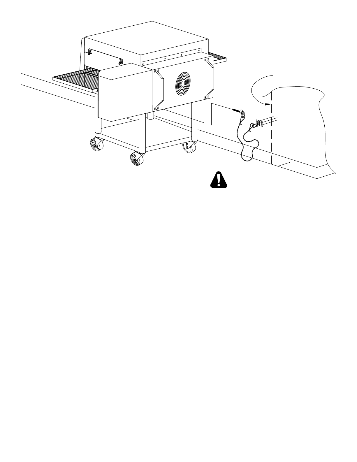
ACCESS CONSIDERATIONS
Locating the gas valve(s), quick connect hose(s) and electrical outlet(s) at the control box end of the
oven will allow easier access for any service visits. This improved access should make any necessary
service quicker resulting in less kitchen disruption. It will also allow easier disconnection of electricity,
gas, and restraints for cleaning around and behind the oven.
ELECTRICAL CONNECTION
Before making any electrical connections to this unit, check that the power supply is adequate for the
voltage, amperage, and phase requirements stated on the rating plate. A wiring diagram is included
herewith.
When installed, this appliance must be electrically grounded and its installation must comply with the
National Electric Code, ANSI-NFPA 70, latest version, manufacturer's installation instructions, and
applicable local municipal building codes. In Canada, all electrical connections are to be in accordance
with CSA C22.1 - Canadian Electrical Code Part 1 and/or local codes. Other international installations
will need to comply with IEC codes, manufacturer's installation instructions, and applicable local
municipal building codes.
PRESSURE REGULATION AND TESTING
Each oven has been adjusted at the factory to operate with natural gas. Parts can be ordered
for conversion for use with propane.
Each oven is supplied with a regulator to maintain the proper gas pressure. The regulator is
essential to the proper operation of the oven and should not be removed. A pressure reading can be
taken at one of the 1/8" NPT test ports on the bottom or side of the combination valve. The reading
should be taken while the oven is heating up. The regulator is located on the bottom of the gas
combination valve, just inside the control box. There is no need to install an additional regulator
where the oven connects to the gas supply unless the supply exceeds the maximum.
NOTE: The supplied regulator is evaluated for a maximum gas supply pressure of
14" water column (34.5 mBar). The recommended maximum gas supply pressure
is 12" water column (29.9 mBar).
Installation must conform with local codes or, in the absence of local codes, with the National Fuel
Gas Code, NFPA54/ANSI Z223.1 - Latest Edition, the Natural Gas Installation Code CAN/CGA-
B149.1 or the Propane Installation Code CAN/CGA-B149.2 as applicable.
During pressure testing note the following:
1. The oven and its individual manual shut-off valve must be disconnected from the gas supply piping
system during any pressure testing of that system at test pressures in excess of 1/2 psig (3.45 kPa).
Turn OFF main gas shut-off valve or main gas supply line.
2. The oven must be isolated from the gas supply piping system by closing its individual manual shut-
off valve during any pressure testing of the gas supply piping system at test pressures equal to or
less than 1/2 psig (3.45 kPa).
3. If incoming pressure is over 14" water column, a separate regulator for the oven must be installed
before the gas supply to the oven. For LP it must regulate pressure to 11" water column (27.1 mBar)
maximum and 6" for NAT.
8
CAUTION

WARNING: To prevent damage to the control valve regulator during the initial
turn-on of gas, it is very important to open the manual shut-off valve very slowly.
After the initial gas turn-on, the manual shut-off valve must remain open except
during pressure testing as outlined in the above steps or when necessary during
service maintenance.
9
STACKING INSTRUCTIONS
The following instructions should be followed when
stacking more than one unit.
Single Oven (or Bottom) Cart Install:
1. Remove door, conveyor, and nger assemblies.
2. Unbolt unit from shipping crate (2 bolts).
3. Turn unit on front as shown.
4. Slide legs into stand shelf and thread legs into
bottom of oven.
5. Install casters into bottom of legs. Place casters
with brakes to the front.
6. Position shelf as desired and fasten to legs.
7. CAREFULLY lift oven upright.
Stacked Oven Install Preparation:
1. Remove door, conveyor, and nger assemblies.
2. Unbolt unit from shipping crate (4 bolts).
3. Turn unit on front as shown.
4. Remove top of lower oven (4 screws total, 2 each
front and rear) and bolt to stacked oven base using
5/8 - 11 bolts (4 each, included).
5. Place top oven on lower unit and re-attach with
screws for top of lower oven.
6. Use restraint on lowest oven to prevent any high
loads that could tip the oven stack.

RESTRAINT REQUIREMENT
1. The installation shall be madewith a gasconnector that
complies with local codes for connectors for movable
gas appliances and a quick-disconnect device that
complies with local codes for such devices in use
with gas fuel.
2. The installation of the restraintmust limit themovement
of the oven(s) without depending on the connector,
the quick disconnect device, or associated piping to
limit the oven movement.
3. If the restraint must be disconnected during
maintenance or cleaning, it must be reconnected after
the oven has been returned to its originally installed
position.
OPERATING INSTRUCTIONS
DO NOT ATTEMPT TO OPERATE THE OVEN until
connection of utility service and installation has been fully
inspected (start-up check-out) by an authorized service
technician or a Star Service Technician in order to assure
the oven is properly installed and in working order. The
warranty becomes effective upon verication of
proper installation.
CAUTION
DO NOT WORK AROUND THE CONVEYOR
BELT WITH LONG HAIR, LOOSE CLOTHING,
OR DANGLING JEWELRY. GETTING
CAUGHT IN THE BELT COULD RESULT IN
DISMEMBERMENT OR FATAL INJURY.
Unless specied otherwise, conveyor travel is factory
set for left to right operation when facing the front of the
oven. If a direction change is required, refer to "DISPLAY
INFORMATION," section 3 for instructions on how to
program the controller for a direction change. In addition,
the conveyor belt must be changed to travel in the new
direction.
SAFETY OPERATING INSTRUCTIONS
The information contained in this section is provided
for the use of qualied operating personnel. Qualied
operating personnel are those who have carefully read
the information contained in this manual, are familiar
with the functions of the oven and/or have had previous
experience with the operation of the equipment described.
Adherence to the procedures recommended herein will
assure the achievement of optimum performance and
long, trouble-free service.
10
HOLLOW WALL STUD
OR MASONRY WALL
A
B
C

Please take time to read the following safety operating instructions. They are the key to the
successful operation of your Ultra-Max Conveyor Oven.
SAFETY TIPS
For your safety, read before operating.
If you smell gas:
1. DO NOT try to light any appliance.
2. DO NOT touch any electrical switches.
3. Use anexterior phonetocall yourgas supplier
immediately.
4. If you cannot reach your gas supplier, call
the re department.
In the event of a power failure:
1. Turn all switches off.
2. DO NOT attempt to operate the oven until
the power is restored.
11
IL3046
®
SELECTING COOK OPTIONS:
1. PRESS & HOLD FOR 1/2 SECOND.
2. PRESS REPEATEDLY TO CHOOSE YOUR COOKING OPTION.
3. PRESS TO ACCEPT OR WAIT AND SETTINGS WILL RESET.
Consult the manual for instructions to change option settings.
Consultez le manuel pour les instructions pour modifier les parametres d’ options.
’
Comment selectionner des options:
1. Appuyez maintenez pendant 1/2 seconde.
2. Appuyez sur a plusieurs reprises pour les options.
3. Appuyez sur pour accepter ou attendre rearmement automatique.
’
’
’
General Safety Tips:
1. If the oven needs to be moved for any reason,
the power must be disconnected from the unit
before doing so.
2. DO NOT remove the control box cover unless
the oven is unplugged.
OPERATION
To turn the oven on:
1. Push the power switch to "ON."
2. After the fan begins to buildpressure, the pressure
switch will provide power to the control board
to engage the heating element contactor. You
should hear an initial "click" from the contactor
as it begins to heat.
To adjust the time and temperature:
1. Press the DOWN and UP arrows
( ) at the same time. Hold for four seconds
until the TIME display goes blank.
2. Press the ENTER button ( ) to switch between
TIME and TEMPERATURE.
3. Press the UP arrow ( ) to increase or the
DOWN arrow ( ) to decrease the TIME or
TEMPERATURE. Hold either button down for
faster display changes.
4. After ve seconds, the new numbers will be saved
and the oven will display the new settings.
SELECTING COOKING OPTIONS
1. Press & hold for 1/2 second.
2. Press repeatedly to choose your cooking
option.
3. Press to accept or wait and setting will reset.
To turn the oven off:
1. Push the power switch to "OFF." The oven is
equipped with a cool-down feature for motor shaft
and bearing protection. This enables the blower
motor(s) to run regardless of the controller status.
The blower(s) continue to run until the oven cools
to a safe temperature.
COOKING OPTION
OPTION TEMP TIME
1 500°F/260°C 8:00
2 400°F/204°C 14:00
3 450°F/232°C 16:00
4 500°F/260°C 10:00
5 450°F/232°C 12:00
6 400°F/204°C 20:00

12
DISPLAY INFORMATION
When operating the oven, there are different
levels of access:
1. Store Level - General employees would know
these functions and how to change them. While
the oven is running, enter this mode by holding the
DOWN and UP arrows ( ) simultaneously for
four seconds. The TIME display goes blank and the
TEMP setpoint is displayed. Adjust with the DOWN
or UP arrows. The ENTER button ( ) toggles
between TIME and TEMP. The parameter that can
be adjusted is displayed, the other is blank. When
TIME and TEMP are adjusted as needed, wait ve
seconds and SAVE is displayed. The values are
accepted and thecontroller begins controlling tothese
new values. The conveyor continues to operate at
the same speed until a new value is accepted. The
temperature control output should be OFF during
changes.
2. Manager Level - This is a lock so that TIME and
TEMP cannot be changed even at the Store Level.
While the oven is running, enter this mode by holding
the DOWN and UP arrows simultaneously for 4
seconds. TheTIME displaygoesblankand theTEMP
setpoint is displayed. Release the UP arrow and
continue to hold the DOWN arrow for an additional
4 seconds. The TEMP display shows LOC as the
TIME display shows nO, which indicates that the
TIME/TEMP parameters can be changed. after
reaching the STORE level. yES indicates that the
parameters cannot be changed even after entering
the STORE level. The LOC setting can be toggled
using the ENTER button ( ).
ADDITIONAL FUNCTIONS
The conveyor belt direction and the temperature display can
be changed on the conveyor oven by a qualied technician.
To change the belt direction, the technician must reverse the
motor direction and rotate the conveyor belt for proper oven
function. Atechnician can also change the temperature display
from Fahrenheit to Celsius. These changes can be made by
the technician during the start-up/check-out or at a later date.
ERROR CODES
Error codes will display as ashing text messages for diagnostic
purposes. Any temperature or thermocouple error should turn
the temperature output OFF and leave the conveyor running
at the same speed. The belt error should turn the temperature
output OFF. The speed error should display when the motor is
unable to settle at the chosen speed. This might occur if a fast
speed is chosen that the motor is unable to spin fast enough
to achieve. The speed signal output will remain the same but
the display will ash the error message.

BAKE TIME VERSUS TEMPERATURE
1. Bake time is actually conveyor speed and is dened
as the time the product is actually in the oven. This is
measured by noting the time when the leading edge of
the product enters the oven and the time the leading
edge of the product leaves the oven. This is adjusted
by using the conveyor speed controller.
2. Bake temperature is adjusted by changing the setpoint
of the temperature controller to the desired bake
temperature. When the oven reaches the desired
temperature, the red dot in the lower right corner of the
temperature display will turn off and on as the controller
maintains the temperature.
3. When establishing a bake time and temperature for a
given product, the general rule shall be as the bake
time increases the bake temperature decreases and the
reverse isalso true; increasetemperature, decrease time.
However, there are limits to the above rule. Going to
extremes will result in a burntexterior and raw interior or it
will result in a very light color but over-baked product.
4. Once a good bake has been established, the ne
adjustments should be made by holding either the bake
time or bake temperature constant, then varying the
other.
CONVEYOR SPEED
Bake Time (Conveyor Speed) - As stated previously, bake
time (conveyor speed) is dened as the amount of time
elapsed between the time the leading edge of the product
enters the oven and the leading edge of the product exits
the oven. Bake time is controlled by adjusting the digital
speed controller. The setting on the control panel indicates
the actual bake time.
Bake time will be the same for any size product.
TIME OF DELIVERY
The time of delivery is the amount of elapsed time between
the period when the leading edge of the product enters the
oven and the trailing edge of the product is fully discharged
and is ready to be delivered to the customer.
Time of delivery changes if the product size changes.
Tip: Train yourself not to pull the product out of the oven
when the leading edge comes out. Always wait until the entire
product is out - the product needs this time to fully bake.
13
BAKE vs. DELIVERY TIME
Time to Delivery changes with product
but
Bake Time remains constant
at a steady conveyor speed.
28 (BAKE)
36 (DELIVERY)
44 (DELIVERY)
6:00 (BAKE)
7:43 (DELIVERY)
9:26 (DELIVERY)

MAINTENANCE INSTRUCTIONS
DISCONNECT THE POWER SUPPLY BEFORE SERVICING OR CLEANING THIS
OVEN. SAFEGUARD THE POWER SO ITCANNOT BEACCIDENTALLYRESTORED.
FAILURE TO DO SO COULD RESULT IN DISMEMBERMENT, ELECTROCUTION,
OR FATAL INJURY. THERE IS MORE THAN ONE POWER SUPPLY CONNECTION
POINT WHEN OVENSARE STACKED, SO MAKE SURE THATALL SWITCHESARE
IN THE OFF POSITION BEFORE CLEANING OR MAINTENANCE.
No electrical components should be subjected to moisture. It is therefore important that the oven is wiped
down carefully. NEVER throw buckets of water over the oven or subject it to pressure washing from a
hose or a pressure spray. If water or other liquid is spilled on the oven, make sure that none of it has
entered the control box area before switching the oven ON. If in doubt, call your service company.
Adhere to the following warnings when cleaning or maintaining your gas conveyor oven:
1. The oven must be cool. Do not use power cleaning equipment, steel wool, or wire brushes on
stainless steel surfaces.
2. Do not use a caustic or an alkaline base cleaner on the interior of the oven. This will ruin the
aluminized nish of the oven interior.
3. When using cleaning solutions, be sure they meet local and national health standards.
If the gas oven needs to be moved, the gas must be turned off and disconnected
from the unit before moving the restraint. Reconnect the restraint after the oven
has been returned to its original location.
Follow this recommended cleaning schedule for proper oven performance:
DAILY
1. Clean the conveyor belt using a nylon brush. Allow any foreign material to drop into the crumb
pans.
2. Empty and clean the crumb pans. Use a hot water and detergent mix.
Rinse with clean water.
EVERY MONTH
1. Brush and clean the guard on the motor cooling fan.
EVERY THREE MONTHS
1. Unplug the oven and disconnect gas connections.
2. Remove the crumb pans.
3. Remove the conveyor assembly.
4. Unlatch and remove the front door. Remove all internal airow components.
5. Clean the oven interior with an appropriate oven cleaner.
6. Clean the conveyor assembly, crumb pans, and other removable components. Wash in a hot water,
detergent mix and rinse with clean water. For difcult cleaning areas, use a heavy-duty de-greaser
or oven cleaner.
7. Move the oven and clean under it. Be careful not to damage the oven's gas hose or electrical cords
when moving.
8. Reassemble the oven.
EVERY TWELVE MONTHS
A factory authorized service person should:
1. Open and clean the inside of the control box.
2. Check and tighten all electrical components.
If maintenance is required, contact your local service company, a factory representative,
or Star Manufacturing.
14
WARNING
CAUTION
CAUTION

1. Remove crumb trays and
shelves from both ends.
DIRECTIONS FOR DISASSEMBLY
2. Push the spring-loaded coupling
in to disengage the pin in the
shaft. Rotate the shaft so the pin
will not go back in the coupling
slots.
4. Finish removing the conveyor
assembly from the right end of
the oven.
3. Lift uptheleftendoftheconveyor
frame so thecrumb tray supports
clear the tunnel opening. Push
the conveyor frame through the
tunnel opening.
5. Upper nger assembly can be
removed complete or the small
handle (left) can be used to slide
nozzle and columnating plate
out before removing the main
body.
7. The lower nger assembly can
be removed complete or the
nozzle can be slid off to reveal
the recessed columnating
plate.
6. Upper nozzle (with slot) and
columnating plates (with tab).
Extruded holes all point in the
same direction (down toward
the conveyor).
8. The columnating plate also has
a slot that must align with a tab
on the nger to ensure proper
orientation. Extruded holes
point up toward the bottom of
the conveyor.
9. The oven body is now ready to
be wiped clean. Reassemble
the nger and conveyor parts
in the reverse order after
cleaning.
15

CONVEYOR BELT TENSION
The conveyor belt of the Ultra-Max Gas Conveyor Oven
does not have a tension adjustment. If the belt becomes
too loose, a link will have to be removed to tighten. A
belt that is too tight will also cause operational problems
due to excessive drag. We suggest that you have a
qualied service technician perform this adjustment.
CAUTION
Careful consideration should be exercisedprior
to removing a belt link because a belt that is
too tight will impede the smooth operation of
the conveyor.
CONVEYOR BELT LINK REMOVAL
An entire link can be removed with the conveyor assembly
either in or out of the oven. This may be necessary as the belt
stretches after continuous use. Following are the necessary
steps for removing links:
1. Move the splice clips to either end of the oven for easy
access.
2. Unhook the splice clips using long nose pliers.
3. Unhook the full link to be removed and slide it out.
Do not discard the link removed as it may be used for
making spare splice clips.
4. Reconnect the inside splice clips.
5. Reconnect the outside splice clips.
6. Replace all parts removed from the oven.
7. Straighten any bent wires to ensure smooth sprocket
engagement.
16
Remove the outside master links on the right and left
sides of the conveyor belt. Remove the center splice
clips next.
Unhook the end loop and pull up on the link section.
Save this link as it may be used for making splice
clips.
Check the orientation of the splice clips (the hooks
should be up). The belt shown is the top section,
ready for left-to-right travel.

MOV
3423
33
25
2 8
30 15
8A
15A
GND GND
1
42A
43A
44A
15A
8A
32
29
42
28
45A
29
27
28
12
X
32
10K OHM
RESISTOR
32
45A
28
42
29
35

8 TH(l2PPR)
L _____________
I 7
I
O
£
3: FG
sv
�o
�
z
O
n
,
er
0
I
0
I
z
I
�
0
�o
�
J�
�
5 .
z
e>
'
z
c�
r
z
a
z
0
<
z
0

1678 2345
1
8
10
29
38
26
23
22
25
27
21
24
39
13
20
17
18
16
15
14 3
4
6
9
5
7
11
12
19
31 32
2
34
33
35
36
37
MODEL UM1854
CONTROL BOX ASSEMBLY
SOME ITEMS ARE INCLUDED FOR ILLUSTRATIVE
PURPOSES ONLY AND IN CERTAIN
INSTANCES MAY NOT BE AVAILABLE.
THIS DRAWING CONTAINS INFORMATION CONFIDENTIAL
TO STAR MANUFACTURING INTERNATIONAL, INC.
NO REPRODUCTION OR DISCLOSURE OF ITS CONTENTS IS PERMITTED.

PARTS LIST August 25, 2011, Rev. M
Ultra-Max Gas Conveyor Oven
UM1854-NAT/LP CONTROL BOX
Description
1 G9-GC0013 1 CONTROL BOX DOOR
2PS-Z7718 1 TIME & TEMP CONTROLLER GAS OVEN 120V
3G9-Z5250 1 POWER SUPPLY BRACKET
G9-Z5251 OBSOLETE GEARMOTOR BRACKET
GEARMOTOR MOUNT BRACKET (FROM 07/27/10)
4G9-Z13295 1
5G9-Z5249 1 CONTROL BOX LID
62T-Z5175 1 THERMOSTAT, COOL DOWN, 120°F
72T-Z5176 1 THERMOSTAT, HI-LIMIT, 140°F
82T-Z5177 1 HIGH TEMPERATURE LIMIT
92E-Z5206 1 10AMP CIRCUIT BREAKER
10 2E-Z5683 1 VACUUM SWITCH
11 2E-Z1858 1 LIGHTED SWITCH
12 2E-Z5663 2 POWER RESISTOR BRACKETS
2E-Z6607 1 POWER RESISTOR - 5 OHM
13 2J-Z5189 1 THERMOCOUPLE/TEMP PROBE
14 G9-Z6611 1 POWER SUPPLY - 24VDC (115V INPUT) MANUFACTURED BEFORE OCT. 2010
15 2E-Z5162 1 TRANSFORMER
16 PS-Z11800 1 KIT, IGNITION CONTROLLER (OBSOLETE)
16 PS-Z11801 1 KIT, IGNITION CONTROLLER (CE & UK) (OBSOLETE)
17 G9-Z5661 1 ELECTRODE SET
G9-EC0135 GEARMOTOR mfg from 04/18
18 2U-Z10407 GEARMOTOR 40:1 UM1854Q-NATX, UM1854Q-LPX
2U-Z5171 1GEARMOTOR 500:1 24V DC, mfg before Oct 2010 UM1854-LP, UM1854-NAT
2U-Z13292 GEARMOTOR 240:1 120VAC, mfg after Sept 2010 UM1854-LP, UM1854-NAT
2U-Z13498 GEARMOTOR 40:1 120V UM1854Q-LP, UM1854Q-NAT
19 2A-Z6534 1 COUPLING
2F-Z5173 BURNER - NATURAL
2F-Z5660 BURNER - PROPANE
G9-Z5670
G9-Z5671 1#33 ORIFICE (HI NATURAL)
#56 ORIFICE (LO NATURAL) (INCLUDED IN BURNER)
20 G9-Z5672 #50 ORIFICE (HI LP)
G9-Z5673 #66 ORIFICE (LO LP) (INCLUDED IN PROPANE BURNER)
HIGH ALTITUDE LP
2A-Y1255 1#52 ORIFICE (HI LP) HIGH ALTITUDE
2J-Z13829 #68 ORIFICE (LO LP) HIGH ALTITUDE
21 2K-2667 1 PIPE ELBOW
22 2K-Z3381 1 PIPE NIPPLE
23 2K-Z5105 1 COMPRESSION ELBOW
24 2K-Z5106 1 COMPRESSION ELBOW
25 2V-Z5103 1 GAS COMBINATION VALVE - NATURAL - 24VAC
2V-Z5659 KIT PROPANE REGULATOR KIT
26 2V-Z5104 1 GAS SOLENOID VALVE - 24VAC
27 G9-GC0001 1 BULKHEAD FITTING
28 2V-Z5194 2 STAINLESS FLEX TUBE
29 2C-Z5195 1 CONDUIT HANGER
30 2E-Z5187 1 WIRING KIT (COMPLETE)
31 2K-Z1971 4 SPACER (.188)
32 2C-Z5427 4 SPACER (.120)
33 2C-Z0216 2 SCREW M4 (METRIC)
34 2E-Z4597 2 TERMINAL BLOCK
35 2C-Y2344 1 GROUND TERMINAL
36 2K-Y2968 1 BUSHING, CORD STRAIN RELIEF
37 2E-Z5172 1 CORD SET
38 2E-Z5181 1 CAPACITOR - FAN MOTOR
39 2V-Z5194 2 SS FLEX 3/8 X 1/2
NI 2E-Z5187 1 WIRING HARNESS, GEARMOTOR
NI 2M-Z5568 1GRAPHIC, FRONT UM1854
NI 2W-Z5668 1 CANDLE, WHITE SMOKE, CONVY. OVEN START UP
NI 2E-Z22343 1 SPEED CONTROL
This manual suits for next models
4
Table of contents
Other Ultra Max Oven manuals