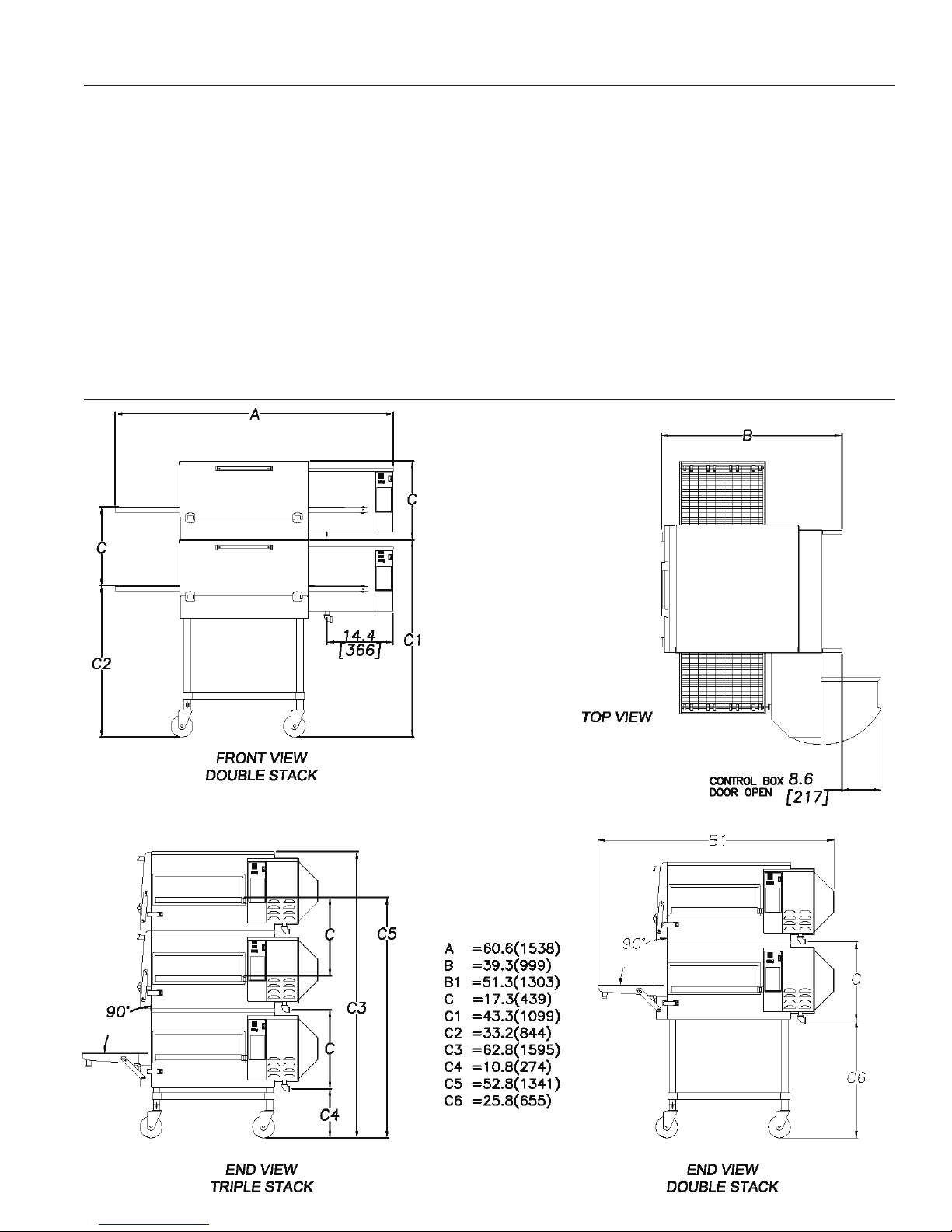
The following drawing shows a typical installation
and is intended to be a guideline. This is not a rigid
specication. Hood dimensions and positioning over
the oven will vary with hood manufacturer.
SMOKE CANDLE TEST
Inordertoverifytheproperfunctionofyourventilation
system,asmokecandletestshouldbedone. Iftesting
a multiple oven system, this test should be done on
the bottom oven. The conveyor coupling should be
disconnected and the oven temperature must be set
and operating at a minimum of 480°F (249°C).
Test Procedure:
1. Wear heat-resistant gloves to prevent burns.
2. Put the smoke candle in an 8"x8"x2" cake pan.
3. Insert candle through conveyor tunnel or oven
door. (Use Star Smoke Candle 2W-Z5668.)
4. Lightthefuseofthesmokecandleandimmediately
center the pan in the oven cavity on the conveyor
belt (keeping the oven door closed).
5. Observethesmokepatterncomingoutofalloven
openings and the collection of this smoke by the
ventilation system.
6. All smoke from the oven must be captured by the
ventilation system.
GAS SUPPLY RATING AND SIZING
Calculations for pipe sizing must take into account
themaximumusagerateofallotherappliancesinthe
kitchenoroneormoreoftheapplianceswillsufferfrom
inadequateordangerousperformance. The1/2"NPT
connection for the oven is generously sized for use
in the control box of the oven. However, unless the
oven installation is within 10 feet of the main building
gassupply,thesupplymustbelarger. Foreachoven,
a 3/4" NPT exible quick connect hose and full port
gas shut-off valve is recommended as a MINIMUM.
Themainpipesupplyingeachovenbranchmayneed
to be larger depending on the number of appliances
serviced, the number of elbows in the piping, and
the pressure. This should be sized and installed by
a professional familiar with any local codes that may
also affect the installation.
ACCESS CONSIDERATIONS
Locating the gas valve(s), quick connect hose(s) and
electrical outlet(s) at the control box end of the oven
will allow easier access for any service visits. This
improvedaccessshouldmakeanynecessaryservice
quickerresulting inless kitchendisruption. Itwillalso
allow easier disconnection of electricity, gas, and
restraints for cleaning around and behind the oven.
ELECTRICAL CONNECTION
Before making any electrical connections to this unit,
checkthatthepowersupplyisadequateforthevoltage,
amperage, and phase requirements stated on the
rating plate. A wiring diagram is included herewith.
When installed, this appliance must be electrically
grounded and its installation must comply withANSI-
NFPA 70, latest version, manufacturer's installation
instructions, and applicable local municipal building
codes. InCanada,allelectricalconnectionsaretobe
in accordance with CSAC22.1 - Canadian Electrical
Code Part 1 and/or local codes.
PRESSURE REGULATION AND TESTING
Eachovenhasbeenadjustedatthefactorytooperate
withnaturalgas. Partscanbeorderedforconversion
for use with propane.
Each oven is supplied with a regulator to maintain
the proper gas pressure. The regulator is essential
to the proper operation of the oven and should not be
removed. Apressure reading can be taken at one of
the 1/8" NPT test ports on the bottom or side of the
combinationvalve. Thereadingshouldbetakenwhile
theovenisheatingup. Theregulatorislocatedonthe
bottom of the gas combination valve, just inside the
control box. There is no need to install an additional
regulator where the oven connects to the gas supply
unless the supply exceeds the maximum.
NOTE: The supplied regulator is evaluated for a
maximum gas supply pressure of 14" water column
(34.5mBar).Therecommendedmaximumgassupply
pressure is 12" water column (29.9 mBar).
Installation must conform with local codes or, in the
absence of local codes, with NFPA54/ANSI Z223.1
- Latest Edition, the Natural Gas Installation Code
CAN/CGA-B149.1 or the Propane Installation Code
CAN/CGA-B149.2 as applicable.
7