Ultrasonic P500 Manual

www.ULTRASONICPOULTRYSYSTEMS.com
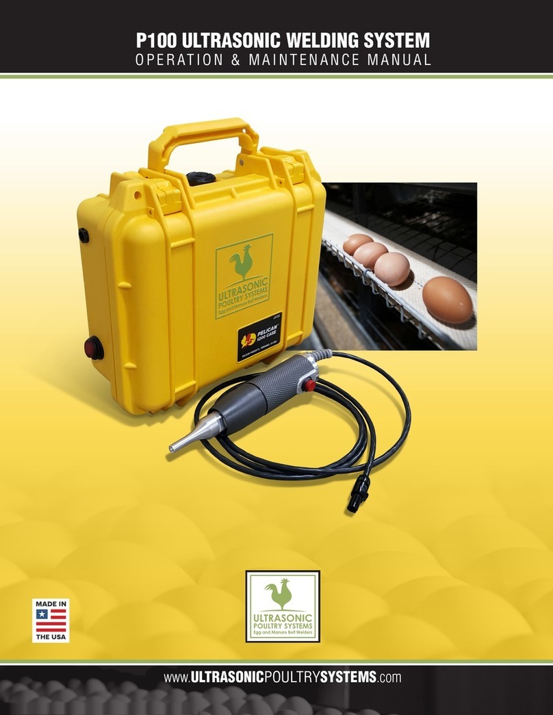
P500 ULTRASONIC WELDING SYSTEM
OPERATION & MAINTENANCE MANUAL
WATCH THE VIDEO:
ultrasonicpoultrysystems.com

ATTENTION: This manual and the engineering
information it contains, is proprietary and is
provided to our customers for the sole purpose of
operating and maintaining the Ultrasonic Poultry
Systems equipment it describes. This is not to be
given or made available to anyone who might use
this information to the detriment of any entity of
Ultrasonic Poultry Systems.
TABLE OF CONTENTS
Table of Contents..............................................................2
Introduction.........................................................................2
Overview of Ultrasonic Assembly...............................2
What is Ultrasonics?
Principle of Ultrasonic Assembly
Ultrasonic Hand-held Welders
Welder Specifications .....................................................3
Components and Use......................................................3
Important Safeguards .....................................................4
Installation ...........................................................................4
Inspection
Electrical Requirements
Safety
Preperation for Use
Quick Start Instructions..................................................5
Getting Started/How to Use
Troubleshooting
Component/Accessory Illustrations...........................6
Warranty Information......................................................7
Return Information ...........................................................7
INTRODUCTION
The model P500 is a portable 40 kHz, 500 watt,
hand held ultrasonic welder used for plastics
assembly. It consists of an ultrasonic power
supply and a hand gun. These units are
designed specifically for welding, staking,
and spot welding applications.
OVERVIEW OF ULTRASONIC
WELDING SYSTEM
What is Ultrasonics?
Ultrasonics refers to vibrational waves with a
frequency above the human audible range which
is usually above 18,000 cycles per second (Hz).
Ultrasonic Welding
The basic principle of ultrasonic assembly involves
conversion of high frequency electrical energy to
high frequency mechanical energy in the form of
reciprocating vertical motion which, when applied
to a thermoplastic, generates frictional heat at the
plastic/plastic interface. In ultrasonic welding, this
frictional heat melts the plastic, allowing the two
surfaces to fuse together; in ultrasonic staking or
insertion, the controlled flow of molten plastic is
used to capture or lock another material in place.
Ultrasonic Hand-held Welders
Ultrasonic hand-held welders are generally
composed of the following major elements: a
power supply, hand gun (converter), and horn as
detailed in the diagram on the next page. A review
of this diagram will help you understand the basic
elements involved in the assembly process and
their relation to each other.
2

WELDER SPECIFICATIONS
Power Requirements:
110-240 VAC
Output Frequency:
40 kHz
Amplitude Range:
Adjustable by horn design
Dimensions:
H13.50" x W17.00" x D9.00"
Power Supply Weight:
13 lb (5.90 kg)
Compact Hand Piece Weight:
1 lb (.45 kg)
Cable Length:
10' (3.05 m)
COMPONENTS AND USE
Lever:
Start Switch (Activates the Ultrasonics).
Tip Installation:
Clean the mating surfaces. Make sure the M8 x 1.25 mm
stud is tight in the horn (30-35 in/lb). Always use open
end wrenches on the wrench flats! Make sure the horn is
tight to the driver (converter).
3

IMPORTANT SAFEGUARDS
Read before installing or using the equipment
Your Ultrasonic Welding System has been de-
signed with safety in mind. However, no design
can completely protect against improper usage,
which may result in bodily injury and/or property
damage. For your protection and equipment safe-
guard, observe the following warnings at all times,
read the operating instructions carefully before
operating the equipment, and retain this instruc-
tion manual for future reference. If the Ultrasonic
Welding System is used in a manner contrary
to that specified in this instruction manual, the
protection features designed into the unit may be
impaired.
• High voltage is present in the power supply.
Do not remove the cover. Refer all servicing to
qualified service personnel.
• Never operate the power supply unless it is
connected to the hand gun (converter).
• Never secure anything to the tip.
INSTALLATION
Inspection
Prior to installing the Ultrasonic Welding System,
perform a visual inspection to detect any evidence
of damage, which might have occurred during
shipment. Before disposing of any packaging
material, check it carefully for small items.
The Ultrasonic Processor was carefully packed and
thoroughly inspected before leaving our factory.
The carrier, upon acceptance of the shipment,
assumed responsibility for its safe delivery. Claims
for loss or damage sustained in transit must be
submitted to the carrier.
If damage has occurred, contact your carrier
within 48 hours of the delivery date. DO NOT
OPERATE DAMAGED EQUIPMENT. Retain all
packing materials for future shipment.
Electrical Requirements
The Ultrasonic Processor requires a fused, single
phrase electrical outlet capable of supplying
60 Hz at 110 volts or optional 220 volts. Contact
Ultrasonic Poultry Systems for the right plug for
your region.
Safety
Operating the equipment with voltages dierent
from those specified, or with voltages with high
power transients, will cause components within
the power supply to fail.
Preparation for Use
1. Plug the electrical line cord into the electrical
outlet, MUST HAVE A GROUND CONECTION.
if the unit is already on; depress the key.
2. If the converter / horn assembly is not already
assembled; screw the horn onto the converter
and secure with wrenches provided.
3. Connect the converter cable to the
power supply.
4.The following pages show standard horns.
4

5
QUICK START INSTRUCTIONS
Getting Started/How to Use
1. Place the tip onto the belt to be welded and
apply pressure
2. Still applying pressure, press the start switch
and hold pressure for 1-2 seconds
3. Release the switch and apply higher pressure
– hold for 1-2 seconds to allow weld to cool
Troubleshooting
A. System is not welding
i. Verify system is plugged in (110-240VAC)
with ground
ii. Verify power switch is on – is light illuminated?
iii. Is tip fully tightened? Use two wrenches
iv. Pressing too hard
v. Check tip – is tip worn?
You can touch the side of the tip
vi. System goes into overload when triggering
handpiece: Check to see that handpiece is not
making any ground contact
This is a safety feature so that operator
does not get an electrical shock
B. Tip is hot
C. Technical Support: 614.549.0627
1. Place the tip onto the belt to be welded and
APPLY LIGHT PRESSURE
2.Still applying light pressure, press the start switch
and HOLD LIGHT PRESSURE for 1-2 seconds
3.Release the switch and APPLY HIGHER PRESSURE
– hold for 1-2 seconds to allow weld to cool

P100
8
FEATHER GLIDE EGG BELT –1.3mm
MANURE BELT –1mm (Shown Above)
Other Tips Are Available For Different
Thickness Materials
PERFORATED EGG BELT –1.3mm
E20
M30
M20
P100
8
FEATHER GLIDE EGG BELT –1.3mm
MANURE BELT –1mm (Shown Above)
Other Tips Are Available For Different
Thickness Materials
PERFORATED EGG BELT –1.3mm
E20
M30
M20
P100
8
FEATHER GLIDE EGG BELT –1.3mm
MANURE BELT –1mm (Shown Above)
Other Tips Are Available For Different
Thickness Materials
PERFORATED EGG BELT –1.3mm
E20
M30
M20
P100
8
FEATHER GLIDE EGG BELT –1.3mm
MANURE BELT –1mm (Shown Above)
Other Tips Are Available For Different
Thickness Materials
PERFORATED EGG BELT –1.3mm
E20
M30
M20
P100
8
FEATHER GLIDE EGG BELT –1.3mm
MANURE BELT –1mm (Shown Above)
Other Tips Are Available For Different
Thickness Materials
PERFORATED EGG BELT –1.3mm
E20
M30
M20
P100
8
FEATHER GLIDE EGG BELT –1.3mm
MANURE BELT –1mm (Shown Above)
Other Tips Are Available For Different
Thickness Materials
PERFORATED EGG BELT –1.3mm
E20
M30
M20
E20-5 Feather Glide Egg Belt – 1.3 mm
M20-5 Manure Belt – 1.0 mm (shown above)
Other tips are available for dierent thickness materials
M30-5 Perforated Egg Belt – 1.3 – 1.7 mm
P100
8
FEATHER GLIDE EGG BELT –1.3mm
MANURE BELT –1mm (Shown Above)
Other Tips Are Available For Different
Thickness Materials
PERFORATED EGG BELT –1.3mm
E20
M30
M20
P100
8
FEATHER GLIDE EGG BELT –1.3mm
MANURE BELT –1mm (Shown Above)
Other Tips Are Available For Different
Thickness Materials
PERFORATED EGG BELT –1.3mm
E20
M30
M20
P100
8
FEATHER GLIDE EGG BELT –1.3mm
MANURE BELT –1mm (Shown Above)
Other Tips Are Available For Different
Thickness Materials
PERFORATED EGG BELT –1.3mm
E20
M30
M20
ACCESSORIES (included)
Two wrenches (9/16, 11/16)
Three standard 40 kHz horns
6

7
WARRANTY GUARANTEE
Ultrasonic Poultry Systems warrants its products
for a period of one year from the date of shipment
against any defect in material or workmanship
under normal installation, use, and maintenance as
described in the operating instructions. Labor is
provided under warranty for a period of six months
from date of purchase.
During the warranty period, Ultrasonic Poultry
Systems will, at its option, either repair or replace
without charge for material and labor, the part(s)
which prove upon our examination to be defective,
provided the defective unit is returned to us properly
packed with all transportation charges prepaid. If
the purchaser desires Ultrasonic Poultry Systems
personnel to come to their facility for warranty work
and/or production debugging, the purchaser will be
billed on a time and expense basis. Any alteration
or modification of the machine by the customer
without prior written approval by Ultrasonic Poultry
Systems will void all warranties. Ultrasonic Poultry
Systems will not exceed the manufacturers warranty
on any purchased components.
All tooling and ultrasonic horns are warranted for a
period of one year. Ultrasonic Poultry Systems will
repair or replace cracked or defective horns and
tooling once without charge, if the failure occurs
during the warranty period.
NOTE: The warranty will not cover normal
and expected wear on tooling and horns. Any
equipment judged by Ultrasonic Poultry Systems
personnel to have been worn out by normal use, will
not be replaced under the warranty conditions.
Ultrasonic Poultry Systems reserves the right not
to warrant horns of unusual or experimental design
which in our judgment are likely to fail during use.
Ultrasonic Poultry Systems equipment is
designed for maximum operator safety and
includes built-in safety devices. Any modification
of these devices will void the warranty. Ultrasonic
Poultry Systems assumes no responsibility for
damages or injuries resulting from the
modification of said safety devices.
The warranty does not apply to equipment which
has been subjected to unauthorized repair, misuse,
abuse, negligence, or accident. Equipment that, in
our judgment, shows evidence of such damage will
be ineligible for service under this warranty.
Under no circumstances shall Ultrasonic Poultry
Systems be liable to the purchaser or to any
other person for any incidental or consequential
damages or loss of profit or product resulting
from any malfunction or failure of this Ultrasonic
Poultry Systems product. Due to the wide range
of machinery and equipment provided by and
produced by Ultrasonic Poultry Systems, there are
a few exceptions to this warranty. These exceptions
will be handled on a case-by-case basis, based
on the merit of the exception and the conditions
of the operation of the machinery in question. To
arrange for an exception to the warranty, present all
information in writing to Ultrasonic Poultry Systems
and it will be taken into consideration.
RETURN INFORMATION
An RMA number is required to return equipment
to Ultrasonic Poultry Systems.
Contact Ultrasonic Poultry Systems at:
Ultrasonic Poultry Systems
6160 Seeds Road, Grove City, OH 43123
614.549.0627 or 614.539.3207
www.UltrasonicPoultrySystems.com


www.ULTRASONICPOULTRYSYSTEMS.com
SISTEMAS ULTRASÓNICOS DE SOLDADURA DE CINTAS
MANUAL DE OPERACIÓN & MANTENIMIENTO
WATCH THE VIDEO:
ultrasonicpoultrysystems.com

ATENCIÓN: Este manual y la información
técnica que contiene es propiedad de Ultrasonic
Poultry Systems, y se entrega a nuestros clientes
con el único propósito de operar y realizar el
mantenimiento del equipamiento que describe.
No debe divulgarse ni entregar esta información
a quien la usare en detrimento de Ultrasonic
Poultry Systems.
INDICE
Contenido ....................................................................................... 2
Introducción................................................................................... 2
Descripción General del Ensamblado Ultrasónico .......... 2
¿Qué es Ultrasónico?
Principio del Ensamblado Ultrasónico
Soldadores Ultrasónicos de Mano
Especificaciones del Soldador................................................3
Componentes y Uso.................................................................... 3
Recaudos de Seguridad Importantes ..................................4
Instalación.......................................................................................4
Inspección
Requerimientos Eléctricos
Seguridad
Preparación para Usar
Instrucciones Rápidas de Inicio..............................................5
Comienzo/Cómo Usar
Guía de Resolución de Problemas
Ilustraciones de Componentes/Accesorios........................6
Información de la Garantía....................................................... 7
Información de Devolución ...................................................... 7
INTRODUCCION
El modelo P500 es una soldadora de mano,
portátil de 40 kHz, 500 watt, usada para
soldar plásticos. Se compone de una fuente de
ultrasonido y una pistola manual. Estas unidades
se diseñan específicamente para soldado,
remachado y soldadura por puntos.
DESCRIPCIÓN GENERAL DEL SISTEMA
DE SOLDADO ULTRASÓNICO
¿Qué es el Ultrasonido?
Ultrasónico se refiere a las ondas vibratorias con
una frecuencia por encima del rango audible
humano, las cuales se encuentran usualmente por
encima de 18.000 ciclos por segundo (Hz).
Soldado Ultrasónico
El principio básico del ensamblado por ultrasonido
involucra la conversión de energía eléctrica de alta
frecuencia en energía mecánica de alta frecuencia
en forma de movimiento oscilatorio vertical, el
cual, al ser aplicado a un material termoplástico,
genera calor por fricción en la interfaz plástico/
plástico. En la soldadura ultrasónica, este calor por
fricción derrite el plástico, permitiendo que ambas
superficies se fusionen; en el remache o estacado
ultrasónico, el flujo controlado de plástico fundido
se usa para atrapar o asegurar otro material en su
lugar.
Soldadores Ultrasónicos de Mano
Los soldadores ultrasónicos de mano se
componen generalmente de los siguientes
elementos principales: una fuente de potencia,
una pistola manual (convertidor) y un sonotrodo,
como se muestra en el diagrama de la página
siguiente. El mismo lo ayudará a entender los
elementos básicos involucrados en el proceso de
ensamblado y su relación entre cada uno de ellos.
2

ESPECIFICACIONES DEL SOLDADOR
Energía:
110-240 VAC
Frecuencia de salida:
40 kHz
Rango de Amplitud:
Ajustable según diseño del sonotrodo
Dimensiones:
Alto 13,50" x Ancho 17,00" x Prof. 9,00"
Peso de la Fuente:
13 lb (5,90 kg)
Peso de la Pieza Compacta de Mano:
1 lb (0,45 kg)
Longitud del Cable:
10' (3,05 m)
COMPONENTES Y USO
Palanca:
Interruptor de comienzo (Activa el ultrasonido).
Consejo de Instalación:
Limpie las superficies que van a estar en contacto.
Asegúrese que el perno M8 x 1,25 mm se encuentre
firme en el sonotrodo (30-35 pulg./lb). ¡Siempre use los
extremos abiertos de las llaves sobre las caras planas!
Cuide que el sonotrodo se ajuste al impulsor
(convertidor).
3

RECAUDOS DE SEGURIDAD
IMPORTANTES
Leer antes de instalar o utilizar el equipo.
Su Sistema de Soldado Ultrasónico se diseñó
teniendo en mente la seguridad. Sin embargo,
ningún diseño puede protegerlo completamente
contra el uso inapropiado, lo que puede resul-
tar en daños a la propiedad o lesiones. Para su
protección y la salvaguarda del equipamien-
to, observe las siguientes advertencias en todo
momento, lea las instrucciones de operación
cuidadosamente antes de operar el equipamiento
y conserve este manual para referencias futuras. Si
se utiliza el Sistema de Soldadura Ultrasónica de
manera contraria a la especificada en las instruc-
ciones, sus características de protección pueden
verse disminuidas con respecto a su diseño.
• Hay Alto voltaje en la fuente. No quite la
cubierta. El servicio técnico debe ser hecho
por personal calificado.
• Nunca opere la fuente de potencia a menos que
esté conectada a la pistola manual (convertidor).
• Nunca sujete nada a la punta.
INSTALACIÓN
Inspección
Antes de instalar el Sistema de Soldadura Ul-
trasónica, haga una inspección visual para detec-
tar cualquier señal de daño, que pudiera haber
ocurrido durante el embarque. Antes de desechar
el material de empaque, verifique con cuidado que
no haya objetos pequeños.
Ultrasonic Processor se embaló e inspeccionó
cuidadosamente antes de salir de nuestras
instalaciones. El transportador, al aceptar el envío,
asumió la responsabilidad de su cuidado hasta la
entrega. Reclamos por pérdida o daños en tránsito
deben ser hechos al transportador.
De haber ocurrido daño, contacte al transportador
dentro de las 48 horas de la fecha de entrega.
NO OPERE EQUIPOS DAÑADOS. Conserve los
materiales de empaque para envío futuro.
Requerimientos Eléctricos
El Ultrasonic Processor necesita un suministro
de electricidad monofásica, con fusible, capaz
de entregar 60 Hz a 110 volt u opcionalmente
220 volt. Contacte a Ultrasonic Poultry Systems
e indique la ficha o conector correcto según su
región.
Seguridad Operar el equipo con voltajes distintos
a los especificados, o con picos de alto voltaje,
causará la falla de componentes de la fuente de
potencia.
Preparación para su Uso
1. Inserte el cable eléctrico en la salida de
electricidad, si la unidad está encendida;
presione la tecla.
2. Si el conjunto de convertidor / sonotrodo no
estuviera ya ensamblado; atornille el sonotrodo
en el convertidor y asegúrelo con las llaves
provistas.
3. Conecte el cable del convertidor al suministro
de energía.
4.Las siguientes páginas muestran sonotrodos
standard. Hay sonotrodos a medida de sus
necesidades disponibles.
4

5
QUICK START INSTRUCTIONS
Comienzo/Cómo Usar
1. Coloque la punta sobre la cinta a soldar y
APLIQUE UNA LIGERA PRESIÓN
2. Aún manteniendo esa ligerazx presión, accione
el interruptor de comienzo y MANTENGA LA
PRESIÓN POR 1-2 SEGUNDOS
3. Libere el botón y APLIQUE UNA PRESIÓN ALGO
MAYOR – mantenga durante 1-2 segundos para
permitir que la soldadura se enfríe
Guía de Resolución de Problemas
A. El Sistema no suelda
i. Verifique que esté conectado a la corriente
(110-240VAC)
ii. Verifique que esté encendido el interruptor –
¿está encendida la luz?
iii. ¿Está la punta completamente ajustada?
Use dos llaves
iv. Está presionando demasiado fuerte
v. Verifique la punta ¿Está la punta gastada?
Puede tocar el costado de la punta
B. La punta está caliente
C. Soporte Técnico: 614.549.0627
1. Coloque la punta sobre la cinta a soldar y
APLIQUE UNA LIGERA PRESIÓN
2.Aún manteniendo esa ligera presión, presione el
interruptor y MANTENGA LA PRESIÓN LIGERA
por 1-2 segundos
3.Libere el botón y APLIQUE UNA PRESIÓN ALGO
MAYOR – mantenga durante 1-2 segundos para
permitir que la soldadura se enfríe
Aún manteniendo esa ligera presión, presione el interruptor y MAN-
TENGA LA PRESIÓN LIGERA por 1-2 segundos

P100
8
FEATHER GLIDE EGG BELT –1.3mm
MANURE BELT –1mm (Shown Above)
Other Tips Are Available For Different
Thickness Materials
PERFORATED EGG BELT –1.3mm
E20
M30
M20
P100
8
FEATHER GLIDE EGG BELT –1.3mm
MANURE BELT –1mm (Shown Above)
Other Tips Are Available For Different
Thickness Materials
PERFORATED EGG BELT –1.3mm
E20
M30
M20
P100
8
FEATHER GLIDE EGG BELT –1.3mm
MANURE BELT –1mm (Shown Above)
Other Tips Are Available For Different
Thickness Materials
PERFORATED EGG BELT –1.3mm
E20
M30
M20
P100
8
FEATHER GLIDE EGG BELT –1.3mm
MANURE BELT –1mm (Shown Above)
Other Tips Are Available For Different
Thickness Materials
PERFORATED EGG BELT –1.3mm
E20
M30
M20
P100
8
FEATHER GLIDE EGG BELT –1.3mm
MANURE BELT –1mm (Shown Above)
Other Tips Are Available For Different
Thickness Materials
PERFORATED EGG BELT –1.3mm
E20
M30
M20
P100
8
FEATHER GLIDE EGG BELT –1.3mm
MANURE BELT –1mm (Shown Above)
Other Tips Are Available For Different
Thickness Materials
PERFORATED EGG BELT –1.3mm
E20
M30
M20
E20 Cinta Transportadora de Huevos Feather Glide
1,3 mm
M20 Cinta Transportadora Estiércol
1,0 mm (se muestra Arriba)
Otras puntas disponibles para materiales
de Diferentes Espesores
M30 Correa Perforada Para Huevos
1,3 – 1,7 mm
P100
8
FEATHER GLIDE EGG BELT –1.3mm
MANURE BELT –1mm (Shown Above)
Other Tips Are Available For Different
Thickness Materials
PERFORATED EGG BELT –1.3mm
E20
M30
M20
P100
8
FEATHER GLIDE EGG BELT –1.3mm
MANURE BELT –1mm (Shown Above)
Other Tips Are Available For Different
Thickness Materials
PERFORATED EGG BELT –1.3mm
E20
M30
M20
P100
8
FEATHER GLIDE EGG BELT –1.3mm
MANURE BELT –1mm (Shown Above)
Other Tips Are Available For Different
Thickness Materials
PERFORATED EGG BELT –1.3mm
E20
M30
M20
ACCESORIOS (incluidos)
Dos Llaves (9/16, 11/16)
Tres sonotrodos standard 40 kHz
6

7
GARANTÍA
Ultrasonic Poultry Systems garantiza sus
productos por el periodo de un año a partir de
la fecha de envío contra cualquier defecto en el
material o fabricación bajo condiciones normales
de instalación, uso y mantenimiento, según se
describe en las instrucciones de operación. La
Garantía cubre mano de obra durante un periodo
de seis meses desde la fecha de compra.
Durante el periodo de garantía, Ultrasonic Poultry
Systems decidirá, si reparar o reemplazar sin costo
de material o mano de obra, la(s) parte(s) que
se hayan probado defectuosas luego de nuestro
examen, en caso de recibir la unidad defectuosa
embalada apropiadamente y con todos los gastos
de transporte prepagados. Si el comprador desea
que personal de Ultrasonic Poultry Systems visite
las instalaciones para realizar trabajos en garantía
y/o para depurar la producción, se le cobrará
al comprador los gastos y tiempos de trabajo.
Cualquier alteración o modificación del equipo
hecha por el cliente sin previa autorización por
escrito de Ultrasonic Poultry Systems anulará
las garantías. La garantía de Ultrasonic Poultry
Systems no sobrepasará a las garantías de los
fabricantes de cualquier componente comprado.
Todos los sonotrodos y herramientas tienen
una garantía de un año. Ultrasonic Poultry
Systems reparará o reemplazará los sonotrodos
defectuosos o con grietas y el herramental una
vez sin cargo, si la falla ocurriera dentro del
periodo de la garantía.
NOTA:
La garantía no cubrirá el desgaste y
deterioro normal del herramental y sonotrodos
debidos al uso normal y esperado. Cualquier
equipamiento que a juicio del personal de
Ultrasonic Poultry Systems haya sufrido desgaste
normal de uso, no será reemplazado en garantía.
Ultrasonic Poultry Systems se reserva el derecho
de no garantizar sonotrodos de diseño inusual o
experimental que a nuestro juicio son proclives a
fallar durante su uso.
Ultrasonic Poultry Systems diseña sus equipos
para una máxima seguridad del operador e incluye
dispositivos de seguridad incorporados. Cualquier
modificación de estos dispositivos anulará la
garantía. Ultrasonic Poultry Systems declina
responsabilidad por daños o lesiones resultantes
de quitar dichos dispositivos de seguridad.
La garantía no aplica a equipamiento que ha
sido objeto de reparación no autorizada, mal uso,
abuso, negligencia o accidente. Los equipos que,
a nuestro entender, muestren evidencia de dichos
daños serán inadmisibles de recibir servicio bajo
esta garantía.
Ultrasonic Poultry Systems bajo ninguna
circunstancia será responsable con el comprador
u otra persona por daños accidentales o
consecuentes o pérdida de lucro o de productos
que sean resultado de alguna falla o mal
funcionamiento del producto de Ultrasonic
Poultry Systems. Debido al amplio rango de
equipamiento y maquinaria producidos y provistos
por Ultrasonic Poultry Systems, hay algunas
excepciones a esta garantía. Estas excepciones
se manejarán en cada caso en particular, basados
en el mérito de excepción y las condiciones de
operación de la maquinaria en cuestión. Para
acordar una excepción a la garantía, presente toda
la información por escrito a Ultrasonic Poultry
Systems y será tenida en consideración.
INFORMACION DE DEVOLUCIÓN
Se requiere un número RMA para devolver equipos
a Ultrasonic Poultry Systems.
Contacte a Ultrasonic Poultry Systems en:
Ultrasonic Poultry Systems
6160 Seeds Road, Grove City, OH 43123
614.549.0627 or 614.539.3207
www.UltrasonicPoultrySystems.com

www.ULTRASONICPOULTRYSYSTEMS.com
ULTRASONIC POULTRY SYSTEMS
6160 Seeds Road, Grove City, OH 43123
office: 614.549.0627 12/10/2018
Table of contents
Languages:
Other Ultrasonic Welding System manuals
Popular Welding System manuals by other brands

Harger
Harger Ultraweld UltraShot Installer's guide

Paton
Paton PSI 160 Standard User manual with Warranty

Leister
Leister GEOSTAR G5 operating instructions

EWM
EWM Phoenix 401 Concept puls FKG operating instructions

Lincoln Electric
Lincoln Electric Flextec 350XP CCC Operator's manual

Hobart Welding Products
Hobart Welding Products Champion 8500 owner's manual

Advance Welding
Advance Welding ACT 2 operating manual

IGBT
IGBT MIG-200Tec user manual

Thermal Dynamics
Thermal Dynamics CUTMASTER SL100SV operating manual

Everlast
Everlast PowerMTS 251Si Operator's manual

Miller Electric
Miller Electric STR 450 CE owner's manual

Migatronic
Migatronic SIGMA SELECT ROBO user guide