IGBT MIG-200Tec User manual

- 1 -
IGBT INVERTER MIG/MMAWELDER
USER
′
S MANUAL
IGBT
MODEL:MIG-200Tec

- 2 -
Safety Caution!
On the process of welding, there will be any possibility of injury,
so please take protection into consideration during operation.
More details please review the Operator Safety Guide, which
complies with the preventive requirements of the manufacturer
Electric shock——may lead to death !!
·Set the earth fitting according to applying standard.
It is forbidden to touch the electric parts and electrode when the skin is naked,
wearing wet gloves or clothes.
·Make sure you are insulated from the ground and the workshop.
Make sure you are in safe position.
Gas——may be harmful to health!
·Keep your head out of the gas.
·When arc welding, air extractor should be used to prevent from breathing gas.
Arc radiation——Harmful to your eye and burn your skin.
·Use suitable helmet and light filter, wear protective garment to protect eye
and body.
·Use suitable helmet or curtain to protect looker-on.
Fire
·Welding spark may cause fire, make sure the welding area no tinder around.
Noise——extreme noise harmful to ear.
·Use ear protector or others means to protect ear.
·Warn that noise harmful to hearing if looker-on around.
Malfunction——When trouble, count on the professionals
·If trouble in installation and operation, please follow this manual instruction to
check up.

- 3 -
·If fail to fully understand the manual, or fail to solve the problem with the
instruction, you should contact the suppliers or our service center for
professional help.
About the machine
The welding machine is a rectifier adopting the most advanced inverter
technology.
The development of inverter gas-shielded welding equipment profits from the
development of the inverter power supply theory and components. Inverter
gas-shielded welding power source utilizes high-power component IGBT to transfer
50/60HZ frequency up to 100KHZ, then reduce the voltage and commutate, and
output high-power voltage via PWM technology. Because of the great reduce of the
main transformer’s weight and volume; the efficiency increases by 30%. The
appearance of inverter welding equipment is considered to be a revolution for
welding industry.
CO2 shielded welding equipment adopts the most advanced inverter
technology by our. Inside of the machine is equipped with electronic reactor circuit
which can accurately control the process of the electric short transition and blending
transition and result excellent welding characteristic. Comparing with synergic
welding machine and other machine, it has the following advantages: stable wire
speed, compact, power saving, no electromagnetic noise. Continuous and stable
operation with small current, especially suitable for welding sheet of low-carbon
steel, alloyed steel and stainless steel. Automatic voltage pulsation compensation

- 4 -
capability, small sparkle, good arcing, uniform welding pool, high duty cycle and so
on.
PARAMETERS
Model No MIG-200Tec
Input Voltage(V)1 Phase 220V15%
Frequency(Hz)60
Rated Input Current(A)28.5
Input Capacity (KVA) MIG-6.1 / MMA-7.2
Output Current (A)40-200
No-load Voltage (V) 52
Duty Cycle(%)60%
Power Factor 0.93
Efficiency(%)85
Wire Feeder Type Internal
Wire Speed(m / min)2.5-13
Usable Electrode(mm)1.6-4.0
Wire Diameter(mm)0.8/1.0
Protection Degree IP21S
Insulation Class F
Net Weight(kg)12.6
Package Size (mm) 550×260×380

- 5 -
Installment
The welding equipment is equipped with power voltage compensation set.
When power voltage changes between±15% of rated voltage, it still works normally.
When using long cable, in order to minimize the reduce of voltage, big section
cable is suggested. If the cable is too long, it will affect the performance of arcing
and other system function, so stated length is suggested.
1、Make sure the intake of the machine is not covered or blocked to prevent the
malfunction of the cooling system.
2、Use earth cable that the section no less than 6mm2to connect the housing and
earth, the method is from the connection in the back of the machine to the
earth set, or make sure the earth end of power switch reaches the earth. Both
ways can be used for better security.
Set up for Welding:
1) Connect the gas flask with CO2 decompression flow meter and the CO2 mouth
behind the machine via gas cable.
2) Insert the swift plug of earth cable into the swift socket in the front panel.
3) Set the wire wheel with wire on the wheel axis, the wheel hole should be

- 6 -
matched with the wheel fixer.
4) Choose wire slot according to wire size.
5) Loosen the screw of wire-pressing wheel, put the wire into slot via wire-lead tube,
tune the Wire-pressing wheel to fix wire from gliding,but pressure should be suitable
in case the wire distorts and affects wire sending.
6) Wire roll should turn clockwise rotation to let out wire, to prevent wire from gliding,
wire is usually set to the fixed hole on the wheel side. To prevent the bent wire from
getting stuck, please cut off this part of the wire.
7) The MIG torch has been settled inside of the machine just need put the wire into
the torch by hand.

- 7 -
Operation
1、Put the air switch to “ON” position, open the valve of CO2 cylinder and adjust
the flow.
2、Adjust the wire diameter of the wire machine to rated number according to
wire diameter.
3、Choose torch loophole span based on wire diameter.
4、Tune the voltage knob, speed knob and inductance knob to the right position
based on the thickness of the work piece and mechanics.
5、Press the torch switch to let out the wire to the torch head and begin to work.
- 8 -
NOTES OR PREVENTIVE MEASURES

- 9 -
1、Environment
1)The machine can perform in environment where conditions are dry with a
dampness lever of max 90%.
2)Ambient temperature is between 10 to 40 degrees centigrade.
3)Avoid welding in sunshine or dripaings.
4)Do not use the machine in environment where condition is polluted with
conductive dust on the air or corrosiveness gas on the air.
5)Avoid gas welding in the environment of strong airflow.
2、Safety norms
The welding machine has installed protection circuit of over voltage and current
and heat. When voltage and output current and temperature of machine are
exceeding the rate standard, welding machine will stop working automatically.
Because that will be damage to welding machine, user must pay attention as
following.
1)The working area is adequately ventilated!
The welding machine is powerful machine, when it is being operated, it
generated by high currents, and natural wind will not satisfy machine cool
demands. So there is a fan in inter-machine to cool down machine. Make sure
the intake is not in block or covered, it is 0.3 meter from welding machine to
objects of environment. User should make sure the working area is adequately
ventilated. It is important for the performance and the longevity of the machine.
2)Do not over load!
The operator should remember to watch the max duty current (Response to the
selected duty cycle).
Keep welding current is not exceed max duty cycle current.
Over-load current will damage and burn up machine.
3)No over voltage!
Power voltage can be found in diagram of main technical data. Automatic
compensation circuit of voltage will assure that welding current keep in
allowable arrangement. If power voltage is exceeding allowance arrangement
limited, it is damaged to components of machine. The operator should
understand the situation and take preventive measures.

- 10 -
4)There is a grounding screw behind welding machine, there is grounding marker
on it Mantle must be grounded reliable with cable which section is over 6
square millimeter I order to prevent from static electricity and leaking.
5)If welding time is exceeded duty cycle limited, welding machine will stop working
for protection. Because machine is overheated, temperature control switch is on
“ON’’ position and the indicator light is red. In this situation, you don’t have to
pull the plug, in order to let the fan cool the machine. When the indicator light is
off, and the temperature goes down to the standard range, it can weld again.
QUESTIONS IS BE RUN INTO IN WELDING
Fittings, welding materials, environment factor, supply powers maybe have
something to do with welding. User must try to improve welding environment.
A、Arcing-striking is difficult and easy to pause:
1) Make sure the earth cable clincher connects the work piece well.
2) Check each connecting point connected or not.
B、Output current can’t reach rated volume:
That supplied voltage is different from the rated will lead to unconformity of the
output current and the adjusted current. When Supplied voltage lower than the
rated, the max output current will be lower than the rated.
C、Current is not stabilizing when machine is been operating.
It has something with factors as following:
1) Electric wire net voltage has been changed;
2) There is harmful interference from electric wire net or other equipment。
D Welding gap has air hole.
1) Check the gas supply loop leaks or not.
2) Surface of mother material has oil, stain, rust, lacquer or other impurity.
MAINTENANCE

- 11 -
CAUTION:
Before Maintenance and checking, power must be turned off, and
before Opening the housing, make sure the power plug is pulled off.
1、Remove dust by dry and clean compressed air regularly, if welding machine is
operating in environment where is polluted with smokes and pollution air, the
machine need remove dust every day.
2、Pressure of compressed air must be inside the reasonable arrangement in order
to prevent damaging to small components of inter-machine.
3、Check inter circuit of welding machine regularly and make sure the cable
Circuit is connected correctly and connectors are connected tightly (especially
insert connector and components). If scale and loose are found, please give a
good polish to them, then connect them again tightly.
4、Avoid water and steam enter into inter-machine, if them enter into machine,
Please dry inter-machine then check insulation of machine.
5、If welding machine will not be operated long time, it must be put into packing
Box And store in dry environment.
6、When wire machine operates for every 300 hours, the electric carbon brush and
armature rectifier should be polished, the reducer should be cleaned, and
lubricator should be added to the turbo and bearing.
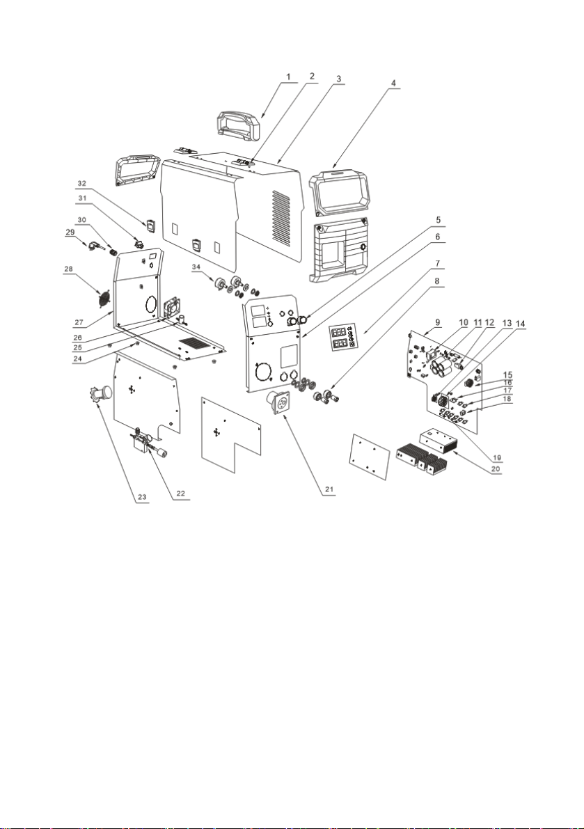
EXPLOSION MAP VIEW
- 12 -

- 13 -
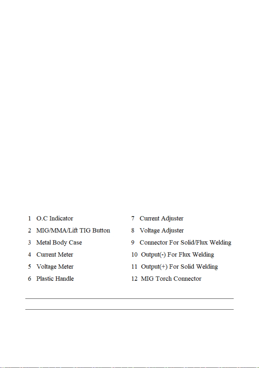
No Item No Item
1Plastic Handle 17 IGBT Tube
2Hinge 18 Drive Transformer
3Outer Body Shell 19 Fast-Recovery Diode
4Front Plastic Panel 20 Heat Sink
5Rotary Knob 21 Insulated Flange
6Front Panel 22 Wire Feeder
7Digital Meter 23 Coil Shaft
8Cable Connector 24 Foot Pad
9Main PC Board 25 Magnetic Valve
10 Power Transformer 26 Cooling Fan
11 Capacitor 470uF/400V 27 Rear Panel
12 Relay 30A 28 Fan Protection
13 Electric Reactor 29 Power Plug
14 Main Transformer 30 Power Line Connection
15 EMC Part 31 ON/OFF Switch
16 Rectifier Bridge 32 Door Holder

- 14 -
CHECK FAULT
Notes: If user wants to operate machine as following, the operator must
be a personnel in a specific field of electricity and safety and hold the
relevant certification that proves their ability and knowledge. Before
maintenance, contact with our sale agent for authorization is suggested.
Faults Resolvable Method
Power indicator
is not lit, fan
does not work
and no welding
output
1、Make sure air switch is closed.
2、Check if electric wire net is in work.
3、Some of heat-variable resistors(four) of power panel is
Damaged, when it happen, general DC24v relay is open or
Connectors are poor contact.
4、Power panel(bottom board) is damaged, DC 310V voltage
Cannot be output.
(1) Silicon bridge is broken or connector of silicon bridge
Poor contact.
(2) Power panel has been burned up.
(3) Check the wire from the power switch to input cable is poor
contact or not
5、Auxiliary power of control panel is in fault.
Power indicator
is lit, fan works,
no welding
output
1、Check if all kinds of cables of inter-machine are poor contact.
2、Output connector is cut off or poor contacted.
3、Control cable or switch of torch is broken.
4、Control circuit is broken.
Power indicator
is lit, fan works,
abnormal
indicator is lit.
1、Maybe it is overheated protection, please turn off machine first,
then turn on the machine again after abnormal indicator is
off.
2、Maybe it is overheated protection, wait for 2-3 minutes.
3、Maybe inverter circuit is in fault:

- 15 -
(1) If abnormal indicator is still lit, some of IGBT is damaged on
the main board, find out and replace it with same model.
(2) If abnormal indicator is not lit,:
a. Maybe transformer is damaged, measure inductance
volume and Q volume of main transformer by inductance
bridge.
b. Maybe secondary rectifier tube of transformer is damaged,
find out faults and replace rectifier tube with it.
Note: T
Th
he
eo
op
pe
er
ra
at
ti
io
on
ns
sb
be
el
lo
ow
wr
re
eq
qu
ui
ir
re
et
th
he
eo
op
pe
er
ra
at
to
or
rw
wi
it
th
he
en
no
ou
ug
gh
h
k
kn
no
ow
wl
le
ed
dg
ge
eo
of
fe
el
le
ec
ct
tr
ri
ic
ci
it
ty
ya
an
nd
do
ov
ve
er
ra
al
ll
lc
co
om
mm
mo
on
ns
se
en
ns
se
eo
of
fs
se
ec
cu
ur
ri
it
ty
y,
,
q
qu
ua
al
li
if
fi
ic
ca
at
ti
io
on
nc
ce
er
rt
ti
if
fi
ic
ca
at
te
ew
wh
hi
ic
ch
hc
ca
an
np
pr
ro
oo
of
ft
th
he
ei
ir
ra
ab
bi
il
li
it
ty
ya
an
nd
dk
kn
no
ow
wl
le
ed
dg
ge
ei
is
sa
a
n
ne
ec
ce
es
ss
sa
ar
ry
y.
.B
Be
ef
fo
or
re
et
th
he
ei
in
ns
sp
pe
ec
ct
ti
io
on
n,
,w
we
er
re
ec
co
om
mm
me
en
nd
dt
th
ha
at
ty
yo
ou
us
sh
ho
ou
ul
ld
d
c
co
on
nt
ta
ac
ct
tw
wi
it
th
hu
us
sa
an
nd
dg
ge
et
ta
ap
pp
pr
ro
ov
va
al
lf
fr
ro
om
mt
th
he
em
m.
.
CHECK FAULTS
When abnormal situation such as failure of welding, unstable arc, poor
welding result, do not consider that it must be some faults.
The machine may be well but just some reasons cause abnormality such as
that some connectors are loosened, forget to turn on the switch, wrong setting,
broken cable and gas pipe, etc. So before maintenance, Please check it up first,
some problem may be solved.
The following is earlier checking diagram by this way. In the top right corner
item you can find the problem, please check according to the diagram for the one
with “O” mark.
i

- 16 -
EARLIER CHECKING DIAGRAM FOR THEABNORMAL
The abnormal
Items to be checked
No arcing
No gas
Can’ t Send wire
Poor Arcing initiation
Unstable arc
Welding margin unclean
Wire and Material conglutinated
Wire links Electric leading hole
fcon conglutinated
Have air hole
Power
supply
box
(input
protectiv
e set)
1、
connected or not
2、Fuse broken
3、Connector loosen 〇 〇 〇 〇 〇 〇
Input
cable
1、Broken or not
2、Connector
loosen
3、Over-heat
〇 〇 〇 〇 〇 〇
Power 1、Switched or not
2、Lack phase 〇 〇 〇 〇 〇 〇 〇 〇
Gas
Cylinder
And
adjuster
1、Open cover
2、Remains of gas
3、low setting volume
4、Connecting point
loosen
〇 〇
Gas pipe
(access
from the
high-pres
sure
cylinder
to torch)
1、Connecting point
loosen
2、Pipe broken 〇

- 17 -
Wire
sending
equipme
nt
1、Wheel and
leading tube not
match
2、Wheel broken,
slot blocked or
lack
3、Over pressing or
loosen, powder
store up in
entrance of SUS
tube
〇 〇 〇 〇 〇
DAILY CHECKING
Position Checking keys Remarks
Control
panel
1.Switch condition of operation,
transfer and installment.
2.Test the power indicator
Cooling fan 1.Check if there is wind and the
sound normal or not. If abnormal noise and no
wind, to check the inner.
Power part
1.When electrified, abnormal smell
or not.
2.When electrified, abnormal
vibration and buzz or not.
3.Color changing and heating or
not in appearance.
Periphery 1.Gas pipe broken, loosen or not.
2.Housing and other fixed parts
loosen or not.
WELDING POWER S
UPPLY

- 18 -
Position Checking keys Remarks
Loophole
1.If installment fixed, the front
distorted Reason for air hole.
2.Attach splash or not. Reason for burning the torch.
(Can use the splash-proof
material)
Electric
hole
1.If installment fixed Reason of torch screw thread
damage
2.damage of its head and hole
blocked nor not Reason of unstable arc and
broken arc
Wire
sending
tube
1.check the extended size of
the pipe
Have to be changed when less
than 6mm, when the extended
part too small, the arc will be
unstable.
2.Wire diameter and the tube
inner diameter match or not Reason of unstable arc,
please use the suitable tube.
3.Partial winding and extended Reason of poor wires sending
and unstable arc, please
change.
4.Block caused by dirt in the
tube, and the remains of the
wire plating lay.
Reason of poor wire sending
and unstable arc, (use
kerosene to wipe or change
new one.)
5.Wire sending tube broken
O circle wear out
1.Pyrocondensation tube
broken, change new tube
2.Change new O circle
Gas
bypass
Forget to insert or the hole
blocked, or different factory
component.
May lead to vice (splash)
because of poor gas shield,
torch body get burned (arc in
the torch), please handle.
WELDING TORCH

- 19 -
Position Checking keys Remarks
Pressing
arm
1.If put the arm to the suitable
indicating level.
(notes:not to damage wire less
than Ф1.0mm )
Lead to unstable arc and wire
sending.
Wire
Lead
Tube
1.If powder or residue store up
in the mouth of the tube. Clean the residue and check the
reason and solve it.
2.Wire diameter and the tube
inner diameter match or not If not match, lead to unstable arc
and residue.
3.If the tube mouth center
matches the wire wheel slot
center or not.
If unmatched, lead to unstable
arc and residue.
Wire
wheel
1.Wire diameter matches the
wheel’s requirement
2.If the wheel slot blocked
1.Lead to unstable arc and
residue, and block wire tube.
2.Change new one if necessary
Pressure
wheel
Check the stability of its move,
and wearing-out of pressed wire,
the narrowing of its contact
surface
Lead to unstable arc and wire
sending.
WIRE SENDING MACHINE

- 20 -
Position Checking keys Remarks
Torch
cable
1.If torch cable over bended.
2.If the metal connecting point of
mobile plug loosen
1. Cause poor wire sending
2. Unstable arc if cable over
bended.
Output
cable
1. Wearing-out of the cable
insulated material.
2.Cable connecting head naked
(insulation damage), or loosen
(the end of power supply, and
cable of main material connecting
point.)
For life security and
stable welding, adopt
suitable method to
check according to
working place.
Simple check daily
Careful and in-depth
check on fixed periodInput
cable
1.If the connect of power supply
input, protective equipment input
and the output end fixed or not.
2.If the security equipment cable
reliably connected.
3.If the power input end cable fixed
4.If the input cable is worn out and
bares the conductor.
Earth
cable
1.If the earth cable that connects
the power supply is broken and
connect tightly.
2.If the earth cable that connects
the main part is broken and
connects tightly.
To prevent creep age and
insure security, please make
daily check.
CABLE
Table of contents
Other IGBT Welding System manuals


Popular Welding System manuals by other brands


Koike Sanso Kogyo
Koike Sanso Kogyo IK-72T Operation manual

Lincoln Electric
Lincoln Electric Mobiflex 200-M Operator's manual

LENCO
LENCO L-6000 LENCOSPOT MARK III manual

ESAB
ESAB Origo Mig 4002cw Service manual

EWM
EWM Taurus 355 Synergic S LP MM TKM operating instructions

ESAB
ESAB EMP 255ic Service manual


