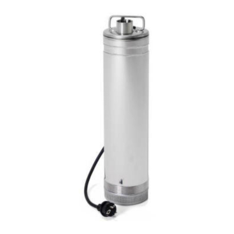
umbra pompe ACUAFLUSS 4 Installation and operating instructions

ACUAFLUSS 4”
ACUAFLUSS 5”
ACUAFLUSS L
TECHNICAL ADDENDUM
Submersible motor pumps Acuafluss
GB
ADDENDUM TECHNIQUE
Pompe à moteut submersible Acuafluss
F
ADDENDUM TECNICO
Elettropompe sommerse Acuafluss
I
TECHNISCHER NACHTRAG
Tauchmotorpumpe Acuafluss
D
ANEXO TECNICO
Motobomba Sumergible Acuafluss
E
وكينكت ةفاضإ
Acuafluss ةسطاغ ةخضم
KSA
ТЕХНИЧЕСКОЕ ПРИЛОЖЕНИЕ
Электрические погружные насосы Acuafluss
RUS


ENGLISH
1.1 General instructions
1.1.1 This technical Addendum contain specific informations for Acuafluss submersible pumps,
complementary to the instruction manual. Comply with the indications written in both parts to
obtain the correct operation of the pump. In case in the two manuals you find informations in
contrast, you must follow the indications written here.
2.1 Application
2.1.1 Multistage electric submersible pumps with electronic parts integrated, with electronic
pressure regulator and check valve. This pump has been realized in order to start and stop the
pump according to the flow level to avoid to use the pump without water. The ideal application is
in the rainwater system, irrigation, to pump clean water from tank, tanks, wells and other
applications where is required an high pressure.
2.1.2 With a water require bigger than 1,5 l/min. the pump remain always in operation.
2.2 Application limit
2.2.1 The starting pressure for the model Acuafluss 30 is around 1,5bar; in the other models
(Acuafluss 40, 60, 55/60 and 100/70) is around 2,5 bar. This fact surely limit the geometric height
where you can put the pump respect the highest point of the circuit that will be of 10m for
Acuafluss 30 and 20m for the other models (see ANNEX "A" fig.2). As long as there is even one
tap open, the pump remain in operation, when all the taps are closed the pump will stop.
3.1 Installation
3.1.1 Respect the assembly instructions indicated in the ANNEX A fig.1. and 2. The
geometric height from the pump position to the highest point of the system should not
exceed 10m for Acuafluss 30 and 20m for the other models.
3.1.2 The Acuafluss pumps have an in-built check valve, please don’t use other valves.
3.1.3 To use the ACUAFLUSS pump in the right way is absolutely necessary to install an
expansion vessel (minimum 3lt of capacity) wherever you prefer in the charge piping (see
ANNEX A fig. 1 and 2. ). Remember to check periodically the vessel pressure. If there isn’t
this vessel you may have a problem due to the excess of maximum numbers of
intervention allowed (40/h) that can block the pump.
3.2 Use
3.2.1 For ACUAFLUSS pumps wait approximately 10 seconds for self-priming. In the event that
the integrated electronic notice that there is no water the pump will stop.The system will try for
another 4 times to start the pump every 15 min. in the first hour of operation. If no one attempt
permit to notice water, the pump will continue to try every 1 hour for the next 48 hours. After this,
you have to start-up manually the system (disconnecting and connecting the electricity supply ).
3.2.2 The pump is able to recognise eventual blockage of non return valve due to limestone and
limescale or sand. In the event that the valve is blocked the electronic will stop the pump that can
GB
TECHNICAL ADDENDUM
Electric submersible pumps Acuafluss
1. INTRODUCTION
2. APPLICATIONS AND LIMITS
3. INSTALLATION AND USE

ENGLISH
be activated again only if you remove the problem and start-up manually the system
( disconnecting and connecting the electricity supply ).
See ANNEX “C”.
See ANNEX “B”.
FAULT
POSSIBLE CAUSE
REMEDY
1.
PUMP DOESN’T DELIVER,
a.
No voltage
a.
Check the connection
MOTOR DOESN’T START
b.
Plug not properly inserted
b.
Check for power in mains and insert
correctly the plug
c.
Circuit braker switch intervened
c.
Switch on the magnetothermal
d.
Impeller blocked
d.
Make sure impeller rotates freely
e.
Motor or capacitor damaged
e.
Contact the supplier
f.
Check valve blocked
f.
Remove the obstruction, disconnecting
And connecting again the electricity
supply
g.
No water
g.
Restore the water level
2.
PUMP DOESN’T DELIVER,
a.
The head you need is higher than the
a.
Respect the characteristics on the label
MOTOR IS RUNNING
characteristics of the pump
Of the pump
b.
The geometric heigh from the pump
b.
Respect the maximum geometric heigh
position to the highest point of the
as you can see on the installation manual
system is to high
3.
PUMP DELIVER A LOWER
a.
Grid or suction filter obstricted
a.
Clean it
FLOW RESPECT
b.
Delivery pipe partly obstricted
b.
Remove the eventually obstructions
THAT DECLARATED
c.
Impeller worn
c.
Contact the supplier to replace it
ON THE DATA CURVES
d.
The rotation direction is wrong
d.
Check the sense of rotation
(only on tree-phase versions)
and eventually inverti t.
4.
PUMP DOESN’T STOP
a.
The supply switch is defective
a.
Replace it
b.
You didn’t install the expansion vessel
b.
Install the expansion vessel
c.
Has been left a tap open or there is a
c.
Verify that all the tap are closed and the
lake in the charge piping
Presence of a lake in the charge piping
5.
INTERMITTENT
a.
The pump is partly blocked by impurities
a.
Remove the eventually impurities
OPERATION
that blocked the impeller
On hydraulic part
b.
Temperature or density of liquid to be
b.
Check the condition of the liquid to be
pumped too high
pumped
c.
Motor defective
c.
Contact the supplier to replace it.
6.
THE OVERLOAD
a.
The motori is overheating
a.
Verify the possible reasons that bring
PROTECTION DEVICE
the motor to hight temperature and
STOP THE PUMP
remove it
b.
The pump is mechanically blocked
b.
Checking for the occurrence of rubbing
Between moving and fixed parts, check
The state of mechanical seal and
bearings
4. CONFORMITY DECLARATION
5. TECHNICAL DOCUMENTATION
6. TROUBLESHOOTING
INCONVENIENTI
CAUSE
RIMEDI
1.
LA POMPA NON EROGA,
a.
Mancanza di tensione
a.
Verificare le connessioni
IL MOTORE NON GIRA
b.
Spina non bene inserita
b.
Verificare la presenza di elettricità
e inserire bene la spina
c.
Interruttore differenziale intervenuto
c.
Riarmare l'interruttore
d.
Girante bloccata
d.
Liberare la girante dalle possibili
ostruzioni
e.
Motore o condensatore danneggiato
e.
Contattare rivenditore
f.
Valvola di ritegno interna bloccata
f.
Rimuovere l'ostruzione, disinserire e
reinserire l'alimentazione
g.
Mancanza di acqua
g.
Ripristinare il livello dell'acqua
2.
LA POMPA NON EROGA,
a.
La prevalenza richiesta è superiore
a.
Consultare e rispettare le caratteri-
IL MOTORE GIRA
alle caratteristiche della pompa
stiche della pompa
b.
L'altezza geometrica tra il punto di
b.
Verificare il rispetto dell'altezza geo-
richiesta dell'acqua e il punto di in-
metrica massima riportato sullo
stallazione della pompe è eccessiva
schema di installazione
3.
LA POMPA EROGA
a.
Griglia aspirazione e/o filtro ostruiti
a.
Pulire griglia e/o filtro
UNA PORTATA
b.
Tubazione di mandata parzialmente
b.
Rimuovere le eventuali ostruzioni
INFERIORE RISPETTO
ostruita
A QUELLA DICHIARATA
c.
Girante usurata
c.
Contattare assistenza per la sostitu-
DALLE CURVE
zione
d.
Il senso di rotazione non è corretto
d.
Verificare che il senso di rotazione
(nelle sole versioni trifase)
sia rispettato ed eventualmente
invertirlo
4.
LA POMPA NON SI
a.
L'interruttore di alimentazione è
a.
Sostituire l'interruttore a monte
ARRESTA
difettoso
b.
Non è stato installato il vaso di
b.
Installare vaso di espansione
espansione sul circuito di mandata
c
.
E' stata lasciata una utenza aperta o
c.
Verificare che tutte le utenze siano
è presente una perdita nell'impianto
chiuse e non ci siano perdite
5.
FUNZIONAMENTO
a.
Corpi solidi impediscono la libera
a.
Rimuovere le eventuali ostruzioni
INTERMITTENTE
rotazione della girante
b.
Temperatura del liquido da pompare
b.
Verificarele condizioni del liquido
o densità troppo alte
da pompare
c.
Motore difettoso
c.
Contattare assistenza per la sostitu-
zione
6.
IL DISPOSITIVO DI
a.
L'assorbimento del motore è troppo
a.
Varificare le eventuali cause che
PROTEZIONE
elevato
portano il motore ad un eccessivo
MAGNETOTERMICO
sforzo e conseguente surriscalda-
ARRESTA LA POMPA
mento
b.
L'elettropompa è bloccata meccani-
b.
Controllare il verificarsi di striscia-
camente
mento tra parti mobili e fisse, con-
trollare lo stato di usura dei cusci-
netti
7. POSSIBILI AVARIE, MOTIVI E SOLUZIONI

FRANÇAIS
1.1 Dispositions générales
1.1.1 Ce Addendum técnique, complémentaire au manuel d’instructions, comprend les informations
spécifiques pour les électropompes de la série Acuafluss. Suivez les indications décrites dans les
deux fascicules pour obtenir un fonctionnement correct de l’électropompe. Au cas où vous
trouverez des informations opposées dans les deux manuels, suivez les indications de ce
Addendum técnique.
2.1 Emploi
2.1.1 Electropompes immergées à plusieurs étages complètes d’électronique, munies de
regulateur de pression et clapet anti retour. Cette pompe a été developpée pour automatiser le
démarrage et l’arrêt de la pompe selon la quantité d’eau demandé par l’utilisateur et pour éviter
le fonctionnement en absence de liquide. Particulièrement indiqée dans les systèmes pour
récupérer l’eau de pluie, réseaux d’irrigation, pompage d’eau claire de réservoirs, citernes, puits
et pour autres applications qui ont besoin d’une haute pression.
2.1.2 Avec une demande d’eau supérieur à environ 1,5 l/min. la pompe reste toujours en
marche.
2.2 Limites d’emploi
2.2.1 La pression de démarrage pour le modèle Acuafluss 30 est 1,5bar; pour d’autres modèles
s’obtient à environ 2,5 bar. Ceci limite l’hauteur géométrique où la pompe peut être positionnée
par rapport au point le plus haut de l'installation qui résulte être de 10m pour le modèle
Acuafluss 30 et 20m pour d’autres modèles, (voire ANNEX "À" fig.2) Tant qu'il y a au moins un
robinet ouvert la pompe restera en marche ; une fois fermée tous les robinets la pompe
s'arrêtera.
3.1 Installation
3.1.1 Respecter les schémas d'assemblage reportés dans l’ANNEX "À" fig. 1 et 2.
L'hauteur géométrique de la position de la pompe au point le plus haut de l'installation ne
doit pas dépasser les 10 m pour le modèle Acuafluss 30 et 20m pour d’autres modèles.
3.1.2 Les modèles Acuafluss sont déjà équipé d’un clapet anti retour à bord de la
machine, n’installez pas d’autres clapets.
3.1.3 Pour le fonctionnement des elettropompes Acuafluss il est impérativement
nécessaire installer un vase ou pot d'expansion (d’une capacité d’au moins 3lt) dans un
point quelconque de la conduite de refoulement. (voire ANNEX "À" fig. 1 et 2). Rappelez-
vous de vérifier périodiquement le surpression du susdit vase. L’absence de ce
composant pourrait porter à dépasser le numéro maximum de démarrages permis (40/h)
en envoyant la pompe en bloc.
3.2 Utilisation
3.2.1 Pour les modèles Acuafluss il faut attendre à peu près 10 seconds pour l’amorçage. Si
l’électronique intégré relève un manque d’eau, l’électropompe s’arrête. Le circuit effectuera 4
F
ADDENDUM TECNIQUE
Electropompes immergées Acuafluss
1. INTRODUCTION
2. APPLICATIONS ET LIMITES D’EMPLOI
3. INSTALLATION ET UTILISATION

FRANÇAIS
autres essais d’allumage avec des intervalles regulièrs de 15min pendant la première heure de
fonctionnement. En cas d’absence d’eau pendant cette periode, les essias seront faits chaque
heure pour les prochaines 48 heuers. Par la suite, il sera nécessaire de réactiver le circuit
manuellement (débranchez et re-insérez l’alimentation électrique).
3.2.2 L’électropompe peut reconnaitre si le clapet anti retour s’enraye à cause du calcaire et
incrustations ou sable. Si le clapet result enrayé, l’électronique de control envoie la pompe en
bloc. Il sera possible de faire repartir la pompe seulement après avoir enlevé les causes de
l’obstruction et en activant le circuit manuellement (débranchez et re-insérez l’alimentation
électrique).
Voir ANNEX “C”.
Voir ANNEX “B”.
PANNES
CAUSES
REMEDES
1.
LA POMPE NE VOUS
a.
Le manque d’électricité
a.
Vérifiez les joints
LIVRE L’EAU, LE MOTEUR
b.
Fiche non correctement insérée
b.
Vérifiez l’électricité dans la prise et
NE TOURNE PAS
branchez la fiche électrique
c.
Interrupteur différentiel est intervenu
c.
Réarmez le commutateur
d.
La roue est bloquée
d.
Libérez la roue de possible obstructions
e.
Moteur ou condensateur endommagé
e.
Contactez le revendeur
f.
Clapet anti retour bloquée
f.
Retirer les causes de l’obstruction,
débranchez et re-insérez l’alimentation
èlectrique
g.
Absence de liquide
g.
Rétablir le niveau de l’eau
2.
LA POMPE NE REFOULE
a.
La requis de l’hauteur est supérieur aux
a.
Consulter et respecter les caractéristi-
PAS, LE MOTEUR
caractéristiques de la pompe
ques de la pompe
TOURNE REGULIEREMENT
b.
L’hauteur géométrique de la position de
b.
Vérifiez la conformité de l’hauter géomé-
la pompe au poit de l’installation est
trique maximale rapport sur le schéma
excessif
d’installation
3.
LA POMPE FOURNIT
a.
Filtre ou grille obstrué
a.
Nettoyez la grille et/ou le filtre
UN DÉBIT D’ECOULEMENT
b.
Tuyau partiellement obstrué
b.
Enlevez les obstacles
PLUS FAIBLE QUE
c.
Roue usurée
c.
Contactez le revendeur pour le
CE DECLARE
remplacement
d.
Sens de rotation incorrect
d.
Vérifiez et éventuellement inversez
(seulement pour la version triphasée)
le sens de rotation
4.
LA POMPE NE S’ARRETE
a.
Interrupteur d’alimentation défectueux
a.
Remplacez l’interrupteur
PAS
b.
Pas installé un vase ou pot d’expansion
b.
Installer un vase ou pot d’expansion
c.
Est présent un utilisateur ouverte
c.
Assurez-vous que tous le utilisateurs sont
fermé
5.
FONCTIONNEMENT
a.
Solides empêchent la libre rotation de la
a.
Enlevez les obstacles
INTERMITTENT
roue à aubes
b.
Température du liquide ou densité trop
b.
Vérifiez l’ètat du liquide à pomper
élevée
c.
Moteur défectueux
c.
Contactez le revendeur pour le
remplacement
6.
LE DISPOSITIF DE
a.
Absorbtion du moteur trop élevée
a.
Vérifiez les causes qui conduisent
PROTETION
le moteur à faire un effort trop élevé avec
THERMO-AMPEREMETRIQUE
consécutif surchauffer
ARRETE L’ELECTROPOMPE
b.
L’électropompe est bloquée
b.
Controlez les frottements entre parties
mécaniquement
mobiles et parties fixes.
Contrȏlez l’ètat d’usure des
roulements
4. DÉCLARATION DE CONFORMITÉ
5. DOCUMENTATION TECHNIQUE
6. IDENTIFICATION DES INCONVÉNIENTS ET REMÉDES
INCONVENIENTI
CAUSE
RIMEDI
1.
LA POMPA NON EROGA,
a.
Mancanza di tensione
a.
Verificare le connessioni
IL MOTORE NON GIRA
b.
Spina non bene inserita
b.
Verificare la presenza di elettricità
e inserire bene la spina
c.
Interruttore differenziale intervenuto
c.
Riarmare l'interruttore
d.
Girante bloccata
d.
Liberare la girante dalle possibili
ostruzioni
e.
Motore o condensatore danneggiato
e.
Contattare rivenditore
f.
Valvola di ritegno interna bloccata
f.
Rimuovere l'ostruzione, disinserire e
reinserire l'alimentazione
g.
Mancanza di acqua
g.
Ripristinare il livello dell'acqua
2.
LA POMPA NON EROGA,
a.
La prevalenza richiesta è superiore
a.
Consultare e rispettare le caratteri-
IL MOTORE GIRA
alle caratteristiche della pompa
stiche della pompa
b.
L'altezza geometrica tra il punto di
b.
Verificare il rispetto dell'altezza geo-
richiesta dell'acqua e il punto di in-
metrica massima riportato sullo
stallazione della pompe è eccessiva
schema di installazione
3.
LA POMPA EROGA
a.
Griglia aspirazione e/o filtro ostruiti
a.
Pulire griglia e/o filtro
UNA PORTATA
b.
Tubazione di mandata parzialmente
b.
Rimuovere le eventuali ostruzioni
INFERIORE RISPETTO
ostruita
A QUELLA DICHIARATA
c.
Girante usurata
c.
Contattare assistenza per la sostitu-
DALLE CURVE
zione
d.
Il senso di rotazione non è corretto
d.
Verificare che il senso di rotazione
(nelle sole versioni trifase)
sia rispettato ed eventualmente
invertirlo
4.
LA POMPA NON SI
a.
L'interruttore di alimentazione è
a.
Sostituire l'interruttore a monte
ARRESTA
difettoso
b.
Non è stato installato il vaso di
b.
Installare vaso di espansione
espansione sul circuito di mandata
c
.
E' stata lasciata una utenza aperta o
c.
Verificare che tutte le utenze siano
è presente una perdita nell'impianto
chiuse e non ci siano perdite
5.
FUNZIONAMENTO
a.
Corpi solidi impediscono la libera
a.
Rimuovere le eventuali ostruzioni
INTERMITTENTE
rotazione della girante
b.
Temperatura del liquido da pompare
b.
Verificarele condizioni del liquido
o densità troppo alte
da pompare
c.
Motore difettoso
c.
Contattare assistenza per la sostitu-
zione
6.
IL DISPOSITIVO DI
a.
L'assorbimento del motore è troppo
a.
Varificare le eventuali cause che
PROTEZIONE
elevato
portano il motore ad un eccessivo
MAGNETOTERMICO
sforzo e conseguente surriscalda-
ARRESTA LA POMPA
mento
b.
L'elettropompa è bloccata meccani-
b.
Controllare il verificarsi di striscia-
camente
mento tra parti mobili e fisse, con-
trollare lo stato di usura dei cusci-

DEUTSCH
1.1 Allgemeine Bestimmungen
1.1.1 Dieser technische Nachtrag enthält spezifische Informationen für die Elektropumpen der
Baureihe Acuafluss, die die Betriebsanleitung ergänzen. Halten Sie sich an die Anweisungen auf
beiden Seiten, um die korrekte Funktion der Elektropumpe zu gewährleisten. Wenn die beiden
Handbücher widersprüchliche Informationen enthalten, befolgen Sie die Anweisungen in diesem
technischen Nachtrag.
2.1 Anwendung
2.1.1 Mehrstufige elektrische Tauchpumpe mit integrierter Elektronik, ausgestattet mit
Druckregler und Rückschlagventil. Diese Pumpe wurde entwickelt, um das Starten und Stoppen
der Pumpe entsprechend dem Wasserbedarf des Benutzers zu automatisieren und den Betrieb
ohne Flüssigkeit zu vermeiden. Es ist ideal für den Einsatz in
Regenwasserrückgewinnungssystemen, Bewässerungsnetzen, beim Pumpen von sauberem
Wasser aus Tanks, Zisternen, Brunnen und anderen Anwendungen, die einen hohen Druck
erfordern.
2.1.2 Bei einem Wasserbedarf von mehr als ca. 1,5 l/Min. bleibt die Pumpe jederzeit in Betrieb.
2.2 Einsatzgrenzen
2.2.1 Der Startdruck beträgt beim Modell Acuafluss 30 1,5 bar, mit den anderen Modellen
(Acuafluss 40, 60, 55/60 und 100/70) ca. 2,5 bar. Dies begrenzt die geometrische Höhe, in der
die Pumpe in Bezug auf den höchsten Punkt des Systems positioniert werden kann, der bei den
Versionen Acuafluss 30 10m bei den anderen Modellen ist es 20m. (siehe ANHANG „A“ Abb. 2).
Solange mindestens ein Wasserhahn geöffnet ist, bleibt die Pumpe in Betrieb; sobald alle
Wasserhähne geschlossen sind, stoppt sie.
3.1 INSTALLATION
3.1.1 Beachten Sie die Installationspläne im ANHANG „A“ Abb. 1 und 2. Die geometrische
Höhe von der Position der Pumpe bis zum höchsten Punkt des Systems darf 10m bei
Acuafluss 30 und 20m in den anderen Modellen nicht überschreiten.
3.1.2.1 Acuafluss-Modelle sind bereits mit einem Rückschlagventil an Bord der Maschine
ausgestattet, installieren Sie keine anderen Ventile.
3.1.3 Für den Betrieb von Acuafluss-Elektropumpen ist es unbedingt erforderlich, an jeder
Stelle der Druckleitung ein Ausdehnungsgefäß oder einen Behälter mit einem
Fassungsvermögen von mindestens 3 Litern zu installieren (siehe ANHANG „A“ Abb. 1
und 2). Denken Sie daran, die Druckbeaufschlagung dieses Behälters regelmäßig zu
überprüfen. Das Fehlen dieser Komponente würde dazu führen, dass die maximale
Anzahl der zulässigen Starts (40/h) überschritten würde, wenn die Pumpe im Block
gesendet würde.
3.2 Nutzung
3.2.1 Die Acuafluss-Modelle warten etwa 10 Sekunden auf die Priming-Phase. Erkennt die
integrierte Elektronik einen Wassermangel, stoppt die Elektropumpe. Die Schaltung führt in der
DE
TECHNISCHER NACHTRAG
Elektrische Tauchpumpen Acuafluss
1. EINLEITUNG
2. ANWENDUNGEN UND EINSCHRÄNKUNGEN FÜR DIE VERWENDUNG
3. INSTALLATION UND VERWENDUNG

DEUTSCH
ersten Betriebsstunde in regelmäßigen Abständen von 15 Minuten 4 zusätzliche Zündversuche
durch. Wenn es in keinem der Versuche gelingt, das Vorhandensein von Wasser zu erkennen,
wird es weiterhin jede Stunde für die folgenden 48 Stunden einen Versuch durchführen. Der
Stromkreis muss dann manuell neu gestartet werden (durch Aus- und Einschalten der
Stromversorgung).
3.2.2 Die Elektropumpe ist in der Lage, ein Blockieren des Rückschlagventils durch Kalk und
Verkrustungen oder Sand zu erkennen. Im Falle eines Ventilstaus blockiert die Steuerelektronik
die Pumpe. Sie kann erst wieder gestartet werden, nachdem die Ursache der Behinderung
beseitigt und die Schaltung manuell (durch Aus- und Einschalten der Stromversorgung) wieder
aktiviert wurde.
SIEHE ANHANG „C“.
Siehe ANHANG „B“.
4. KONFORMITÄTSERKLÄRUNG
5. ZUSÄTZLICHE TECHNISCHE DOKUMENTATION

DEUTSCH
PROBLEME
URSACHEN
LÖSUNGEN
1.
DIE PUMPE FÖRDERT
NICHT,
a.
Fehlende Spannung
a.
Überprüfen sie die Verbindungen.
DER MOTOR LÄUFT
NICHT
b.
Stecker nicht richtig eingesteckt
b.
Überprüfen Sie, ob Strom vorhanden ist
und stecken Sie den Stecker richtig ein.
c.
FI-Schutzschalter ausgelöst
c.
Zurücksetzen des Schalters
d.
Laufrad blockiert
d.
Befreien Sie das Laufrad vom möglichen
Verstopfungen.
e.
Beschädigter Motor oder Kondensator
e.
Kontaktieren Sie den Händler.
f.
Internes Rückschlagventil blockiert
f.
Entfernen Sie die Verstopfung, trennen
Sie es und
schalten Sie die Stromversorgung wieder
ein.
g.
Wassermangel
g.
Herstellen Sie den Wasserstand wieder.
2.
DIE PUMPE FÖRDERT
NICHT,
a.
Die erforderliche Prävalenz ist höher
a.
Beraten Sie und halten Sie die
Eigenschaften der
DER MOTOR LÄUFT
als die Eigenschaften der Pumpe.
Pumpe ein.
b.
Die geometrische Höhe zwischen dem
Wasserbedarfsstelle
b.
Überprüfen Sie, ob die im
Installationsplan
und der Pumpenaufstellungsort
angegebene maximale
ist zu hoch.
geometrische Höhe respektiert wurde.
3.
DIE PUMPE FÖRDERT
a.
Verstopfte Ansaug- und/oder Filtergitter
a.
Reinigen Sie Gitter und/oder Filter.
EINE NIEDRIGERE
b.
Förderleitung teilweise
b.
Entfernen Sie alle Verstopfungen.
MENGE
verstopft
ALS DIEJENIGE, DIE VON
DEN KURVEN
c.
Laufrad verschlissen
c.
Kontaktieren Sie die Kundendienststelle
für den
ERKLÄRT WURDE
Austausch.
d.
Die Drehrichtung ist nicht korrekt
d.
Überprüfen Sie die Einhaltung
(nur in den dreiphasigen Versionen).
der Drehrichtung und kehren Sie
diese gegebenenfalls um.
4.
DIE PUMPE STOPPT
a.
Der Netzschalter ist
a.
Ersetzen Sie den vorgeschalteten
Schalter.
NICHT
defekt.
b.
Das Ausdehnungsgefäß ist nicht auf
b.
Installieren Sie das Ausdehnungsgefäß.
dem Förderkreislauf installiert.
c.
Eine offene Benutzung wurde
zurückgelassen oder
c.
Überprüfen Sie, ob alle
Versorgungsleitungen
es liegt ein Leck im System vor.
geschlossen sind und keine Lecks
vorhanden sind.
5.
TAKT-
a.
Festkörper verhindern eine freie
a.
Entfernen Sie alle Verstopfungen.
BETRIEB
Rotation des Laufrades.
b.
Temperatur der zu fördernden
Flüssigkeit
b.
Überprüfen Sie den Zustand der
oder zu hohe Dichte
zu fördernden Flüssigkeit.
c.
Defekter Motor
c.
Kontaktieren Sie die Kundendienststelle
für den
Austausch.
6.
DIE
MAGNETOTHERMISCHE
a.
Die Motoraufnahme ist zu
a.
Überprüfen Sie die möglichen Ursachen,
SCHUTZVORRICHTUNG
Hoch.
die den Motor zu übermäßiger Belastung
und damit
BLOCKIERT
zu Überhitzung
DIE PUMPE
führen.
b.
Die elektrische Pumpe ist mechanisch
b.
Überprüfen Sie das Auftreten von
Gleitbewegungen
blockiert.
zwischen beweglichen und festen Teilen,
überprüfen Sie den Verschleißzustand
der
Lager.
6. MÖGLICHE AUSFÄLLE, GRÜNDE UND LÖSUNGEN
PROBLEME
URSACHEN
LÖSUNGEN
1.
DIE PUMPE FÖRDERT
NICHT,
a.
Fehlende Spannung
a.
Überprüfen sie die Verbindungen
DER MOTOR LÄUFT
NICHT
b.
Stecker nicht richtig eingesteckt
b.
Überprüfen Sie, ob Strom vorhanden ist
und stecken Sie den Stecker richtig ein
c.
FI-Schutzschalter ausgelöst
c.
Zurücksetzen des Schalters
d.
Laufrad blockiert
d.
Befreien Sie das Laufrad vom möglichen
Verstopfungen
e.
Beschädigter Motor oder Kondensator
e.
Händler kontaktieren
f.
Internes Rückschlagventil blockiert
f.
Entfernen Sie die Verstopfung, trennen
Sie sie es und
schalten Sie die Stromversorgung wieder
ein
g.
Wassermangel
g.
Herstellen Sie den Wasserstand wieder
2.
DIE PUMPE FÖRDERT
NICHT,
a.
Die erforderliche Prävalenz ist höher
a.
Beraten Sie und halten Sie die
Eigenschaften der
DER MOTOR LÄUFT
als die Eigenschaften der Pumpe
Pumpe ein
b.
Die geometrische Höhe zwischen dem
Wasserbedarfsstelle
b.
Überprüfen Sie, ob die im
Installationsplan
und der Pumpenaufstellungsort
angegebene maximale
ist zu hoch
geometrische Höhe
3.
DIE PUMPE FÖRDERT
a.
Verstopfte Ansaug- und/oder Filtergitter
a.
Gitter und/oder Filter reinigen
EINE UNTERE
b.
Förderleitung teilweise
b.
Entfernen Sie alle Verstopfungen
TÜRÖFFNUNG
verstopft
ALS DIEJENIGE DIE VON
DEN KURVEN
c.
Laufrad verschlissen
c.
Kontaktieren Sie die Kundendienststelle
für den
ERKLÄRT WURDE
Austausch
d.
Die Drehrichtung ist nicht korrekt
d.
Überprüfen Sie die Einhaltung
(nur in den dreiphasigen Versionen)
der Drehrichtung und kehren Sie
diese gegebenenfalls um
4.
DIE PUMPE STOPPT
a.
Der Netzschalter ist
a.
Ersetzen Sie den vorgeschalteten
Schalter.
NICHT
defekt
b.
Das Ausdehnungsgefäß ist nicht auf
b.
Installieren Sie das Ausdehnungsgefäß.
dem Förderkreislauf installiert.
C
...
Ein offener Benutzer wurde
zurückgelassen oder
c.
Überprüfen Sie, ob alle
Versorgungsleitungen
es liegt ein Leck im System vor.
geschlossen sind und keine Lecks
vorhanden sind
5.
TAKT-
a.
Festkörper verhindern eine freie
a.
Entfernen Sie alle Verstopfungen
BETRIEB
Rotation des Laufrades.
b.
Temperatur der zu fördernden
Flüssigkeit
b.
Überprüfen Sie den Zustand der
oder zu hohe Dichte
zu fördernden Flüssigkeit.
c.
Defekter Motor
c.
Kontaktieren Sie die Kundendienststelle
für den
Austausch
6.
DIE
MAGNETOTHERMISCHE
a.
Die Motoraufnahme ist zu
a.
Überprüfen Sie die möglichen Ursachen
SCHUTZVORRICHTUNG
hoch.
die den Motor zu übermäßiger Belastung
und damit
BLOCKIERT
zu Überhitzung
DIE PUMPE
führen.
b.
Die elektrische Pumpe ist mechanisch
b.
Überprüfen Sie das Auftreten von
Gleitbewegungen
blockiert.
zwischen beweglichen und festen Teilen,
überprüfen Sie den Verschleißzustand
der
Lager.
7. MÖGLICHE AUSFÄLLE, GRÜNDE UND LÖSUNGEN

ITALIANO
1.1 Disposizionei generali
1.1.1 Il presente Addendum Tecnico contiene informazioni specifiche per le elettropompe della
serie Acuafluss, complementari al Manuale di Istruzioni. Attenersi alle indicazioni riportate in
entrambe le parti per ottenere il corretto funzionamento dell’elettropompa. Qualora nei due
manuali siano presenti delle informazioni contrastanti tra loro, attenersi alle indicazioni del
presente Addendum Tecnico.
2.1 Impiego
2.1.1 Elettropompa sommersa multistadio con elettronica integrata, munita di regolatore di
pressione e valvola di ritegno. Tale pompa è stata sviluppata per automatizzare l’avvio e l’arresto
della pompa in funzione della richiesta d’acqua da parte dell’utilizzatore e per evitare il
funzionamento in assenza di liquido. Trova impiego ideale nei sistemi di recupero dell’acqua
piovana, reti di irrigazione, pompaggio di acqua pulita da serbatoi, cisterne, pozzi e per altre
applicazioni che richiedono un elevata pressione.
2.1.2 Con una richiesta d’acqua superiore a ca.1,5l/min la pompa resta sempre in funzione.
2.2 Limiti d’impiego
2.2.1 La pressione di avviamento nel modello Acuafluss 30 è di 1,5bar; nei restanti modelli
(Acuafluss 40, 60, 55/60 e 100/70) si ottiene a ca.2,5 bar. Ciò limita l’altezza geometrica dove
può essere posizionata la pompa rispetto al punto più alto dell’impianto che risulta essere di 10m
sulle Acuafluss 30 e di 20m per le restanti versioni (Vedi ANNEX “A” fig.2). Finchè c’è almeno
un rubinetto aperto la pompa resterà in funzione; una volta chiusi tutti i rubinetti si arresterà.
3.1 Installazione
3.1.1 Rispettare gli schemi di montaggio riportati in ANNEX “A” fig.1 e 2. L’altezza
geometrica dalla posizione della pompa al punto più alto dell’impianto non deve superare
i 10m per le Acuafluss 30 e i 20m per i restanti modelli.
3.1.2 I modelli Acuafluss sono già dotati di valvola di ritegno a bordo macchina, non
installare altre valvole.
3.1.3 Per il funzionamento delle elettropompe Acuafluss è tassativamente necessario
installare un vaso o tazza di espansione con capacità di almeno 3lt in un punto qualsiasi
della tubazione di mandata (Vedi ANNEX “A” fig.1 e 2). Ricordarsi di verificare
periodicamente la pressurizzaione del suddetto vaso. La mancanza di tale componente
porterebbe portare a superare il massimo numero di avviamenti consentiti (40/h)
mandando in blocco la pompa.
3.2 Utilizzo
3.2.1 Nei modelli Acuafluss attendere circa 10 secondi per l’adescamento. Nel caso in cui
l’elettronica integrata rilevi la mancanza d’acqua l’elettropompe si arresta. Il circuito effettuerà
ulteriori n.4 tentavivi di accensione ad intervalli regolari di 15min nella prima ora di
funzionamento. Se in nessuno dei tentativi riuscirà a rilevare la presenza d’acqua continuerà ad
I
ADDENDUM TECNICO
Elettropompe sommerse Acuafluss
1. INTRODUZIONE
2. APPLICAZIONI E LIMITI D’IMPIEGO
3. INSTALLAZIONE ED UTILIZZO

ITALIANO
eseguire un tentativo ogni ora per le successive 48h. Successivamente sarà necessario riavviare
il circuito manualmente (disinserendo e re-inserendo l’alimentazione elettrica).
3.2.2 L’elettropompa è in grado di riconoscere eventuali inceppamenti della valvola di non ritorno
causati da calcare e incrostazioni o sabbia. Nel caso in cui la valvola risulti inceppata,
l’elettronica di controllo manda in blocco la pompa. La stessa può essere rimessa in funzione
solo dopo aver rimosso la causa dell’ostruzione ed aver riattivato il circuito manualmente
(disinserendo e re-inserendo l’alimentazione elettrica).
Vedi ANNEX “C”.
Vedi ANNEX “B”.
INCONVENIENTI
CAUSE
RIMEDI
1.
LA POMPA NON EROGA,
a.
Mancanza di tensione
a.
Verificare le connessioni
IL MOTORE NON GIRA
b.
Spina non bene inserita
b.
Verificare la presenza di elettricità
e inserire bene la spina
c.
Interruttore differenziale intervenuto
c.
Riarmare l'interruttore
d.
Girante bloccata
d.
Liberare la girante dalle possibili
ostruzioni
e.
Motore o condensatore danneggiato
e.
Contattare rivenditore
f.
Valvola di ritegno interna bloccata
f.
Rimuovere l'ostruzione, disinserire e
reinserire l'alimentazione
g.
Mancanza di acqua
g.
Ripristinare il livello dell'acqua
2.
LA POMPA NON EROGA,
a.
La prevalenza richiesta è superiore
a.
Consultare e rispettare le caratteri-
IL MOTORE GIRA
alle caratteristiche della pompa
stiche della pompa
b.
L'altezza geometrica tra il punto di
b.
Verificare il rispetto dell'altezza geo-
richiesta dell'acqua e il punto di in-
metrica massima riportato sullo
stallazione della pompe è eccessiva
schema di installazione
3.
LA POMPA EROGA
a.
Griglia aspirazione e/o filtro ostruiti
a.
Pulire griglia e/o filtro
UNA PORTATA
b.
Tubazione di mandata parzialmente
b.
Rimuovere le eventuali ostruzioni
INFERIORE RISPETTO
ostruita
A QUELLA DICHIARATA
c.
Girante usurata
c.
Contattare assistenza per la sostitu-
DALLE CURVE
zione
d.
Il senso di rotazione non è corretto
d.
Verificare che il senso di rotazione
(nelle sole versioni trifase)
sia rispettato ed eventualmente
invertirlo
4.
LA POMPA NON SI
a.
L'interruttore di alimentazione è
a.
Sostituire l'interruttore a monte
ARRESTA
difettoso
b.
Non è stato installato il vaso di
b.
Installare vaso di espansione
espansione sul circuito di mandata
c.
E' stata lasciata una utenza aperta o
c.
Verificare che tutte le utenze siano
è presente una perdita nell'impianto
chiuse e non ci siano perdite
5.
FUNZIONAMENTO
a.
Corpi solidi impediscono la libera
a.
Rimuovere le eventuali ostruzioni
INTERMITTENTE
rotazione della girante
b.
Temperatura del liquido da pompare
b.
Verificarele condizioni del liquido
o densità troppo alte
da pompare
c.
Motore difettoso
c.
Contattare assistenza per la sostitu-
zione
6.
IL DISPOSITIVO DI
a.
L'assorbimento del motore è troppo
a.
Varificare le eventuali cause che
PROTEZIONE
elevato
portano il motore ad un eccessivo
MAGNETOTERMICO
sforzo e conseguente surriscalda-
ARRESTA LA POMPA
mento
b.
L'elettropompa è bloccata meccani-
b.
Controllare il verificarsi di striscia-
camente
mento tra parti mobili e fisse, con-
trollare lo stato di usura dei cusci-
netti
4. DICHIARAZIONE DI CONFORMITA’
5. DOCUMENTAZIONE TECNICA DI CORREDO
6. POSSIBILI AVARIE, MOTIVI E SOLUZIONI
INCONVENIENTI
CAUSE
RIMEDI
1.
LA POMPA NON EROGA,
a.
Mancanza di tensione
a.
Verificare le connessioni
IL MOTORE NON GIRA
b.
Spina non bene inserita
b.
Verificare la presenza di elettricità
e inserire bene la spina
c.
Interruttore differenziale intervenuto
c.
Riarmare l'interruttore
d.
Girante bloccata
d.
Liberare la girante dalle possibili
ostruzioni
e.
Motore o condensatore danneggiato
e.
Contattare rivenditore
f.
Valvola di ritegno interna bloccata
f.
Rimuovere l'ostruzione, disinserire e
reinserire l'alimentazione
g.
Mancanza di acqua
g.
Ripristinare il livello dell'acqua
2.
LA POMPA NON EROGA,
a.
La prevalenza richiesta è superiore
a.
Consultare e rispettare le caratteri-
IL MOTORE GIRA
alle caratteristiche della pompa
stiche della pompa
b.
L'altezza geometrica tra il punto di
b.
Verificare il rispetto dell'altezza geo-
richiesta dell'acqua e il punto di in-
metrica massima riportato sullo
stallazione della pompe è eccessiva
schema di installazione
3.
LA POMPA EROGA
a.
Griglia aspirazione e/o filtro ostruiti
a.
Pulire griglia e/o filtro
UNA PORTATA
b.
Tubazione di mandata parzialmente
b.
Rimuovere le eventuali ostruzioni
INFERIORE RISPETTO
ostruita
A QUELLA DICHIARATA
c.
Girante usurata
c.
Contattare assistenza per la sostitu-
DALLE CURVE
zione
d.
Il senso di rotazione non è corretto
d.
Verificare che il senso di rotazione
(nelle sole versioni trifase)
sia rispettato ed eventualmente
invertirlo
4.
LA POMPA NON SI
a.
L'interruttore di alimentazione è
a.
Sostituire l'interruttore a monte
ARRESTA
difettoso
b.
Non è stato installato il vaso di
b.
Installare vaso di espansione
espansione sul circuito di mandata
c
.
E' stata lasciata una utenza aperta o
c.
Verificare che tutte le utenze siano
è presente una perdita nell'impianto
chiuse e non ci siano perdite
5.
FUNZIONAMENTO
a.
Corpi solidi impediscono la libera
a.
Rimuovere le eventuali ostruzioni
INTERMITTENTE
rotazione della girante
b.
Temperatura del liquido da pompare
b.
Verificarele condizioni del liquido
o densità troppo alte
da pompare
c.
Motore difettoso
c.
Contattare assistenza per la sostitu-
zione
6.
IL DISPOSITIVO DI
a.
L'assorbimento del motore è troppo
a.
Varificare le eventuali cause che
PROTEZIONE
elevato
portano il motore ad un eccessivo
MAGNETOTERMICO
sforzo e conseguente surriscalda-
ARRESTA LA POMPA
mento
b.
L'elettropompa è bloccata meccani-
b.
Controllare il verificarsi di striscia-
camente
mento tra parti mobili e fisse, con-
trollare lo stato di usura dei cusci-
netti
7. POSSIBILI AVARIE, MOTIVI E SOLUZIONI

ESPAÑOL
1.1 Disposiciones generales
1.1.1 Este Anejo Técnico ofrece información específica sobre las electrobombas de la serie
Acuafluss, complementarias al Manual de Instrucciones. Seguir las instrucciones especificadas
en las dos partes para lograr el correcto funcionamiento de la electrobomba. En caso de
contradición entre la información de los dos manuales, prevalecerán las instrucciones de este
Anejo Técnico.
2.1 Uso
2.1.1 Electrobomba sumbergible multietapa con electrónica integrada, provista de regulador de
presión y válvula anti-retorno. Diseñada para automatizar el arranque y la parada de la bomba
en función de la demanda de agua del usuario y para evitar el funcionamiento en seco.
Encuentra un uso ideal en los sistemas de recuperación de aguas pluviales, sistemas de riego,
bombeo de agua limpia de tanques, cisternas, pozos y otras aplicaciones que requieren una
presión elevada.
2.1.2 La bomba siempre se mantiene en funcionamiento cuando hay una demanda de agua
superior a 1.5 l/min.
2.2 Restricciones operativas
2.2.1 La presión de arranque en el modelo Acuafluss 30 es de 1.5 bares; mientras en los otros
modeos (Acuafluss 40, 60, 55/60 y 100/70) es de aprox. 2.5 bares. Esto limita la altura a la que
se puede posicionar la bomba desde la cima del sistema, que se encuentra a 10m en las
Acuafluss 30 y a 20m en los otros modelos (véase el ANEXO “A” fig.2). Mientras haya un grifo
abierto, la bomba seguirá funcionando; una vez cerrados todos los grifos, la bomba se detendrá.
3.1 Instalación
3.1.1 Respetar los diagramas de montaje que se muestran en el "ANEXO A", fig. 1 y 2. La
altura de la posición de la bomba desde la cima de la maquinaria no debe superar los
10m, para las Acuafluss 30, y los 20m para los otros modelos.
3.1.2 Los modelos Acuafluss ya cuentan con una válvula anti-retorno integrada, no
instalar otras válvulas.
3.1.3 Para el funcionamiento de las electrobombas Acuafluss es absolutamente necesario
instalar un vaso de expansión con un volumen por lo menos de 3lt en cualquier punto del
tubo de suministro (Véase el ANEXO “A” fig.1 y 2). Comprobar periódicamente la
presurización del vaso. Sin este componente, podría superarse el número máximo de
arranques permitidos (40/h), provocando el consiguiente bloqueo de la bomba.
3.2 Uso
3.2.1 En los modelos Acuafluss, esperar unos 10 segundos antes de cebar la bomba. Si la
electrónica integrada detecta una falta de líquido, la electrobomba se para. La maquinaria
intentará arrancar 4 veces más a intervalos regulares de 15 min durante la primera hora de
funcionamiento. Si no se detectará la presencia de agua, el sistema seguirá intentando el
E
ANEJO TÉCNICO
Electrobombas sumergibles Acuafluss
1. INTRODUCCIÓN
2. USO Y RESTRICCIONES OPERATIVAS
3. INSTALACIÓN Y USO

ESPAÑOL
arranque cada hora a lo largo de las siguientes 48 h. Después, el circuito se debe reiniciar
manualmente (desconectando y reconectando la alimentación).
3.2.2 La electrobomba puede identificar los atascamientos de la válvula anti-retorno debidos a
caliza y cal o arena. Si la válvula está atascada, los componentes electrónicos de seguridad
bloquean la bomba. La misma solo se puede reiniciar después de eliminar la causa de la
obstrucción y de reactivar el circuito manualmente (desconectando y reconectando la
alimentación).
Véase el ANEXO "C".
Véase el ANEXO "B".
FALLA
CAUSAS
SOLUCIONES
1.
LA BOMBA NO
SUMINISTRA,
EL MOTOR NO GIRA
a.
Falta de tensión
a.
Verificar las conexiones
b.
La bomba no está enchufada
correctamente
b.
Verificar la presencia de electricidad
y enchufar correctamente
c.
Interruptor diferencial activado
c.
Reajustar el interruptor
d.
Impulsor bloqueado
d.
Asegurarse de que el impulsor no esté
obstruido
e.
Motor o condensador dañado
e.
Contactar el distribudor
f.
Válvula anti-retorno atascada
f.
Eliminar la obstrucción, desconectar y
reconectar la alimentación
g.
Falta de agua
g.
Verificar el nivel del agua
2.
LA BOMBA NO
SUMINISTRA, EL MOTOR
GIRA
a.
El cabezal hidráulico requerido es
superior a las características de la bomba
a.
Consultar y respetar las características de la bomba
b.
Altura excesiva entre el punto de
demanda del agua y el punto de
instalación de las bombas
b.
Verificar el cumplimiento de la altura máxima
especificada en el diagrama de montaje
3.
LA BOMBA SUMINISTRA UN
CAUDAL INFERIOR A LO
ESPECIFICADO EN LAS
CURVAS
a.
Rejilla de anspiración y/o filtro atascados
a.
Limpiar la rejilla y/o el filtro
b.
Tubo de suministro parcialmente
atascado
b.
Remover las obstrucciones
c.
Impulsor desgastado
c.
Ponerse en contacto con la asistencia para la
substitución
d.
Dirección de rotación incorrecta
(solo en las versiones trifásicas)
d.
Asegurarse el respeto de la dirección de rotación y
si procede invertirla
4.
LA BOMBA NO SE PARA
a.
Interruptor de alimentación defectuoso
a.
Sustituir el interruptor
b.
El vaso de expansión no está instalado en
el circuito de suministro
b.
Instalar el vaso de expansión
c.
Se ha dejado abierto un grifo o hay un
escape en el sistema
c.
Asegurarse de que todos los grifos estén cerrados y
que no haya escapes
5.
FUNCIONAMIENTO
INTERMITENTE
a.
Hay cuerpos sólidos que impiden al
impulsor de girar libremente
a.
Remover las obstrucciones
b.
Temperatura del líquido bombeado o
densidad demasiado elevadas
b.
Verificar las condiciones del líquido bombeado
c.
Motor defectuoso
c.
Ponerse en contacto con la asistencia para la
substitución
6.
EL INTERRUPTOR DE
PROTECCIÓN
MAGNETOTÉRMICO PARA
LA BOMBA
a.
La absorción del motor es demasiado
elevada
a.
Verificar las causas que llevan el motor a un
esfuerzo excesivo y al sobrecalentamiento
resultante
b.
La electrobomba está bloqueada
mecánicamente
b.
Controlar si hay contactos entre las partes móviles
y fijas, verificar el desgaste de los cojinetes.
4. DECLARACIÓN DE CONFORMIDAD
5. DOCUMENTOS TÉCNICOS
6. POSIBLES FALLAS, CAUSAS Y SOLUCIONES
FALLA
CAUSAS
SOLUCIONES
1.
LA BOMBA NO
SUMINISTRA,
a.
Falta de tensión
a.
Verificar las conexiones
EL MOTOR NO GIRA
b.
La bomba no está conectada
correctamente
b.
Verificar la presencia de electricidad
y enchufar correctamente
c.
Interruptor diferencial activado
c.
Reajustar el interruptor
d.
Impulsor bloqueado
d.
Asegurarse de que el impulsor no esté
obstruido
e.
Motor o condensador dañado
e.
Contactar el distribudor
f.
Válvula anti-retorno atascada
f.
Eliminar la obstrucción, desconectar y
reconectar la alimentación
g.
Escasez de agua
g.
Verificar el nivel del agua
2.
LA BOMBA NO
SUMINISTRA,
a.
El cabezal hidráulico requerido es
superior
a.
Consultar y respetar las
EL MOTOR GIRA
a las características de la bomba
características de la bomba
b.
La altura entre el punto de
b.
Verificar el cumplimiento de la altura
demanda del agua y el punto de
máxima especificada en el
instalación de las bombas es excesiva
diagrama de montaje
3.
LA BOMBA SUMINISTRA
a.
Rejilla de anspiración y/o filtro atascados
a.
Limpiar la rejilla y/o el filtro
UN CAUDAL
b.
Tubo de suministro parcialmente
b.
Remover las obstrucciones
INFERIOR
atascado
A LO ESPECIFICADO
c.
Impulsor desgastado
c.
Ponerse en contacto con la asistencia
para la
EN LAS CURVAS
substitución
d.
Dirección de rotación incorrecta
d.
Asegurarse de que la dirección de
rotación
(solo en las versiones trifásicas)
sea respetado y si procede
invertirlo.
4.
LA BOMBA NO SE
a.
Interruptor de alimentación
a.
Sustituir el interruptor
PARA
defectuoso
b.
El vaso de expansión no está instalado
b.
Instalar el vaso de expansión
en el circuito de suministro
c.
Se ha dejado abierto un grifo o
c.
Asegurarse de que todos los grifos estén
o hay un escape en el sistema
cerrados y que no haya escapes
5.
FUNCIONAMIENTO
a.
Unos cuerpos sólidos impiden al
impulsor
a.
Remover las obstrucciones
INTERMITENTE
de girar libremente
b.
Temperatura del líquido bombeado
b.
Verificar las condiciones del líquido
o densidad demasiado elevadas
bombeado
c.
Motor defectuoso
c.
Ponerse en contacto con la asistencia
para la
substitución
6.
EL INTERRUPTOR DE
a.
La absorción del motor es demasiado
a.
Verificar las causas que
PROTECCIÓN
elevada
llevan el motor a un esfuerzo
MAGNETOTÉRMICO
excesivo y al sobrecalentamiento
PARA LA BOMBA
resultante

РУССКИЙ
1.1 Инструкция
1.1.1 Это техническое приложение содержит специальную информацию для погружных
электрических насосов Acuafluss, дополняющее основное руководство по эксплуатации.
Для правильной работы насоса соблюдайте указания, указанные в обоих источниках. В
случае, если в этих двух руководствах вы найдете противоречивую информацию, следуйте
указаниям этого технического приложения.
2.1 Применение
2.1.1. Многоступенчатый погружной электронасос со встроенной электроникой, оснащенный
регулятором давления и обратным клапаном. Этот насос был разработан для автоматизации
запуска и остановки насоса в соответствии с потребностями пользователя в воде, ичтобы
избежать использования насоса без воды. Он идеально подходит для использования его в
системах сбора дождевой воды, в ирригационных сетях, для перекачки чистой воды из
резервуаров, цистерн, колодцев и для других применений, где требуется высокое давление.
2.1.2. При потребности в воде выше, чем 1,5 л/мин, насос всегда будет в рабочем
состоянии.
2.1 Границы применения
2.2.1 Начальное давление для модели Acuafluss 30 составляет около 1,5 бар; для других
моделей (Acuafluss 40, 60, 55/60 и 100/70) около 2,5 бар. Этот факт, безусловно,
ограничивает геометрическую высоту, на которой можно расположить насос относительно
самой высокой точки системы, которая будет равна 10 м для Acuafluss 30 и 20 м для других
моделей (см. ПРИЛОЖЕНИЕ «А» на рис.2). Пока открыт хотя бы один кран, насос будет
продолжать работать, как только все краны будут закрыты, насос остановится.
3.1 Установка
3.1.1 Соблюдайте монтажные схемы, указанные в ПРИЛОЖЕНИИ «А» на рис. 1 и 2.
Геометрическая высота от положения насоса до самой высокой точки системы не
должна превышать 10 м для Acuafluss 30 и 20 м для остальных моделей
3.1.2 Насосы модели Acuafluss имеют встроенный обратный клапан. Пожалуйста,
не устанавливайте другие клапаны.
3.1.3 Для правильного использования насоса ACUAFLUSS абсолютно необходимо
установить расширительный бак или емкость объемом не менее 3 л в любой точке
нагнетательного трубопровода (см. ПРИЛОЖЕНИЕ «А» на рис. 1 и 2). Не забывайте
периодически проверять давление в емкости. Отсутствие емкости может
RU
ТЕХНИЧЕСКОЕ ПРИЛОЖЕНИЕ
Электрические погружные насосы Acuafluss
1. ВВЕДЕНИЕ
2.
2. ПРИМЕНЕНИЕ И ОРАНИЧЕНИЯ
3. УСТАНОВКА И ИСПОЛЬЗОВАНИЕ
4.

РУССКИЙ
приведсти к превышению максимально допустимого количества пусков (40/ч), что
приведет к блокировке насоса.
3.2 Изпользование
3.2.1. Для насосов модели Acuafluss необходимо подождать около 10 секунд для прокачки.
Если встроенная электроника обнаруживает недостаток воды, электрический насос
останавливается. В течение первого часа работы схема сделает еще 4 попытки включения с
регулярными интервалами в 15 минут. Если ни в одной из попыток он не сможет обнаружить
присутствие воды, он будет продолжать предпринимать попытку каждый час в течение
следующих 48 часов. После этого будет необходимо вручную перезапустить систему
(отключить и потом снова подключить электропитание).
3.2.2. Электронасос способен распознавать любую блокировку обратного клапана из-за
осадка, известкового налета или песка. Если клапан заблокирован, электронное устройство
остановит насос, который можно будет снова запустить в работу, только после устранения
причины блокировки и вручную (отключить и потом снова подключить электропитание).
Смотрите ANNEX “C”.
Смотрите ANNEX “B”.
4. ДЕКЛАРАЦИЯ СООТВЕСТВИЯ
5. ТЕХНИЧЕСКАЯ ДОКУМЕНТАЦИЯ
6. НЕИСПРАВНОСТИ. ПРИЧИНЫ И СПОСОБЫ ИХ УСТРАНЕНИЯ
НЕИСПРАВНОСТЕЙ
INCONVENIENTI
CAUSE
RIMEDI
1.
LA POMPA NON EROGA,
a.
Mancanza di tensione
a.
Verificare le connessioni
IL MOTORE NON GIRA
b.
Spina non bene inserita
b.
Verificare la presenza di elettricità
e inserire bene la spina
c.
Interruttore differenziale intervenuto
c.
Riarmare l'interruttore
d.
Girante bloccata
d.
Liberare la girante dalle possibili
ostruzioni
e.
Motore o condensatore danneggiato
e.
Contattare rivenditore
f.
Valvola di ritegno interna bloccata
f.
Rimuovere l'ostruzione, disinserire e
reinserire l'alimentazione
g.
Mancanza di acqua
g.
Ripristinare il livello dell'acqua
2.
LA POMPA NON EROGA,
a.
La prevalenza richiesta è superiore
a.
Consultare e rispettare le caratteri-
IL MOTORE GIRA
alle caratteristiche della pompa
stiche della pompa
b.
L'altezza geometrica tra il punto di
b.
Verificare il rispetto dell'altezza geo-
richiesta dell'acqua e il punto di in-
metrica massima riportato sullo
stallazione della pompe è eccessiva
schema di installazione
3.
LA POMPA EROGA
a.
Griglia aspirazione e/o filtro ostruiti
a.
Pulire griglia e/o filtro
UNA PORTATA
b.
Tubazione di mandata parzialmente
b.
Rimuovere le eventuali ostruzioni
INFERIORE RISPETTO
ostruita
A QUELLA DICHIARATA
c.
Girante usurata
c.
Contattare assistenza per la sostitu-
DALLE CURVE
zione
d.
Il senso di rotazione non è corretto
d.
Verificare che il senso di rotazione
(nelle sole versioni trifase)
sia rispettato ed eventualmente
invertirlo
4.
LA POMPA NON SI
a.
L'interruttore di alimentazione è
a.
Sostituire l'interruttore a monte
ARRESTA
difettoso
b.
Non è stato installato il vaso di
b.
Installare vaso di espansione
espansione sul circuito di mandata
c
.
E' stata lasciata una utenza aperta o
c.
Verificare che tutte le utenze siano
è presente una perdita nell'impianto
chiuse e non ci siano perdite
5.
FUNZIONAMENTO
a.
Corpi solidi impediscono la libera
a.
Rimuovere le eventuali ostruzioni
INTERMITTENTE
rotazione della girante
b.
Temperatura del liquido da pompare
b.
Verificarele condizioni del liquido

РУССКИЙ
ПРОБЛЕМЫ
ВОЗМОЖНЫЕ ПРИЧИНЫ
СПОСОБЫ УСТРАНЕНИЯ НЕИСПРАВНОЧТЕЙ
1.
НАСОС НЕ КАЧАЕТ,
a.
Нет напряжения
a.
Проверьте соединение
МОТОР НЕ
ЗАПУСКАЕТСЯ
b.
Штекер неправильно вставлен
b.
Проверьте питание в сети и вставьте хорошо
штекер
c.
Cработал дифференциальный выключатель
c.
Сбросить переключатель
d.
Крыльчатка заблокирована
d.
Убедитесь, что рабочее колесо вращается
свободно
e.
Мотор или конденсатор повреждены
e.
Связаться с поставщиком
f.
Обратный клапан заблокирован
f.
Удалите препятствие, отключите и снова включите
питание
g.
Недостаток воды
g.
Восстановить уровень воды
2.
НАСОС НЕ КАЧАЕТ,
a.
Запрос выше, чем
характеристики насоса
a.
Соблюдайте характеристики, указаные на этикетке
насоса
МОТОР РАБОТАЕТ
b.
Геометрическая высота между точкой
потребности в воде и установкой
b.
Соблюдайте максимальную геометрическую
высоту, как указано в руководстве по установке
насоса чрезмерная/высокая
3.
ПОДАЧА НАСОСА
НИЖЕ, ЧЕМ ТА,
КОТОРАЯ
a.
Всасывающая решетка или фильтр забиты
a.
Очистить решётку или фильтр
УКАЗАНА НА КРИВЫХ
b.
Трубопровод подачи частично забит
b.
Удалить все препятствия
c.
Рабочее колесо изношено
c.
Свяжитесь с поставщиком, чтобы заменить его
d.
Направление вращения неправильное
(только в трехфазных версиях)
d.
Проверьте правильность направления вращения,
ипри необходимости нужно инвертировать
направление
4.
НАСОС НЕ
a.
Включатель питания неисправен
a.
Замени это
ОСТАНАВЛИВАЕТСЯ
b.
Вы не установили расширительный бак
b.
Установите расширительный бак
c.
Один из кранов открыт или есть утечка воды
c.
Убедитесь, что все краны закрыты и всистеме нет
утечки
5.
РАБОТАЕТ
a.
Твердые тела мешают свободному
a.
Удалите все препятствия
ПРЕРЫВИСТО
вращение рабочего колеса
b.
Температура или плотность перекачиваемой
жидкости высокая
b.
Проверьте состояние перекачиваемой жидкости
c.
Мотор неисправен
c.
Свяжитесь с поставщиком, чтобы заменить его.
6.
УСТРОЙСТВО ЗАЩИТЫ
a.
Мотор перегревается
a.
Найдите и устраните причины, которые приводят
мотор к чрезмерному усилию ипоследующему
ОСТАНОВИЛО НАСОС
перегреву
b.
Электронасос механически заблокирован
b.
Проверьте состояние уплотнения между
подвижной и неподвижной частями, проверьте
износ подшипников/подушечек

ةَيِبَ
رَعلا
1.1
1.1.1 Acuafluss
211
2.1.21,5
2.2
221Acuafluss 301,5Acuafluss 40, 60, 55/40, 100/702,5
10Acuafluss 3020Acuafluss 40, 60, 55/60, 100/70
""2
1.3
311" "12 .
10 "Acuafluss 30 "20 "Acuafluss 40, 60, 55/40, 100/70 ."
312Acuafluss".
3.1.3"Acuafluss " 3(" "12 .) .
(40/ ).
2.3
321Acuafluss10
415
AR
Acuafluss
1.
2.
3.

ةَيِبَ
رَعلا
48
32.2
"."
"."
1
2
3
4
5
6
4.
5.
6.
1.
.
.
.
.
.
.
.
.
.
.
.
.
.
.
2.
.
.
.
.
دحلا
3.
.
/
.
/
.
.
.
.
.
.
()
4.
.
.
.
.
.
.
5.
.
.
.
.
.
.
6.
.
.
.
.
7.

ANNEX “A”

4" - 5"
Monofase Trifase Motore Motore Motore
SinglePhase ThreePhase Motor Motor Motor
Monophasè Triphasè Toteur Toteur Toteur
Wechselstrom Drehstrom Motor Motor Motor
230 V. - 50Hz
400 V. - 50Hz
P2 HP P2 kW P1kWass
230 V.
400 V.
µF V. l/1' 010 20 30 40 60 70 80 90 95
30 -0,5 0,37 0,85 3,8 -16 450 1" 32 30 27 24 21 14 9 4 - -
40 -0,8 0,6 14,4 -20 450 1" 45 42 40 35 33 26 20 12 5 0
60 - 1 0,75 1,25 6 - 25 450 1" 57 55 54 50 44 36 27 18 8 0
55/60 - 0,75 0,55 0,95 4,1 -20 450 1" 57 52 44 33 20 - - - - -
100/70 - 1 0,75 1,5 7 - 25 450 1" 68 67 66 62 57 43 33 22 9 0
Hm
TECHNICAL CHARACTERISTICS - CARACTE'RISTIQUES TECHNIQUES - CARATTERISTICHE TECNICHE
ACUAFLUSS - ACUAFLUSS L
5,4
5,7
PORTATA - DELIVERY - DEBIT - FORDERMENGE
Ampere
Condensatore
DNM
Q
4,8
Capacitor
Condensateur
m3/h
3,6
4,2
Kondensator
P1 Max potenza assorbita - P1 Max puissance absorbèe - P1 Max absorbed power
P2 Potenza nominale - P2 Puissance nominale - P2 Rated power
0
0,6
1,2
1,6
2,4
CE DECLARATION OF CONFORMITY
UKCA DECLARATION OF CONFORMITY
MAGIONE 03/02/2021
UMBRAPOMPE SRL
Legal Representative
ACUAFLUSS 4”, 5”,
ACUAFLUSS L
30, 40, 60, 55/40, 100/70
- v.230
(GB) DECLARATION OF CONFORMITY
The Company Umbra Pompe Srl - Via G.Matteotti 16, Magione (PG) - Italy,
declared that the above-mentioned products comply with:
2006/42/CE, LVD (2014/35/CE), EMC (2014/30/CE), RoHS (2015/863 UE), RAEE (2012/19/CE)
CEI EN 60335-1, CEI EN 60335-2-41, EN 55014-1; -2, EN 61000-3-2; -3-3
National Standards: UNI EN ISO 9906/2002
(F) DÉCLARATION DE CONFORMITÉ
L'enterprise Umbra Pompe Srl - Via G.Matteotti 16, Magione (PG) - Italie,
déclare que les produits susmmentionnés sont conformes à:
2006/42/CE, LVD (2014/35/CE), EMC (2014/30/CE), RoHS (2015/863 UE), RAEE (2012/19/CE)
CEI EN 60335-1, CEI EN 60335-2-41, EN 55014-1; -2, EN 61000-3-2; -3-3
Normes nationales: UNI EN ISO 9906/2002
(I) DICHIARAZIONE DI CONFORMITA'
La Società Umbra Pompe Srl - Via G.Matteotti 16, Magione (PG) - Italia,
dichiara che i prodotti summenzionati sono conformi a:
2006/42/CE, LVD (2014/35/CE), EMC (2014/30/CE), RoHS (2015/863 UE), RAEE (2012/19/CE)
CEI EN 60335-1, CEI EN 60335-2-41, EN 55014-1; -2, EN 61000-3-2; -3-3
Norme nazionali: UNI EN ISO 9906/2002
ANNEX “B”
ANNEX “C”
UKCA DECLARATION OF CONFORMITY
The Company Umbra Pompe Srl - Via G.Matteotti 16, Magione (PG) - Italy,
declared that the above-mentioned products comply with:
Supply of Machinery (Safety) Regulations 2008; Electrical Equipment (Safety) Regulations
2016; Electromagnetic Compatibility Regulations 2016; RoHS, WEEE, REACH
Harmonized Standards: BS EN 60335-1, BS EN 60335-2-41, BS EN 55014-1; - 2 BS EN 61000-3-2
;3-3, BS EN ISO 9906
This manual suits for next models
2
Table of contents
Languages:
Other umbra pompe Water Pump manuals
Popular Water Pump manuals by other brands

Glentronics
Glentronics SW-50T Instruction manual & safety warnings

Schmalz
Schmalz EVE-TR 4 DC operating instructions

poolstar
poolstar POOLEX VARILINE PF-VL10P owner's manual

Speck
Speck Badu Stream II Operation and service manual

RIDGID
RIDGID SP-330 Operator's manual

Veneto
Veneto Bombas MN Instructions for use and maintenance

Bestway
Bestway FlowClear 58389 owner's manual

GORMAN-RUPP PUMPS
GORMAN-RUPP PUMPS PA4A60D-4045T FT4-ESP Installation, operation, and maintenance manual with parts list

Bestway
Bestway 58420E owner's manual

Greenlee
Greenlee Fairmont H4635 instruction manual

BUSCH
BUSCH Mink MV 0040 C instruction manual

Manutan
Manutan A159403 user guide