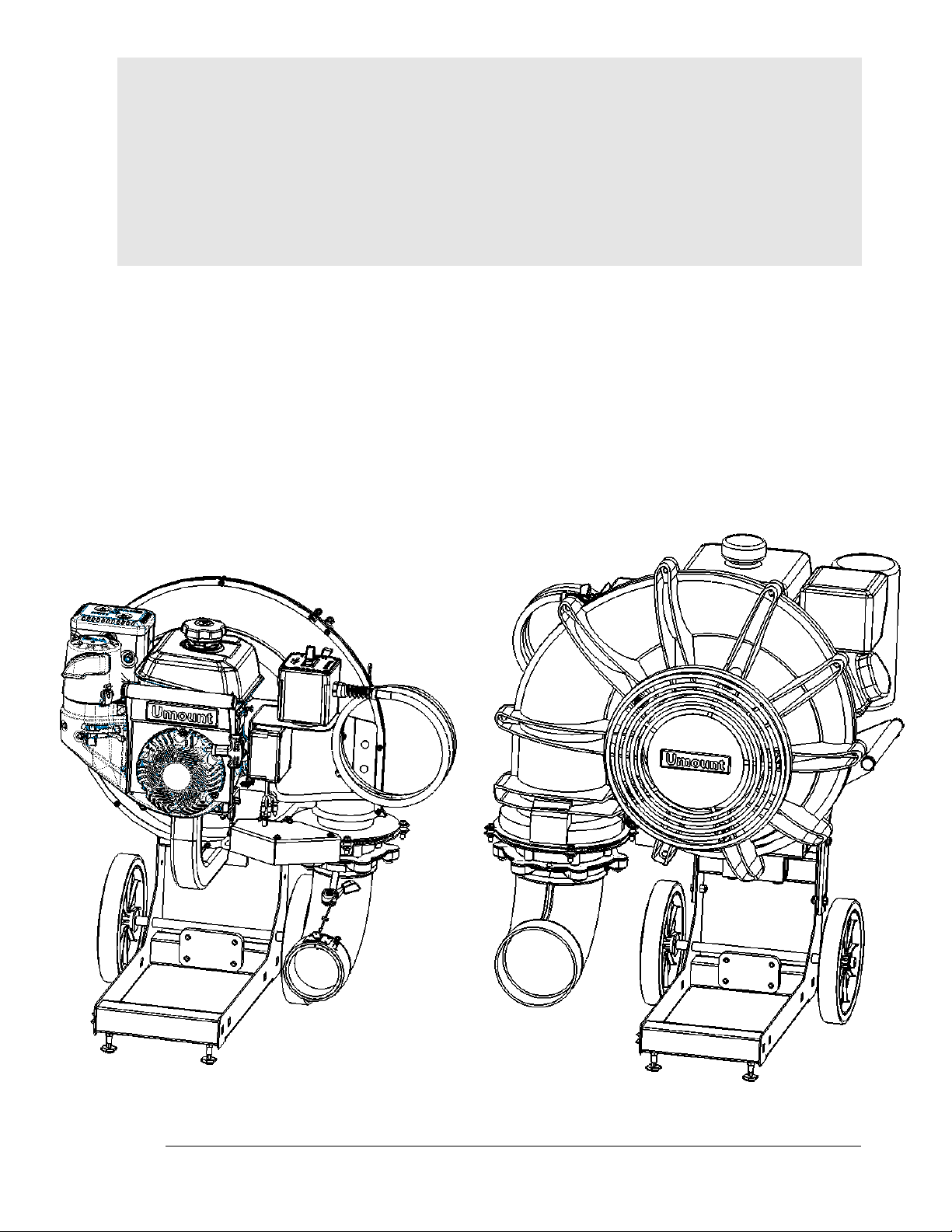
Umount 10018 User manual

Front Mount Blower
(12-2022) 1
Umount
Front Mount Blower
7hp and 14hp
Owner’s Manual

Front Mount Blower
(12-2022) 2
Umount
734 Washington Ave, Holland, MI 49423
E-mail: info@umountblowers.com
Website: www.umountblowers.com
Table of Contents
SPECIFICATIONS................................................................................3
SERIAL LABEL LOCATION..................................................................4
BLOWER OVERVIEW..........................................................................5
SAFETY ...............................................................................................6
CONTROL BOX FUNCTIONS..............................................................9
BLOWER ASSEMBLY –14hp Models................................................10
BLOWER ASSEMBLY –7hp Models..................................................11
NOZZLE ASSEMBLY –14hp Models.................................................12
NOZZLE ASSEMBLY –7hp Models...................................................13
HAND CONTROL BOX ASSEMBLY ..................................................14
FOOT CONTROL BOX ASSEMBLY...................................................15
CART ASSEMBLY..............................................................................16
CONTROL BOX MOUNT....................................................................17
VEHICLE MOUNTS............................................................................18
ACCESSORIES..................................................................................19
ELECTRICAL SCHEMATIC –7hp......................................................20

Front Mount Blower
(12-2022) 3
SPECIFICATIONS
Models
10018 (Hand Control 7hp)
10681 (Foot Control 7hp)
Models
10845 (Hand Control 14hp)
10867 (Foot Control 14hp)
Engine
Manufacturer
Kohler
Kohler
Model
CH270
CH440
Horse Power
7 hp
14 hp
CC’s
208cc
429cc
Electrical
10 amp
10 amp
Electric Start
No
Yes
Recoil Start
Yes
Yes
Run Time per Tank
~2.5 Hours
~2.5 Hours
Engine Warranty
3 Years
3 Years
FRAME
Frame Construction
Steel
Steel
Frame Coating
Powder/Zinc
Powder/Zinc
BLOWER
Housing Construction
Polyethylene
Polyethylene
Impeller Construction
Composite
Composite
Impeller Diameter
16” 16 Blade
18” 16 Blade
CFM
~2300
~4300
MPH
220
220
NOZZLE
Nozzle Construction
Flexible PVC
Flexible PVC
Discharge Outlet Diameter
4”
6.5”
Height Adjustment
2.5”
2.5”
Multi-Directional Rotation
210 Degrees
210 Degrees
Magnetic Break-Away System
Yes
Yes
CONTROL BOX
Control Box Construction
Polypropylene
Polypropylene
Hand Control Available
Yes
Yes
Hand Control Cable Length
6’
6’
Foot Control Available
Yes
Yes
Foot Control Cable Length
4’
4’
DIMENSIONS
Weight
90lbs
148lbs
Height
25”
31”
Length
20”
25”
Width
27”
30”

Front Mount Blower
(12-2022) 4
SERIAL LABEL LOCATION
Serial number label location (Located below engine)

Front Mount Blower
(12-2022) 5
**Hand Control
**Hand Control
**Foot Control
**Foot Control
BLOWER OVERVIEW
Blower Assembly
Nozzle Assembly
Cart Assembly
Control Assembly
**Includes handle
7hp Models
14hp Models

Front Mount Blower
(12-2022) 6
SAFETY
WARNING: Used in this manual, this symbol points out important safety instructions which, if
not followed, could endanger the personal safety and/or property of yourself and others. Read and
follow all instructions in this manual before attempting to operate this machine. Failure to comply
with these instructions may result in personal injury.
WARNING: Engine Exhaust, some of its constituents, and certain vehicle components contain
or emit chemicals known to State of California to cause cancer and birth defects or other
reproductive harm.
DANGER: This machine was built to be operated according to the rules for safe operation in
this manual. As with any type of power equipment, carelessness or error on the part of the operator
can result in serious injury. This machine is capable of amputating hands and feet and throwing
objects. Failure to observe the following safety instructions could result in serious injury or death.
DANGER:
•Do not operate on steep slopes. If vehicle can back up without the wheels slipping, reduce
speed and use extreme caution.
•Do not use on slopes greater than 15 degrees.
•Follow OSHA approved operation.
Engine Information
The engine manufacturer is responsible for all engine-related issues with regards to performance,
power-rating, specifications, warranty and service. Please refer to the engine manufacturer's
Owner's/Operator's Manual packed separately with your unit for more information.
General Operation
•Read this operator's manual carefully in its entirety before attempting to assemble this
machine. Read, understand, and follow all instructions on the machine and in the manual(s)
before operation. Be completely familiar with the controls and the proper use of the machine
before operating it. Keep this manual in a safe place for future and regular reference and for
ordering replacement parts.
•Your leaf blower is a powerful tool, not a plaything. Therefore, exercise extreme caution at
all times. Your unit has been designed to perform one job; to blow leaves, lawn clippings,
and debris. Do not use it for any other purpose.
•Always wear safety glasses or safety goggles during operation and while performing an
adjustment or repair, to protect eyes from debris or foreign objects that may be thrown from
machine.
•Wear close fitting slacks and shirt. Shirt and slacks that cover the arms and legs are
recommended. Do not wear loose fitting clothes or jewelry and secure hair so it is above
shoulder length. They can be caught in moving parts.
•Do not operate the unit while under the influence of alcohol or drugs.
•Never place your hands or any part of your body or clothing near rotating parts. Keep clear
of the discharge opening at all times. Never insert your hands, fingers, feet, or any other
part of your body or clothing into the discharge or air intake openings as the rotating impeller
inside the housing can cause serious injury.
•Never operate unit without directional discharge chute and plastic impeller housing properly
affixed to unit. These devices shield the operator from accidental contact with the rotating
impeller.
•Keep all guards and safety devices in place and operating properly.

Front Mount Blower
(12-2022) 7
•Exercise caution when operating blower. Do not allow the discharge to point in the direction
of bystanders or pets.
•If your machine should start making an unusual noise or vibration, immediately stop the
engine, disconnect the spark plug wire and move the wire away from the spark plug. Allow
the machine to stop and take the following steps:
oInspect for damage.
oRepair or replace any damaged parts.
oCheck for any loose parts and tighten to ensure continued safe operation.
•Muffler and engine become hot and can cause a burn. Do not touch.
•Do not allow leaves or other debris to build up on engine's muffler. The debris could ignite
and cause a fire.
•Do not operate engine if air cleaner or cover over carburetor air intake is removed, except
for adjustment. Removal of such parts could create a fire hazard.
•Only use accessories approved for this machine by the manufacturer. Read, understand,
and follow all instructions provided with the approved accessory.
•Only operate unit in good daylight. Do not operate unit at night or in dark areas where your
vision may be impaired.
•Keep the cooling system (blower housing area) clean to permit proper air circulation which
is essential to engine performance and life. Be certain to remove all grass, dirt, and
combustible debris from muffler area.
•If situations occur which are not covered by this manual, use care and good judgment.
Contact your dealer for assistance.
Service
•Use extreme care in handling gasoline and other fuels. They are extremely flammable and
the vapors are explosive.
•Store fuel and oil in approved containers, away from heat and open flame, and out of the
reach of children.
•Check and add fuel before starting the engine. Never remove gas cap or add fuel while the
engine is running. Allow engine to cool at least two minutes before refueling.
•Replace gasoline cap securely and wipe off any spilled gasoline before starting the engine
as it may cause a fire or explosion.
•Extinguish all cigarettes, cigars, pipes and other sources of ignition.
•Never refuel unit indoors because flammable vapors will accumulate in the area.
•Never store the machine or fuel container inside where there is an open flame or spark such
as a gas hot water heater, clothes dryer or furnace.
•Never run your machine in an enclosed area as the exhaust from the engine contains
carbon monoxide, which is an odorless, tasteless and deadly poisonous gas.
•To reduce fire hazard, keep engine and muffler free of leaves, grass, and other debris build-
up.
•Clean up fuel and oil spillage. Allow unit to cool at least 5 minutes before storing.
•Before cleaning, repairing, or inspecting, make certain the impeller and all moving parts
have stopped. Disconnect the spark plug wire and keep wire away from spark plug to
prevent accidental starting. Do not use flammable solutions to clean air filter.
•Keep all nuts, bolts, and screws tight to be sure the equipment is in safe working condition.
•Never tamper with safety devices. Check their proper operation regularly.
•Do not alter or tamper with the engine's governor setting. The governor controls the
maximum safe operating speed of the engine. Over speeding the engine is dangerous and
will cause damage to the engine and to other moving parts of the machine.
Gas And Oil Fill-Up
•Service the engine with gasoline and oil as instructed in the separate engine manual packed
with the blower. Read instructions carefully.
•WARNING: Use extreme care when handling gasoline. Gasoline is extremely
flammable and the vapors are explosive. Never fuel machine indoors or while the engine is
hot or running. Extinguish cigarettes, cigars, pipes, and other sources of ignition.

Front Mount Blower
(12-2022) 8
Stopping Engine
•To stop engine, depress OFF button until engine fully shuts off.
Starting Engine
•Check the engine oil. If necessary, add oil. See the engine owner’s manual for instructions.
•Move the choke lever on engine to CHOKE position. (A warm engine may not require
choking.)
•Move the throttle control to fast throttle position.
•(Recoil) Pull rope with a rapid, continuous, full arm stroke. Keeping a firm grip on the starter
handle, let the rope return to the starter slowly. Repeat until engine starts.
•(Electric Start Models) Insert the key into the ignition switch and turn it to start position
•When engine starts, move choke control gradually to RUN position.
MAINTAINING Your Leaf Blower
WARNING: Before performing any maintenance or repairs, stop the engine, wait until the
machine comes to a complete stop, disconnect the spark plug wire and ground against the engine to
prevent unintended starting.
Lubrication
•Engine: Follow the separate engine manual packed with your unit for lubrication instructions.
•Engine: Refer to the separate engine manual for all engine maintenance instructions.
Maintain engine oil as instructed in the separate engine manual packed with your unit.
•Service air cleaner every 25 hours under normal conditions. Poor engine performance and
flooding usually indicate that the air cleaner should be serviced. To service the air cleaner,
refer to the separate engine manual packed with your unit.
•The spark plug should be cleaned and the gap reset once a season. Spark plug
replacement is recommended at the start of each season. Clean the engine regularly with a
cloth or brush.
•Keep the cooling system (blower housing area) clean to permit proper air circulation which
is essential to engine performance and life. Be certain to remove all grass, dirt, and
combustible debris from muffler area.
Storing Your Leaf Blower
•Clean the equipment thoroughly.
•Wipe equipment with an oiled rag to prevent rust.
•Refer to engine manual for correct engine storage instructions.
•Store unit in a clean, dry area. Do not store next to corrosive materials such as fertilizer.
WARNING: Never store the machine or fuel container indoors where there is an open flame,
spark, or pilot light such as on a water heater, furnace, clothes dryer, or other gas appliance.

Front Mount Blower
(12-2022) 9
CONTROL BOX FUNCTIONS
1 –Nozzle Rotation
2 –Throttle
3 –Engine Stop Button
HAND
CONTROL
HAND
CONTROL
FOOT
CONTROL

Front Mount Blower
(12-2022) 10
BLOWER ASSEMBLY – 14hp Models
ITEM PART NO. QTY. DESCRIPTION
110850 1 WLDT, MOTOR MOUNT, LARGE SIZE
210024 1 MOUNT, CARRIER, FEMALE
310847 1 ENGINE, 14HP, KOHLER CH440 - 3275
410814 1 BLOWER, HOUSING, INLET, LARGE
510815 1 BLOWER, HOUSING, ENGINE MOUNT, LARGE
610818 2 PLATE, MOUNT, LARGE HOUSING
710821 1 WLDT, NOZZLE ADJUSTMENT, LARGE SIZE
810853 2 WLDT, HANDLE, ENGINE MOUNT
910824 1 IMPELLER, LARGE
10 10878 1 WLDT, AIR INTAKE, LARGE
11 10257 9 NUT, HEX, LCK, .25-20, NY, ZC
12 10258 15 SCREW, HEX, .25-20 X 1.75, ZC
13 10601 1 SWIVEL STOP, THROTTLE, W/ SCREW
14 10594 1 Screw, Pan, 8-32 x .25, ZC
15 10865 4 SCREW, HEX, PLASTIC THRD FRMING, 0.25-10 X 0.75" LG
16 10419 1 CABLE, .047D, 7.5L
17 10289 2 SWAGE, SLEEVE, HOUR GLASS, .046D WIRE, AL
18 10252 1 KNOB, 5 ARM, .38-16X1.0
19 10281 1 PIN, CLEVIS, .18D 1.0 USABLE, QUICK RELEASE
20 10266 3 SCREW, RND, 10-24 X .50, ZP
21 10420 9 TIE, CABLE, 4.0L
22 10862 1 WASHER, FLT, 0.453ID, 1.5OD, 0.50THCK

Front Mount Blower
(12-2022) 11
BLOWER ASSEMBLY – 7hp Models
ITEM PART NO. QTY. DESCRIPTION
110019 1 M OUNT W LDT, ENGINE
210024 1 M OUNT , CARRIER, FEM ALE
310029 1 BRACKET WLDT, ELBOW POSITION
410031 1 BRACKET WLDT, M OUNT, ACCESSORY
510243 1 HANDLE WLDT, BLOWER
610246 1 HANDLE WLDT, REAR
710249 1 ENGINE, GAS, 7HP
810250 1 HOUSING, FAN, M OTOR SIDE
910251 1 HOUSING, FAN, SIDE
10 10252 1 KNOB, 5 ARM , .38-16X1.0
11 10254 9 WASHER, .281B .625D 0.6T, SS
12 10257 4 NUT, HEX, LCK, .25-20, NY, ZC
13 10258 4 SCREW, HEX, .25-20 X 1.75, ZC
14 10259 1 IM PELLER ASSY, 16IN
15 10260 1 PLATE, MOUNT, HSNG, M OTOR
16 10261 1 SCREW, 08-16 X .75, HWH, PLASTITE
17 10266 5 SCREW, RND, 10-24 X .50, ZP
18 10267 2 CLAM P, LOOP, .25D
19 10268 1 CLAM P, LOOP, .50D
20 10270 4 SCREW, HEX, .31-24 X 1.00, GRADE 8, ZC
21 10272 4 SCREW, HEX, .31-18 X 1.5, ZP
22 10273 2 WASHER, FLT, 0.344B 0.69D 0.06T, ZP
23 10275 4 NUT, HEX, FLNG LCK, .31-18
24 10279 6 RIVET, BLIND, .19D, .251-.500 GRIP, ST, BLK
ITEM PART NO. QTY. DESCRIPTION
25 10280 6 WASHER, BACK-UP, .19 RIVET, .50D
26 10281 1 PIN, CLEVIS, .18D 1.0 USABLE, QUICK RELEASE
27 10288 6 SCREW, HEX, .31-9 X 1.0 LAG, ZP
28 10289 2 SWAGE, SLEEVE, HOUR GLASS, .046D WIRE, AL
29 10290 2 SCREW, TRS, 10-24 X .75, ZP
30 10291 9 NUT, HEX, LCK, 10-24, ZP
31 10294 1 BRACKET WLDT, M OUNT, ELECTRICAL CONTROL
32 10299 1 LABEL, UM OUNT
33 10361 1 STOP, CABLE
34 10376 7 SCREW, TRS, 10-24 X 1.25, ZP
35 10377 1 KEY, MACHINE, .18X.18X2.0L, ST
36 10419 1 CABLE, .047D, 7.5L
37 10509 1 WASHER, FLAT, .406B 1.25D .179T
38 10510 1 SCREW, HEX, .38-24X1.50, GR8, ZC
39 10569 2 SCREW, HEX, .31-18 X .75, GR5, ZP
40 10592 1 WASHER, LCK, SPLIT, .38B .68D .09T, ZC
41 10595 2 SCREW, TRS, WSR, 8 X .56, SHTM TL, ZC
42 10611 4 PLUG, RND, .88ID, SNAP-IN, BK
43 10736 1 PLATE, HOUSING, LIFT, SUPPORT
44 10645 1 SCREW, HEX, 0.25-20 X 0.63, ZC
45 10738 1 WASHER, LCK, SPLIT, 0.26B, 0.487OD, 0.062T, SS
46 10420 1 TIE, CABLE, 4.0L
47 10594 1 Screw, Pan, 8-32 x .25, ZC
48 10601 1 SWIVEL STOP, THROTTLE, W/ SCREW

Front Mount Blower
(12-2022) 12
NOZZLE ASSEMBLY – 14hp Models
ITEM PART NO. QTY. DESCRIPTION
110797 1 PLATE WLDT, ELBOW ADJUSTMENT, 6IN
210005 4 SPACER, .25B .50D .313T
310808 1 BRACKET, ELBOW MOTOR MOUNT, 6IN
410856 1 GEAR, NOZZLE ROTATION, 6IN, W INSERTS
510802 1 PLATE, MAGNET, 6IN
610804 1 PLATE, MOUNT, MAGNET, ELBOW, 6IN
710803 1 ELBOW, 6.0 DIA, 90DEG
810015 6 MAGNET, 1.0D .50T, NEODYNIUM
910256 12 SCREW, FH, 10-24 X .75, SS
10 10309 1 LABEL, WARNING, MAGNETIC
11 10254 4 WASHER, .281B .625D 0.6T, SS
12 10255 4 SCREW, HEX, .25-20 X 1.25, ZC
13 10719 1 MOTOR, GEAR, 12V, LH
14 10680 1 COVER, GEAR MOTOR, RH
15 10721 1 GEAR, PINION, DIA 32.0P 16T
16 10280 6 WASHER, BACK-UP, .19 RIVET, .50D
17 10368 3 STANDOFF, HEX, FEM, 10-32, .62L, ZP
18 10420 1 TIE, CABLE, 4.0L
19 10369 6 SCREW, HEX, LCK, 10-32X.38, ZP
20 10722 3 SCREW, M5X0.8 X 14.0, ZP
21 10745 1 TETHER, BREAK-AWAY NOZZLE
22 10879 1 CLAMP, SCREW, HOSE, 7.5"
23 10889 1
RETAINING RING, EXTERNAL, 0.395ID, 0.025
THCK
24 10894 1 FELT STRIP, 1/16" THCK, 1" WIDE
Aftermarket Assembly Part# 10896

Front Mount Blower
(12-2022) 13
NOZZLE ASSEMBLY – 7hp Models
ITEM PART NO. QTY. DESCRIPTION
110002 1 PLATE WLDT, ELBOW ADJUSTMENT
210005 4 SPACER, .25B .50D .313T
310720 1 BRACKET, ELBOW MOTOR MOUNT
410006 1 GEAR, NOZZLE ROTATION
510008 1 PLATE, MAGNET
610013 1 PLATE, MOUNT, MAGNET, ELBOW
710011 1 ELBOW, 4.0 DIA, 90DEG
810015 5 MAGNET, 1.0D .50T, NEODYNIUM
910353 1 BAND WLDT, CLAMP, ELBOW
10 10256 10 SCREW, FH, 10-24 X .75, SS
11 10309 1 LABEL, WARNING, MAGNETIC
12 10356 1 BRACKET WLDT, CABLE STOP, ELBOW
13 10362 4 SCREW, BINDING BARREL, 10-24X.31, SS
14 10359 1 CABLE, ADJUSTMENT, ELBOW
15 10361 1 STOP, CABLE
ITEM PART NO. QTY. DESCRIPTION
16 10352 1 KNARP, CABLE
17 10414 1 STRAP, SLEEVE, ELBOW
18 10254 4 WASHER, .281B .625D 0.6T, SS
19 10255 4 SCREW, HEX, .25-20 X 1.25, ZC
20 10719 1 MOTOR, GEAR, 12V, LH
21 10680 1 COVER, GEAR MOTOR, RH
22 10721 1 GEAR, PINION, DIA 32.0P 16T
23 10280 6 WASHER, BACK-UP, .19 RIVET, .50D
24 10368 3 STANDOFF, HEX, FEM, 10-32, .62L, ZP
25 10420 1 TIE, CABLE, 4.0L
26 10369 6 SCREW, HEX, LCK, 10-32X.38, ZP
27 10615 1 CONTROL, THROTTLE, RIGHT
28 10722 3 SCREW, M5X0.8 X 14.0, ZP
29 10745 1 TETHER, BREAK-AWAY NOZZLE
30 10889 1
RETAINING RING, EXTERNAL, 0.395ID, 0.025
THCK
Aftermarket Assembly Part# 10833

Front Mount Blower
(12-2022) 14
HAND CONTROL BOX ASSEMBLY
ITEM PART NO. QTY. DESCRIPTION
110254 1 WASHER, .281B .625D 0.6T, SS
210255 1 SCREW, HEX, .25-20 X 1.25, ZC
310257 2 NUT, HEX, LCK, .25-20, NY, ZC
410290 2 SCREW, TRS, 10-24 X .75, ZP
510291 2 NUT, HEX, LCK, 10-24, ZP
610308 1
LABEL, CONTROL BOX, THROTTLE, DIRECTION,
LOGO
710422 1 M AGNET, RND, 80LBS, 2.625D .38T
810506 1 STUD, 0.25D 2.0L, .25-20X.75L, SS
910507 1 NUT, HEX, .25-20, ZC
10 10535 1 THROTTLE, CABLE
11 10614 1 CONTROL, THROTTLE, LEFT
12 10619 85" CASING, THROTTLE CABLE
13 10620 1 ASSEM BLY, ELECTRICAL CONTROL BOX [PRE-ASM]
14 10626 2 CAP, THROTTLE CABLE
15 10296 1 SWITCH. TOGGLE
16 10536 1 SWITCH, M OM ENTARY
**Complete Assembly
PART NO.
DESCRIPTION
10537
HAND CONTROL ASSEMBLY 7HP
10537-14
HAND CONTROL ASSEMBLY 14HP

Front Mount Blower
(12-2022) 15
FOOT CONTROL BOX ASSEMBLY
**Complete Assembly
PART NO.
DESCRIPTION
10664
FOOT CONTROL ASSEMBLY 7HP
10664-14
FOOT CONTROL ASSEMBLY 14HP

Front Mount Blower
(12-2022) 16
CART ASSEMBLY
ITEM
PART NO.
QTY.
DESCRIPTION
1
10022
1
MOUNT, CARRIER, MALE
2
10042
1
CART WLDT
3
10043
2
WHEEL, 10.0D 1.25W
4
10046
2
LEVELER, .31-18 X 3.30 , STL THD, NYL BASE
5
10253
4
SCREW, FHSCS, .38-16 X 1.00, NL, BK
6
10264
2
CAP, PUSH RING, .63
7
10275
2
NUT, HEX, FLNG LCK, .31-18
*8
10869
1
HANDLE, CART
*9
10546
4
WASHER, FLAT, .406B .857D .05T
*10
10524
4
SCREW, HEX, .38-16 X 1.0
**Cart Included with all Blower Purchases
7HP BLOWER- CART ONLY
14HP BLOWER- CART W/ HANDLE
Aftermarket Cart Assembly Part# 10041
(Handle and Handle Hardware Sold Separately)

Front Mount Blower
(12-2022) 17
CONTROL BOX MOUNT
(Included Hand Control Blowers)
Aftermarket Control Box Mount (INCLUDES EVERYTHING BELOW) Part# 10350

Front Mount Blower
(12-2022) 18
VEHICLE MOUNTS
Features Umount Quick Attach System

Front Mount Blower
(12-2022) 19
ACCESSORIES
All work the Umount vehicle mounts Quick Attach system

Front Mount Blower
(12-2022) 20
ELECTRICAL SCHEMATIC – 7hp
This manual suits for next models
3
Table of contents