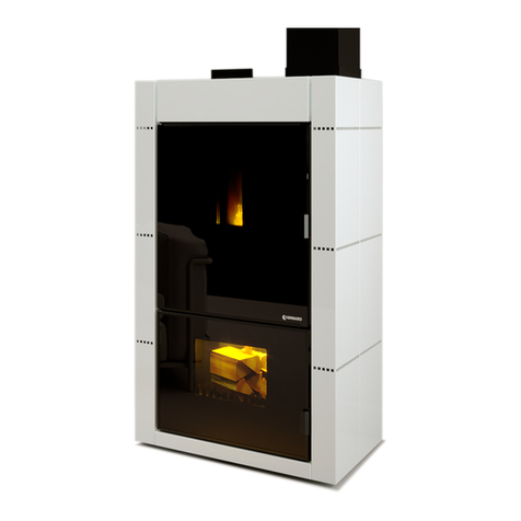
UNGARO Bico Fire User manual


Chapter 1
Chapter 2
Chapter 3
Chapter 4
Chapter5
Chapter 6
Chapter 7
Chapter 8
Chapter 9
Chapter 10
Charter 11
Chapter 12
Chapter 13
Chapter 14
2
5.1 Breakage Exhaust Fan
5.2 Breakage ot motor that refills pellets
5.3 Breakage ot Circulation Pump
5.4 Does not start
5.5 Lack ot electricity
5.6 Electrical Security
5.7 Security in releasing tumes
5.8 Pellets Temperature Security
5.9 Pressure System Satety
.Jnstal/atlon
5.1 Assembling
5.2 Smoke Release
5.3 Electric Connection
5.4 Air Comburent Pellet Wood
5.5 Dimension and Distant Security
6.1 Control Pad
6.2 Description Signs Remote Contral
6.3 Parameter Regulation
6.4 Turning oft Thermostove
pag. 3
pag. 9
pag. 9
pag. 9
pag. 9
pag. 9
pag. 9
pag. 10
pag. 10
pag. 10
pag. 11
pag. 11
pag. 11
pag. 11
pag. 11
pag. 12
Pil9, 15
pag. 15
pag. 16
pag. 17
pag. 18
System Diagram Closed Circuit
System Diagram Open Circuit
Electric Assembling Diagram
Connectors tor Electronic Card
Producters Certificate tor Bica Fire 20
Producers Certificate tor Bica Fire 35
Guarantee
pag. 35
pag. 39
pag. 42
pag. 43
pag. 44
pag. 45
pag. 46
pag. 47
pag. 49

MANUALE INSTALLATORE
Desëriptiol'l~'
u
TERMOSTUFE A PELLETS
The UNGARO Bico Fire Thermostoves, that work esclusively with pellets and wood, are equipped
with two separate combustion chambers, two separate smoke pipes and two heat exchanges in cop-
per, which permit the development of approx. a 90% return.
They are doted with an electronic card that permitsthe regulation of the temperature in the pellet area
as in the wood area. The Bico-Fire is equippedwith a Chronothermostat that makes possibile the
turning on and oft automatically which automates the running of the thermostove (the Chronothermo-
stat works on the pellet area of the stove). The Bico-Fire brings heat to the systems radiators with a
thermic potency that autoregulates its functioningaccording to area to be heated. It is sufticient to set
systems heatingwater temperature (60°c + 75°C)to get comfort desired.
The UNGARO Bico-Firealso produce hot air, thanks to a fan of approx. 60m3/hthat permits a convec-
tional heating of the area where thermostove is installed.
Thanks to an optional kit,they also produce continuoushot sanitary water in a healthyand secure way
without accumulation need.
The UNGARO Bico-Fireare equipped with sophisticatedsecurity devices that guarantee efficient and
practical use.
AII they need is the refilling with wood pellets and setthe functions according to personal needs.
3

4

".,"~'-'''*-'"''---
Figure 1
~-~,------ MANUALE INSTALLATORE
,"""-'-"'-"~"--'-~' -.-.,.,.,,,-~--
2
TechnicalOharacteristiês
uscita canna fumaria -peller
84
~-~:---4? - ----- --1
,... '- ---
,, <-- -
- -
r~f~~
l:'I" ]
:'\: l
i
: \, --- -
~-t~ -_. ".
1~ l~?-,~ I'~ 'd
>-'- --
~ ,u'c---, "' I~ :>. 28 I
N~: _n5;~L. ~ /'f, (' -
--
1-LJ~: ((1)\\ "S',h)) :'1-
-'%)) ~-)-' '-~' ,
IJ")
r-...
1 1-
,I
'-'- wico impianto manuale
/),Y' L. I
i..;lJ ?:--;';;~~;;;:;;ianto.utomarieo
0 0 0 0 ~--'
1
1
-~6:11 -~8,5.- - "l
,.5, .5 , a-
r-...
29
..
!
~
'----.
,.....---
-41
1-
IJ")
N
~
.:::::
........
-..
-
JJ---
......
=-
r-...
\.0
~
BICO-FIRE35
VI
tri'--
IJ")
inare"o ariacomburenteDellet
;--'
82 ---
5

Figura 2
6
'-4.
,-..
79
.-. .3915 "'1
,-...
useita vasoespansione aperto
seaneotermICO
r-" valvola3Bar
",:
IJ:):
Ni ,-
0'\
IJ
20 ~6/5~
.i11,5 I
~I.,. .,
",:
0\:
Lr) ,
!
'<t"
~,
l 1.-
-
-39
IJ")
0.1 ~\\Hi/~
~u
=~=
,-' r-
L
IJ")
IJ:)
,
~
BICO-FIRE20
useitacannafumaria.Ieona
lII
Lr)
M'
~:
,ellet
(arico im!!.ianto automatieo
ILr)
IJ:).0<
0.1'
'<t";
,... -_J_'..
.u,s -

MANUALE INSTALLATORE
~ -~_c~ --4- .. '''''''' --, ...
Génerall nstruction 3
Installation and maintenanceshould be done by qualified personnel only,in respect to existing laws
on the subject and accordingto company indications.
Before installing and maintenance of the product, it is necessary to read the included instructions
carefully.
These thermostoves must be used only for the purposes in which they are made for, therefore, re-
sponsibility for damages caused to persons, animals or things for improper use is to be retained at
the consumers expense.
The thermostove must be install,d by qualified personnelwhom will assume all responsibility
for instalment and properfunctioning of the product. Ungaro S.r.l. will not be responsible if
these precautions are not made.
Once product is unpacked,the consumer should make sure of the integrity and complete contents of
the product; if not, so the company should becontacted.
Before installation we suggest an accurate cleaning of all pipes in the system so that any residues,
that could interfere with correct functioning, may be removed.
In case the thermostove has not been in use for a long periodof time it is advisable:
.Place the general switch in the 0 position;
.Close the systemswater taps situated behindthe stove;
.If there is risk of freezing, empty the thermic and sanitary system.
The extraordinary maintenanceof the thermostove,which is on expense of the client, must be
scheduled at lease once a year,programming itwith the service technician.
Do not touch if barefootand/or any part of body iswet or damp;
It is forbidden to modifythe security or adjustmentdeviceswithout manufacturers indicationsor
Authorization;
Do not pull, unplug, or twist the elctric wires even if the stove is not connected to anelectrical outlet;
7

Avoid blocking windows doors etc. where installation is because a ventilated room is neces-
sar)' for a correct combustion.
It is obbligatory to connect externally thermic exhaust tubes and security valve.
Figure 3
UNGARO S.r.!. declines any responsibiliy in case of damage to persons or things for not ob-
serving this obbligation.
A correct installation of the smoke pipes is important, they must travel separately for a cor-
rect combustion.
The minimum sections to adopt are:
.Wood area 180 mmo
.Pellet area 80 mmo
8

-- - u- _u uu - --u u -uu
MANUALE INSTALLATORE
Security Devices', 4
4.1 Breakage of the exhaust fan
Incase of blockage of the exhaust fan, the thermostoves electronic card willautomatically block the
pellets, and an alarm system isvisualized on the display stopping everything automatically (no dep).
4.2 Breakage of motor that refills pellets
In case the motor that refills pellets stops because of a coclea block or because of breakage, the
following alarm will show: in case of breakage in working phase, it will continue working until it rea-
ches a minimum level of functioning giving oft alarm (pull brac )
4.3 Breakage of circulation pump
In case the circulation pump is blocked or burns out,the thermostove goes in alarm (sic oft and
Hot h20) and the pellet area stops automatically while the wood area will continue to work. The
thermic escape valve, by opening,will avoid that the stove will go over the 100°C and thanks to auto-
matic refilling group that cools oft the thermostove.
4.4 Thermostove does not turn ON
If during the turning on phase there is not an adequatef1amedevelopmentthe thermostove will show
on display 01 "ALARM"while on display 02 in an alternatineway
"PUL BRAC-NO FIRE".
THIS ALARM ISA REMINDERTHAT BEFORE THE STARTING PHASE BEGINS, MAKE SURE
THAT THE BRACIER (the piece where pellets are released and then burn and where ashes
collect infront ofstove) IS COMPLETELY FREEOF ASHES, CLEAN AND IN THE CORRECT
POSITION.
The thermostove goes in alarm and stops automatically. After the cooling oft of the stove you can
procede to the cleaning of the bracier and a new starting. In case of testing on the part of a service
technician, the successive chapterswill explain howto bypass the various alarms.
4.5 Lack (absence) of electricity
In case there is a short lack of electricity, the thermostove will automatically turn back on. In case
there is a longer lack of electricity, it may be possibile that a small amount of smoke escapes the
stove.
THERE IS ABSOLUTELY NO SECURITY RISK.
When electricity returns and the display Di shows "ALARM" while on D2 "NO RETE", after the coo-
ling oft of the stove the braciercan be cleaned and you can procede to a new starting.
4.6 Electrical security
In case of violent lightening and therefore problemswith electrical problems, the thermostove is pro-
tected by two fuses (2,5 A 250V), situated behind the stove under the wire, slide the cover and sub-
stitute.
9

4.7 Security in releasing fumes
Incasethepipingthatreleasesfumesisobstructed,thethermostovegoesinalarm(no dep) blocking
thefunctioning.
4.8 Safety in Pellet Tank temperature
Inthe rarestcasewherea hightemperatureisverifiedonthe insideof thepellettank,themanualre-
armofthesecuritythermostatgeneratesanalarm(hot pellet)interruptingthefunctioningofthestove
4.9 Pressure System Safety
The pressure system is controlled electronically and must be contained between 0.3 and 2 bar. If this
is not verified the thermostove goes in alarm and the display will show "ALARM PRESS". Verify the
system pressure:
that may be low or high.
By keeping the P2 pressed for a few seconds, the pressure state can be verified showing up on the
displayDI.
The securitv valve of the Thermostove does not allow the pressure to gOover the 3 bar. auto-
maticallv externallv releasing excess water.
10

MANUALE INSTALLATORE
'~''''''-,--'''''?_,_..'>
Installatioh "" 5
f~f ,;~
5.1 Assembling
The UNGARO Thermostoves must be installed by assistance centres and authorized personnelonly,
to whom this manual is destined.
5.2 Smoke Release
The smoke release system is based upon the depression (pulling) in the combustion chamberand a
light overpressure upon the smoke release (torced release). This makes it essential that the release
tube is correctly and hermeticallyinstalled, externally sealingthe connection ,to avoid the excaping
ot soot. This release can travel internallly or externallyot the abitation.
Installation of the smoke pipes:
5.3 Electric connection
In reterring to figure 8, measure and dril! holes in wall (0100 mm tor
the pellet area and 0185 mm tor the wood area), to insert the smoke
release tube, providing to install connecting T (Obbligatory) with
inspection caps, doted with chimney conducts (four winds), tor the
protection trom rain and wind. Do not position grills or other in the end
part ot the smoke pipe, that may compromise the exiting ot smoke,
and send stove in alarm (no dep, only in the pellet area).
For the keeping ot the tubes and their isolation, exclusively use mate-
riaIs that are heat resistent (up to 300°C) as alluminum tape, stone
wool, silicone tor hightemperatures.
PLEASE NOTE:
ALL PARTS OF SMOKE CONDUCT MUST BE INSPECTABLE AND
REMOVABLE TO MAKE POSSIBLE INTERNAL CLEANING.
The thermostove is providedwith an electric cable to be connected to a 230 V 50Hz + ground, obbli-
gatory as in 46/90 law. Avoid the cable coming into contactwith hot thermostove.
5.4 Air Combustion Pellet and Wood
It is obbliaatorv that air combustion be directlv taken externallv.
Every combustion phenomenon necessitates air (oxygen). Theretore, every thermostove extracts air
trom the area in which it is positionedand this air must be reintegrated.
A bad combustion may be provokedby scarse air circulation inside the habitation and this trequently
happens with new modern homes,which have hermeticwindows and doors.
The situation also becomes problematic when there are air currents on the inside ot the room. To a-
void this type ot problem we recommend the insertion ot a permanent air grill on a window or near the
thermostove.
-, ,--- ,-_.,----
1 1

Assembling aspiration pipa tor extarnal air obbliaatorv
In referring to figure 1 or 2, measure and drill a hole inwall 6,5 cm minimum diameter for the aspiration
tube air passage for the pellet area and a 10,5cm for thewood area.
Connect the thermostovewith the outside with steeltubes.
The conduct must endwith a 90° vertical curvethat faces the ground with wind protection (fig. 5).
- - -- J[Q]
LI5D J
u~
n\J
Figure 5
5.5 Dimension and Security Distances
The thermostove must be placed on a heat resistant flooring. If it is placed on an inflamable floar, it is
necessary for it to be placed on a non intlamabie surface.
The following table shows the dimensions of the extra surface and the relative security distances in
mmo
Figure 6
12

MANUALE INSTALLATORE
The thermostove is to be placed 50 that electric and plumbing attachments are easily accessibile.
It placed as in the tollowing figure, at least 20 cm trom walls is necessary:
~2.j
l==
- --- ----
- --------
~-----
-----
-----
Figure 7
It positioned as in tollowing figure, at least 10 cm trom walls is necessary:
--.-----_.-
--------
---- -
-
Figure 8
13
REFEREN- InfJamable0- Non-JnfJamable
CES bjects Obiects
A200 100
B 800 400
C200 100

14

MANUALE INSTALLATORE
---- -,-'. - .=""". --~-~. .- .- --
.$~rting the Thermo.!i~~v~\"t:.
',' . ,:,:1(.", ".'.
6.1 Control Pad
STEP 1.PreliminaryControlStarting Pellet
Before turning on the Thermostove verify that the pellet tank is refilled, that the air combustion
chamber is clean, and that the glass door is closed, that the switch is plugged into outlet and that
button behind the stove is in 1 position.
We recommend that damp pellets is not used and that the diameter is not over 6mm.
Control the pressure inthe stovekeeping the P2 key pressed,on display 01 wil! read "1.0b";
.0.
.e)
~*
Figure9
Thepressureis constantlymaintainedthanksto anautomaticloadingva\vepositionedonthe intemalleftside
ofthe thermostove.
STEP 2. Refilling of Circulator
After verifying the systems pressure start the circulator manually by pressing P1 and P2 contempo-
rarily for afew minutes, this way giving the circulator the possibility to tilI up with water, and in the
meantime freeing the system of air throughthe air vent valves positioned on the radiators.
STEP3. Releaseair circulator
Reachthe intemal partof the stove by removingtop andside panelor ceramic on right side.
Act upon the pump by unscrewing the air release screw in the back, permittingin this way
the fillingup with water and starting. Screw back on the screw and reposition the top of the
Thermostove and the side panel. Ifafter this operation the pump does not start, control the
tension (220 Volt) the relative bite,if present; control the electric continuity of the pump and
ifthe case substitute. Ifnot present substitute the electronic card.
STEP 4. Starting pellet area
Press P4 key for afew seconds until the thermostove starts, the display wil! show "FAN ASP", in this
phase the stove wil! execute a diagnosis (approx. 20 seconds)on the smoke extractor.
...- ..-.. ----....--...
15

Following this phase "LaAD WOOD" will show up on display where the .coclea loads the pellets and
the stove starts.
Figure 10
When the fume temperature is sufficiently high (41° C) the thermostove wil! go to the "FIRE ON" mo-
de (staying in this phase for a few minutes permitting the flame to stabilize).
Figure 11
At this point the 01 display will visualize the heating potency that must be set at value 9 (through
keys P5 and P6) for the first functioning hours, while on display 02 wil! be visualized the water tem-
perature that must be set at approx. 65°C (pressing once the "SET" key and increasing or decrea-
sing through keys P2 and P1).
STEP 5. Starting wood area
On the control pad, when only the wood area is to be turned on, the D1 display will visualize off and
the 02 will visualize the water temperature sent out. W
cl!7~
5<::J
,*,*
Figure 12
In the wood area the temperature is controlled by the electron ic card that regulates according to the
temperature set for the air comburent.
In proportionally closing the shutter of the air comburent with a planned offset from 0 to 20°.
The process of turning on the wood area is totally manual, therefore procede as with a classic fire-
place.
6.2 Sign descriptions of control board
Component description when active led corresponding to following figures:
16

MANUALE INSTALLATORE
Turns onwhen chronothermostat is active, to disactivate P3 (3"),
show "oW' instead of day 1-7 with P1,confirm with P4.
Turns on when starting sparkplug is abilitated.
Turns on when pellet refillingmotor is functioning.
Turns on when contact with supplementary room thermostat is clo-
sed or bites are bypassed.
Turns on when display receives remote control signa!.
Turns on when fume expulsionmotor is active.
Turns onwhen water circulationpump is functioning.
Turns on when bypass fan is functioning.
Turns on when thermostove is in heating mode.
Turns on inflashing way when sanitary water is in use, if remains on
even in heating mode it must be blocked with ut04 and then 9 with
P1 then confirming with set (P3).
6.3 Parameter Regulation
Through keys PS-P6the heating potency function is regulated, to be able to regulate the water tem-
perature press key P3 once on display D1 or with remote control with left keys,"Set H20" wil! show
flashing while the water temperature is visualized on D2 display, to regulatewater temperature press
key P1-P2.
r;;:-.., ",.~.4" r;;:-..,
,~~NGRRD~".~:~~~." ~.
Ç!J ~!":I~..e5~ .CDJE!J
I ~' ~. *..
Figure13
When a card is substituted for optimal parameter reasons or to improve combustion and functiona-
lity.
Access to the programming of the electroniccard following the directions below:
Press the P3 (set) for 3" until the parameter ut01 on D1 shows, press again 3 times P3 until ut04
shows above and 00 below.
With P1 go to parameter F1 (numbers to 99 and then letters in alphabetical order) confirm with P3
and modify parameters necessary. To exit from the programming and confirming work done press
P4.
Before modifying the general program contact UNGARO S.r.1.
17

6.4 Turning oH Thermostove pellet area
Ta turn oft pellet area of thermostove pressfor a few seconds key P4 until "OFF" is shown on display
D1.
~
Figure 14
The coclea will stop right away while the other components will be stopped by their respective thermo-
stats. The thermostove needs at least 20 minutes for total cooling.
Turning off Thermostove wood area
Ta turn oft the wood area, procedeas in a classic fireplace meaning take away embers manually being
careful not to burnoneself on the hot sides of the thermostove.
PLEASE NOTE:
The thermostove is doted with an automatism that permits the cleaning of the bracier in the
pellet area after a certain periodof time, when this verifies the flame is decreased automatically
and display wUI read "PUL FIRE", after a few minutes the thermostove wUI start to function
normally.
Figure 15
ATTENTION:
During the first two or three times that the stove is turned on it may give off a bad odour becau-
se of the hardening of the surfaces therefore is is recommended to air out the room several ti-
mes; it is also recommended to avoid permanence in the room for long periods of time.
18

MANUALE INSTALLATORE
Remote,Gontrol
,"'''M~;'''~ - ,
16
2- 5-
Figure16
With the remote it is possibile to regulate the water temperature, potency and turning on/off of the
Thermostove.
To turn on Thermostove press together key 1and key 6, the Thermostovewil! automatically go on.
Pressingkeys 1 and 2 the water temperature is regulated,while with keys 5 and 6 the heating po-
tency and functioning is regulated.
To turn off the Thermostove press together keys 1 and 6; on the display of the thermostove wil! ap-
pear "OFF".
To substitute the 12 volt battery, behind the remote, remove cover and substitute.
Figure 17
0_- 19

20
Table of contents
Other UNGARO Stove manuals
Popular Stove manuals by other brands

Defy
Defy 501 Compact owner's manual

Harman Stove Company
Harman Stove Company I Installation and operator's manual

LA CASTELLAMONTE
LA CASTELLAMONTE RNO 200 Instruction manual for installation, use and maintenance

FEUERHAND
FEUERHAND PYRON user manual

Zibro
Zibro ARABELLA installation manual

Dal Zotto
Dal Zotto MARTA IDRO 2.0 user manual