Unical HP OWER ONE 70 Use and care manual

User’s and Installer’s Manual
70 - 90 - 120 - 140 - 160
ONE

2
"This manual is a translation from the official italian language version. For reasons of environmental respect the Company will not provide the hard copy in the original language which
could be directly requested or downloaded from the Company website at any time. In case of any dispute, the original language manual will be the trusted one"
INDEX
1PURPOSE AND CONTENT OF THE MANUAL.................................................................................................................... 4
1.1 CONSERVATION OF THE MANUAL................................................................................................................................ 4
1.2 GRAPHIC SYMBOLS........................................................................................................................................................... 4
2SAFETY LAWS ........................................................................................................................................................................... 4
3PERMITTED USES..................................................................................................................................................................... 5
4GENERAL SAFETY GUIDELINES ......................................................................................................................................... 5
4.1 WORKERS’ HEALTH AND SAFETY................................................................................................................................. 5
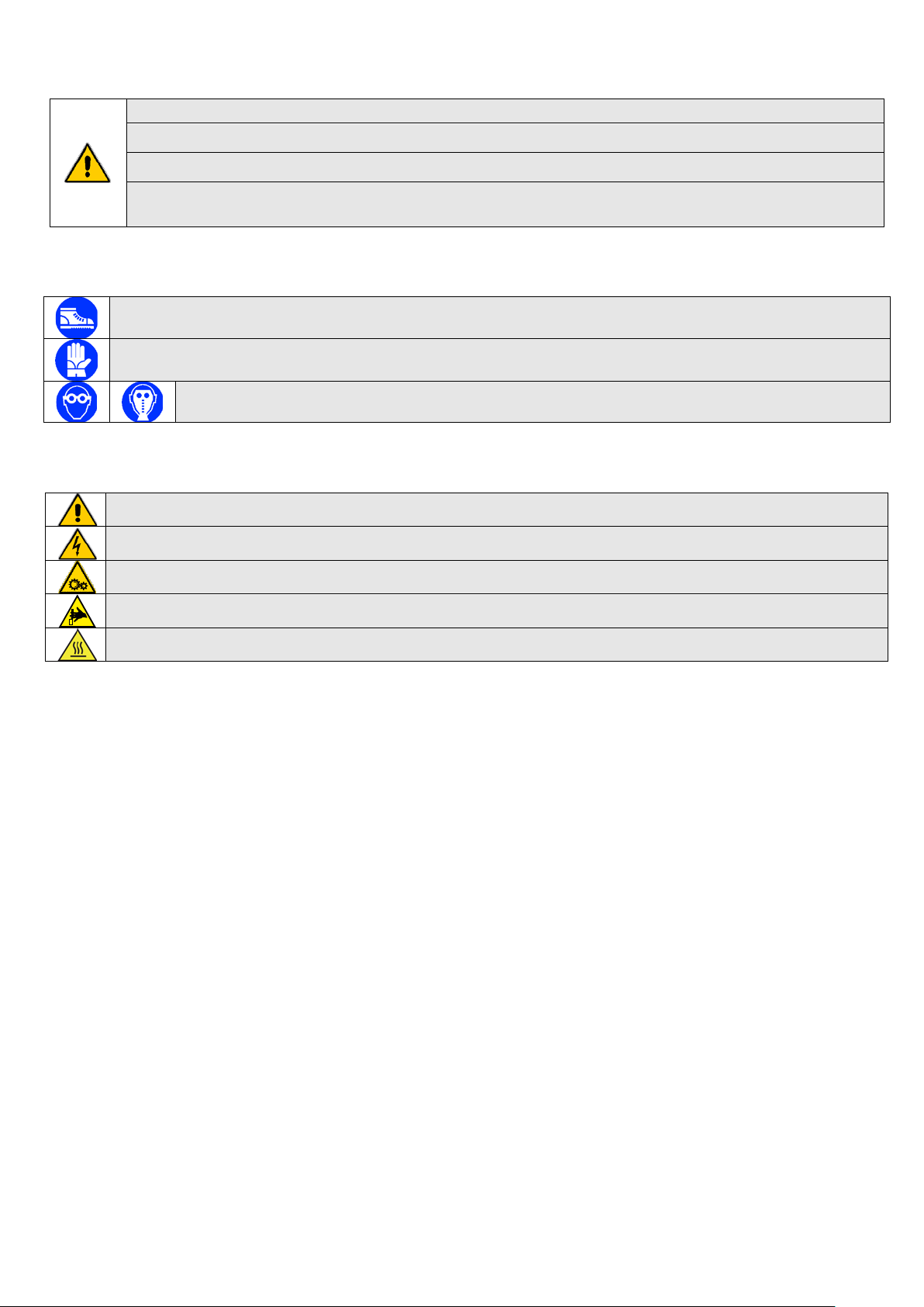
4.2 PERSONAL SAFETY EQUIPMENT.................................................................................................................................... 6
4.3 SAFETY SYMBOLS............................................................................................................................................................. 6
4.4 REFRIGERANT SAFETY DATA SHEET ........................................................................................................................... 7
5INSTALLATION......................................................................................................................................................................... 8
5.1 GENERALITY ...................................................................................................................................................................... 8
5.2 LIFTING AND HANDLING................................................................................................................................................. 8
5.3 LOCATION AND MINIMUM TECHNICAL CLEARANCES............................................................................................ 8
5.4 HYDRAULIC CONNECTIONS ........................................................................................................................................... 9
5.4.1 Characteristics of Water of the plant circuit.................................................................................................................. 9
5.4.2 Drainage connection.................................................................................................................................................... 10
5.4.3 Plant circuit charging .................................................................................................................................................. 10
5.4.4 Plant drainage system.................................................................................................................................................. 10
5.4.5 Hydraulic circuit .......................................................................................................................................................... 11
5.5 REFRIGERANT DIAGRAM OF HP_OWER ONE 70-90.................................................................................................. 11
5.6 REFRIGERANT DIAGRAM OF HP_OWER ONE 120 ..................................................................................................... 12
5.7 REFRIGERANTDIAGRAM OF HP_OWER ONE 140-160.............................................................................................. 12
5.8 ELECTRICAL CONNECTIONS ........................................................................................................................................ 12
5.8.1 Wiring terminal block................................................................................................................................................... 13
5.8.2 Terminal block and the electric box............................................................................................................................. 13
6START UP.................................................................................................................................................................................. 14
7INDICATIONS FOR THE USER ............................................................................................................................................ 14
8SHUTDOWNS FOR LONG PERIODS................................................................................................................................... 15
9MAINTENANCE AND PERIODICAL CONTROLS............................................................................................................ 15
9.1 CLEANING OF THE FINNED BATTERY ........................................................................................................................ 16
9.2 EXTRAORDINARY MAINTENANCE ............................................................................................................................. 16
9.3 ENVIRONMENTAL PROTECTION.................................................................................................................................. 16
10 DISPOSAL.............................................................................................................................................................................. 16
10.1 RESIDUAL RISKS.................................................................................................................................................................... 17
11 TECHNICAL DATA ............................................................................................................................................................. 18
12 PRODUCT FICHE (U.E.811/2013)...................................................................................................................................... 19
12.1 ELECTRIC DATA OF THE UNIT AND AUXILIARIES................................................................................................... 31
13 HYDRAULIC CIRCUIT AVAILABLE HEAD PRESSURE............................................................................................ 31
14 OPERATION LIMITS .......................................................................................................................................................... 34
14.1 EVAPORATOR WATER FLOW RATE............................................................................................................................. 34
14.2 COLD WATER TEMPERATURE (SUMMER OPERATION) .......................................................................................... 34
14.3 HOT WATER TEMPERATURE (WINTER OPERATION)............................................................................................... 34
14.4 AMBIENT AIR TEMPERATURE AND SUMMARIZING TABLES................................................................................ 34
15 CORRECTION FACTORS FOR USE OF GLYCOL........................................................................................................ 36
16 DIMENSIONS........................................................................................................................................................................ 36
16.1 MODELS HP_OWER ONE 70-90....................................................................................................................................... 36

3
16.2 MODELS HP_OWER ON 120 ............................................................................................................................................ 36
16.3 MODELS HP_OWER ONE 140-160................................................................................................................................... 37
16.4 ACCESS PROCEDURE TO THE INTERNAL PARTS OF THE UNIT............................................................................. 38
16.4.1 Mod. HP_OWER ONE 70-90....................................................................................................................................... 38
16.4.2 Mod. HP_OWER ONE 120 .......................................................................................................................................... 38
16.4.3 Mod. HP_OWER ONE 140-160................................................................................................................................... 39
17 REGISTER OF OPERATIONS OF MAINTENANCE ..................................................................................................... 40

4
The manual of HP_OWER ONE units collects all the necessary information for the better use of the equipment under safety
conditions for the operator thus meeting the requirements listed in the 2006/42/CE Equipment Directive and following
amendments.
1PURPOSE AND CONTENT OF THE MANUAL
This manual provides basic information as for the installation, the operation and the maintenance of heat pumps . It is addressed
to machine operators and it enables them to use the equipment efficiently, even if they do not have any previous specific
knowledge of it.
WARNING: Although this manual is also destined for the end-user utilizations, some discibed activities are allowed
only for trained technical personnels who should be in possession of Vocational and Technical Training allowing
them to be responsible for carrying out the activity. They should be properly updated with courses approved by the
competent authorities. These activities includ: installation, both ordinary and extraordinary maintenance,
appliance disposal and any other activity required by "qualified staff."
After the end of installation and/or maintenance of the appliance, the qualified operator has a duty to properly
inform the end-user about the use of the appliance and the necessary periodical checks.
The installer is responsible to deliver all necessary documentation (including this manual) to the user and should
ensure him to keep it in a safe place near the appliance where it can be available at any time.
This manual describes the characteristics of the equipment at the time in which it is being put on the market; therefore, it may not
include technological improvements introduced later by the company as part of its constant endeavour to enhance the
performance, ergonomics, safety and functionality of its products.
The company, therefore, is not constrained to update the manuals for previous versions of machines.
It’s recommended that, the user must follow the instructions contained in this booklet, especially those concerning the safety and
routine maintenance.
1.1 CONSERVATION OF THE MANUAL
The manual has to be always kept by the user for future reference. It has to be stored in a safe place, away from dusts and
moisture. It has to be available and accessible to all users who shall consult it when they are in doubt on how to operate the
equipment.
The company reserves the right to modify its products and related manuals without necessarily updating previous versions of the
reference material. It declines also any responsibility for possible inaccuracies in the manual if due to printing or transcription
errors.
The customer shall store any updated copy of the manual or parts of it delivered by the manufacturer as an attachment to this
manual.
The company is available to give any detailed information about this manual and to give information regarding the use and the
maintenance of its own units.
1.2 GRAPHIC SYMBOLS
Indicates operations that can be dangerous for people and/or disrupts the correct operation of the equipment.
Indicates prohibited operations.
Indicates important information that the operator has to follow in order to guarantee the correct operation of the
equipment in complete safety.
2SAFETY LAWS
The V4 units have been designed in compliance with the following Directives and Harmonised Norms concerning the safety of the
appliances:
•97/23/CE, 2014/35/UE, 2014/30/UE, 2011/65/UE, 2012/19/UE Community Directives.
•UNI EN 378-1, 378-2, UNI EN 12735-1 Norms.
•CEI EN 60335-2-40 Norms.
•CEI EN 55014-1, CEI EN 55014-2, CEI EN 61000-3-2, CEI EN 61000-3-3, CEI EN 62233 Norms.
And the following directives and regulations concerning the energy labeling and the eco-friendly products:
•Community directive 2009/125/CE and subsequent transpositions.
•Community directive 2010/30/UE and subsequent transpositions.
•Regulation UE No 811/2013.
•Regulation UE No 813/2013.

5
3PERMITTED USES
•The company excludes any contractual and extra contractual liabilities for damages caused to persons, animals or objects, by
incorrect installation, setting and maintenance, improper use of the equipment, and the partial or superficial reading of the
information contained in this manual.
•These units have been designed only for heating and/or cooling water. Any other use not expressly authorized by the
manufacturer is considered improper and therefore not allowed.
•The location of the plant, the hydraulic and electrical circuits must be established by the planting designer and must take into
account both technical requirements as well as any applicable local laws and authorized specifications.
•The execution of all works must be performed by skilled and qualified personnel, competent in the existing rules in different
countries.
4GENERAL SAFETY GUIDELINES
Before beginning to operate on units every user has to be perfectly knowledgeable about the functions of the equipment and its
controls and has to have read and understood the information listed in this manual.
It’s strictly forbidden to remove and/or tamper with any safety device.
Children or unassisted disabled persons are not allowed to use the appliance.
Do not touch the appliance when barefoot or parts of the body are wet or damp.
Do not clean the unit when the power is ‘ON’.
Do not pull, remove or twist the electrical cables coming out from the unit, even if it is disconnected from the main
power supply.
Do not step with your feet on the appliance, sit down and/or place any type of object.
Do not spray or pour water directly on the unit.
Do not dispose of, abandon or leave within reach of children packaging materials (cardboard, staples, plastic bags,
etc.) as they may represent a hazard.
Any routine or not-routine maintenance operation shall be carried out when the equipment has been shut down,
disconnected from electric power sources.
Do not put neither your hands nor insert screwdrivers, spanners or other tools into moving parts of the equipment.
The equipment supervisor and the maintenance man have to receive suitable training for the performance of their
tasks in safety.
Operators have to know how to use personal protective devices and have to know the accident-prevention guidelines
contained in national and international laws and norms.
4.1 WORKERS’ HEALTH AND SAFETY
The European Community has adopted a number of directives on workplace’s health and safety, which are 89/391/CEE,
89/686/CEE, 2009/104/CE, 86/188/CEE and 77/576/CEE directives, and the subsequent integrations/modification. Every employer
shall implement such provisions and ensure that their workers to respect them. We observe therefore that:
Do not tamper with or replace parts of the equipment without the specific consent of the manufacturer. The
manufacturer shall have no responsibility whatsoever in case of unauthorised operations.
Using components, expendable materials or spare parts that do not correspond to those recommended by the
manufacturer and/or listed in this manual may be dangerous for the operators and/or damage the equipment
The operator’s workplace has to be kept clean, tidy and free from objects that may prevent free movements.
Appropriate lighting of the work place shall be provided so as to allow the operator to carry out the required
operations safely. Poor or too strong lighting can cause risks.
Ensure that work places are always adequately ventilated and that aspirators are working, in good condition and in
compliance with the requirements of the laws in force.
The unit operates with R410A refrigerant gas, which is a greenhouse gas according to the F-gas Regulation (EU) 517/2014
(mandatory in the European area). This Regulation, among the provisions, requires all operators intervening in greenhouse gas
systems to be in possession of a certificate issued or recognized by the competent authority, attesting to a successful completion
of an examination entitling them to carry out such work. In particular:
Device contains up to 3kg of the total amount of refrigerant gas: Category II certificate.
Device contains 3kg or more than 3kg of the total amount of refrigerant gas: Category I certificate.
The refrigerant R410A in gaseous form is heavier than air and tends to concentrate highly in little ventilated environments when a
leak occurs. Its inhalation can cause dizziness, suffocation and can develop lethal gas if it becomes in contact with open flames or
hot objects, (please see “REFRIGERANT SAFETY DATA SHEET” paragraph 4.4).

6
For any intervention on the heat pump:
Wear appropriate Personal Protective Equipment (PPE) specifically, gloves and goggles.
Ensure that the workplace is well ventilated. Do not work in closed rooms or ditches with weak air circulation.
Do not work on the refrigerant near open flames or near hot parts.
Avoid any refrigera
nt leakage into the environment and pay particular attention to leakage from pipes and/or
fittings after evacuating the refrigerant circuit.
4.2 PERSONAL SAFETY EQUIPMENT
When operating and maintaining the V4 units, it is required to use the following personal protective equipment.
Protective clothing: Maintenance men and operators have to wear protective clothing that complies with the basic
safety requirements currently in force. In case of slippery floors, users have to wear safety shoes with non-slip soles.
Gloves: During maintenance or cleaning operation protection gloves have to be used
Mask and goggles: Respiratory protection (mask) and eye protection (goggles) should be used during
cleaning and maintenance operations.
4.3 SAFETY SYMBOLS
The unit features the following safety signs, which has to be complied with:
General hazards
Electric shock hazard
Presence of moving organs
Presence of surfaces that may cause injures
Presence of hot surfaces that can cause burns

7
4.4 REFRIGERANT SAFETY DATA SHEET
Name:
R410A (50% Difluoromethane (R32); 50% Pentafluoroethane (R125).
RISKS INDICATIONS
Major risks:
Asphyxia
Specific risks:
The rapid evaporation may cause freezing.
FIRST AID
General information:
Never give anything by mouth to an unconscious person.
Inhalation:
Move to fresh air.
Oxygen or artificial respiration if necessary.
Do not administer adrenaline or similar drugs.
Eyes contact:
Rinse carefully with water for at least 15 minutes and consult a doctor.
Contact with skin:
Wash immediately with plenty of water.
Take off immediately the contaminated clothing.
FIRE PREVENTION
Extinguishing Media:
Whatever.
Specific risks:
Increase in pressure.
Specific methods:
Use water spray to cool containers
ACCIDENTAL RELEASE ACTIONS
Personal precautions:
Evacuate personnel to safe areas.
Provide adequate ventilation.
Use personal protective equipment.
Environmental precautions:
Evaporate.
Cleaning method:
Evaporate.
HANDLING AND STORAGE
Manipulation
Action/technical precautions:
Provide sufficient air exchange and/or suction in work places.
Recommendations for safe use:
Do not breathe vapors or aerosol.
Storage:
Close tightly and store in a cool, dry and well ventilated place.
Store in original container. Incompatible products: explosive, flammable materials, Organic peroxide
EXPOSURE CONTROL / PERSONAL PROTECTION
Control parameters:
AEL (8-h e 12-h TWA) = 1000ml/m³ for each of the two components.
Respiratory protection:
For rescue and maintenance operation in storage tanks use self-contained respirator apparatus.
The vapors are heavier than air and can cause suffocation by reducing oxygen available for breathing.
Eyes protection:
Safety glasses.
Protection of hands:
Rubber gloves.
Hygiene measures:
Do not smoke.
PHYSICAL AND CHEMICAL PROPERTIES
Colour:
Colourless.
Odor:
Light.
Boiling point:
-52.8°C at atmospheric pressure.
Lighting point:
It does not ignite.
Density:
1.08kg/l at 25°C.
Solubility in water:
Negligible.
STABILITY AND REACTIVITY
Stability:
No reactivity when used with the appropriate instructions.
Materials to avoid:
Highly oxidizing materials. Incompatible with magnesium, zinc, sodium, potassium and aluminum.
The incompatibility is more serious if the metal is present in powdered form or if the surfaces were, recently,
unprotected.
Decomposition products
These products are halogenated compounds, hydrogen fluoride, carbon oxides (CO, CO2), carbonyl halides.
Risks:
TOXICOLOGICAL INFORMATION
Acute toxicity:
(R32) LC50/ inhalation /4 hours/on rat >760 ml/l.
(R125) LC50/ inhalation /4 hours/on rat >3480 mg/l.
Local effects:
Concentrations substantially above the TLV may cause narcotic effects.
Inhalation of decomposed products of high concentrations may cause respiratory failure (pulmonary edema).
Long term toxicity:
Did not show carcinogenic, teratogenic or mutagenic effects in animal experiments.
ECOLOGICAL INFORMATION
Global Warming Potential
2088
GWP (R744=1)
Ozone Depletion Potential
0
ODP (R11=1):
Disposal considerations:
usable with reconditioning.

8
5INSTALLATION
WARNING: All the operation described in next chapters MUST BE DONE BY TRAINED PEOPLE ONLY. Before any
operation on the unit, be sure that the electric supply is disconnected. Be sure also, using suitable obstructions,
that can avoid accidental power supply switching ON until the end of all operations.
5.1 GENERALITY
When installing or servicing the unit, it is necessary to strictly follow the rules listed in this manual, to conform to all the
specifications of the labels on the unit, and to take any possible precautions. Not observing the rules reported on this manual can
create dangerous situations.
After receiving the unit, immediately check its integrity. The unit left the factory in perfect condition; any eventual
damage has to be questioned to the carrier and recorded on the Delivery Note before signing it.
The company has to be informed, within 8 days, of the extent of the damage. The Customer should prepare a written statement of
any severe damage.
WARNING: The units are designed for outdoor installation. The place of installation must be entirely far away from
fire risk. All the necessary measures should be adopted in order to prevent the fire risk in the place of installation. The
outdoor ambient temperature shall not exceed 46°C. Above this value, the unit is no longer covered by the directives
in force in the area of pressure equipment.
WARNING: The unit should be installed so that adequate clearance is available for maintenance and repairation. The
warranty does not cover costs related to platforms or handling equipment necessary for any maintenance.
All maintenance and testing operations should be carried out only by QUALIFIED PERSONNEL.
Before any operation on the unit, make sure the power supply is disconnected.
WARNING: MOVING PARTS, RISK OF DEATH.
Disconnect the power supply and ensure that the fan is stopped before opening the front panel.
The temperatures of heads and discharge piping of the compressor are usually high.
Be careful when working near condensing coils.
The aluminum fins are very sharp and can cause serious injuries.
After the maintenance operations, close the panels tightly with the fastening screws.
5.2 LIFTING AND HANDLING
When unloading and installing the unit, it is highly recommended to
avoid any sudden move in order to protect the inner components.
Units can be lifted by means of a forklift or, in alternative, of belts,
b
eing sure not to damage the lateral panels and the cover. It is
important to keep the unit horizontal during these operations.
5.3 LOCATION AND MINIMUM TECHNICAL CLEARANCES
The all HP_OWER ONE units are designed for outdoor installation: any cover over the unit and location near trees (even if they
partially cover the unit) has to be avoided in order to prevent air recirculation. It is advisable to create a proper basement, with a
size similar to unit foot-print. Unit vibration level is very low: it is advisable however, to fit a rigid rubber band between basement
and unit base-frame. It is also possible to install anti-vibration supports (springs or rubbers) to keep vibrations at a very low level.
Absolute care has to be taken to ensure adequate air volume to the condenser. Re-circulation of discharge air has to be avoided;
failure to observe this point will result in poor performance or activation of safety controls. For these reasons it is absolutely
necessary to respect the following clearances:
MOD.
A
B
C
D
E
V4 06 HP_OWER ONE
70
1500 500 400 400 500
V4 08 HP_OWER ONE
90
1500 500 400 400 500
V4 12 HP_OWER ONE
120
1500 500 400 400 500

9
V4 14 e 14T HP_OWER
ONE 140
1500 500 400 400 500
V4 16 e 16T HP_OWER
ONE 160
1500 500 400 400 500
CAUTION:It is obligatory to install the unit on a firm and appropriate basement to support its weight. Considering
the weight of the unit, possible vibrations and resultant noise, we do not recommend suspension installion of the
unit; in this case, the firm is not responsible for any damage or inconvenience that may result.
5.4 HYDRAULIC CONNECTIONS
The hydraulic connections have to be installed in accordance with national and local regulations; pipes can be made up of steel,
galvanized steel or PVC. Pipes have to be designed depending on the nominal water flow and on the hydraulic pressure drops of
the system. All pipes have to be insulated with closed-cell material of adequate thickness. Chillers have to be connected to piping
by means of flexible joints. Piping should include:
•Hole thermometers to monitor the system’s temperature.
•Manual gate valves to separate the chiller from the hydraulic circuit.
•Y-shaped metallic filter and a dirt separator (to be mounted on the inlet pipe) with a mesh not larger than 1mm.
•Charging group and discharge valve, where necessary.
WARNING: Make sure that, when designing the pipe length and diameter, do not exceed the maximum head loss
on the plant side, please see the technical data given in the table of Paragraph 12 (available pressure head).
WARNING: Connect the pipes to the attacks by using always key against key system.
WARNING: The expansion vessel have a limited volume. The installator have to provide a further expansion vessel
if it is necessary.
WARNING: Unit water inlet pipe have to be in correspondence with the connection labelled: ”WATER INLET”,
otherwise the evaporator may freeze.
WARNING: It is compulsory to install on the WATER INLET connection a metallic filter (with a mesh not larger than
1mm) and a dirt separator. the warranty will no longer be valid If the water flow switch was manipulated or
altered or if the metallic filter and/or dirt separator were not installed. The filter and the dirt separator have to be
kept clean, therefore make sure that are clean after the unit installing the unit, and then check them periodically.
All units are standard supplied with the water flow switch (factory installed). The warranty will be invalidated if the
water flow switch was altered, removed, or if the water filter and the dirt separator were not installed on the unit.
Please refer to the wiring diagram for the water flow switch electric connections.
Make sur that the heating system and the safety valves must comply with the requirements of EN 12828.
5.4.1 Characteristics of Water of the plant circuit
To ensure the correct operation of the unit, the water should be adequately filtred (see what is reported at the beginning of this
paragraph) and that the amounts of dissolved substances should minimal. The maximum permitted values are given here below.
MAXIMUM PHYSICAL AND CHEMICAL CHARACTERISTICS ALLOWED BY THE WATER OF THE PLANT CIRCUIT
PH
7,5 - 9
Electrical conductivity
100 - 500 μS/cm
Total hardness
4,5 – 8,5 dH
Temperature
˂ 65°C
Oxygen content
˂ 0,1 ppm
Maximum glycol content
50 %
Phosphates (PO4)
˂ 2ppm
Manganese (Mn)
< 0,05 ppm

10
Iron (Fe)
< 0,3 ppm
Alkalinity (HCO3)
70 – 300 ppm
Chloride ions (Cl-)
< 50 ppm
sulfate ions (SO4)
< 50 ppm
Sulfide ion (S)
None
Ammonium ions (NH4)
None
Silica (SiO2)
< 30 ppm
5.4.2 Drainage connection
All the units of series have been designed to use their own base as a drain pan; a plastic pipe fitting is standard provided to be
installed onto the lower part of the unit in the special housing enabling the connection of a drainage pipe.
Each unit is also provided, on the basement of the hydronic kit (at the heat exchanger side), with a hole that can allow to drain any
condensed water can leach from plumbing pipes. As the pipes must be well-insulated, the production of condensed water is
however very low and therefore the connection of a drainage pipe to that hole is not very required.
5.4.3 Plant circuit charging
WARNING: Verify all the charging/topping up operations.
WARNING: Before beginning the charging/topping up operation of the plant circuit, disconnect the unit for the
electric power supply.
WARNING: The charging/topping up of the plant circuit must always be done under controlled conditions of
pressure (max 1 bar). Make sure that you have installed on the line of charging/topping up a pressure
reducerdevice and a relief valve.
WARNING: The water on the charging/topping up pipe must be suitably pre-filtered from any impurities and
suspended particles. Make sure that you have installed a cartridge filter removable. Make sure that an extractable
cartridge filter and a dirt separator have been installed.
WARNING: It is required to proceed by air purging periodically in order to eliminate the accumulated air in the
plant circuit system.
WARNING: Make sure to install an automatic air vent valve at the highest point of the system.
5.4.4 Plant drainage system
When it is necessary to drain the plant, close at first the inlet and outlet manual gate valves (not supplied) and then remove the
pipes that are disposed externally on the water inlet and on the water outlet in order to spill away the liquid contained in the unit
Drainage pipe fitting
Drainage pipe fitting housing
Drainage pipe fitting connected to the unit
During loading / reintegration operations, the vent valve cap must be partially
unscrewed to allow air to flow freely outside the valve.
(1) breather valve cap
ATTENTION. The air vent is a manual valve. Periodically it is necessary to perform
the air purge operations that accumulate in the system as just described.
You can use the service valve, when it is necessary to refill the plant or adapt the
concentration of glycol. Unscrew the cap of the service valve and connect to the
hose a pipe of 14 mm or (inner diameter size - check the faucet model that is
installed on your own unit
) connected to the water network, and then load the
system by unscrewing the knurled nut. When the operation is concluded, retighten
the knurled nut and screw on the cap. In any case, we recommend you to use for
the water loading of the plant an external tap whose arrangement is by the
installer.
Cap with gasket
Knurled nut
1
1

11
(for easier operation, it is recommended to install externally two draining valves, on the water inlet and on the water outlet,
between the unit and the manual gate valves).
5.4.5 Hydraulic circuit
Models: HP_OWER ONE 70-90
Models: HP_OWER ONE 120
A
B
HF
G
ED
C
A
B
HF
G
ED
C
HP_OWER ONE 140-160
A
B
H
F
G
E
D
C
KEY
A
Plate heat exchanger
E
Expansion vessel
B
Flow switch
F
Manual air vent valve
C
Service valve
G
Safety valve
D
High efficiency circulating pump with
H
Pressure gauge
5.5 REFRIGERANT DIAGRAM OF HP_OWER ONE 70-90
IN OUT
DT
ST
LP HP
4WV
LR EEV
FL FL
C
CLS
Pr
PV
PV
MF
SE
M
P
C
COMPRESSOR
CLS
COMPRESSOR LIQUID SEPARATOR
ST
COMPRESSOR INLET TEMPERATURE
DT
COMPRESSOR OUTLET TEMPERATURE
HP
HIGH PRESSURE TRANSDUCER
Pr
HIGH PRESSURE FLOW SWITCH
LP
LOW PRESSURE TRANSDUCER
4WV
INVERTING CYCLE VALVE
LR
LIQUID RECEIVER
EEV
ELECTRONIC EXPANSION VALVE
FL
FILTER
M
AXIAL FAN
MF
MUFFLER SILENCER
SE
OUTDOOR AIR TEMPERATURE
P
CIRCULATOR ON BOARD UNIT
IN
WATER INLET TEMPERATURE
OUT
WATER OUTLET TEMPERATURE

12
5.6 REFRIGERANT DIAGRAM OF HP_OWER ONE 120
IN OUT
DT
OS
ST
LP HP
4WV
LR EEV
FL FL
FL
C
CLS
PrPr
PV
PV
CP
CP SE
M
P
C
COMPRESSOR
CLS
COMPRESSOR LIQUID SEPARATOR
OS
OIL SEPARATOR
ST
COMPRESSOR INLET TEMPERATURE
DT
COMPRESSOR OUTLET TEMPERATURE
HP
HIGH PRESSURE TRANSDUCER
Pr
HIGH PRESSURE FLOW SWITCH
LP
LOW PRESSURE TRANSDUCER
4WV
INVERTING CYCLE VALVE
LR
LIQUID RECEIVER
EEV
ELECTRONIC EXPANSION VALVE
FL
FILTER
M
AXIAL FAN
SE
OUTDOOR AIR TEMPERATURE
P
CIRCULATOR ON BOARD UNIT
IN
WATER INLET TEMPERATURE
OUT
WATER OUTLET TEMPERATURE
CP
CAPILLARY
5.7 REFRIGERANT DIAGRAM OF HP_OWER ONE 140-160
IN OUT
DT
OS
ST
LP HP
4WV
LR EEV
FL FL
FL
C
CLS
Pr
PV Pr
PV
CP
SE
M
M
P
C
COMPRESSOR
CLS
COMPRESSOR LIQUID SEPARATOR
OS
OIL SEPARATOR
ST
COMPRESSOR INLET TEMPERATURE
DT
COMPRESSOR OUTLET TEMPERATURE
HP
HIGH PRESSURE TRANSDUCER
Pr
HIGH PRESSURE FLOW SWITCH
LP
LOW PRESSURE TRANSDUCER
4WV
INVERTING CYCLE VALVE
LR
LIQUID RECEIVER
EEV
ELECTRONIC EXPANSION VALVE
FL
FILTER
M
AXIAL FAN
SE
OUTDOOR AIR TEMPERATURE
P
CIRCULATOR ON BOARD UNIT
IN
WATER INLET TEMPERATURE
OUT WATER OUTLET TEMPERATURE
CP
CAPILLARY
5.8 ELECTRICAL CONNECTIONS
Check out that the power supply meets the unit’s electric nominal data (tension, phases, frequency) reported on the label in the
unit’s side panel. Power connections have to be made in accordance to the wiring diagram enclosed with the unit and in
conformity with the national and international norms in force (providing equipment as general magnetothermic circuit breaker,
differential circuit breakers for each electric line, proper grounding for the plant, etc.). Power cables, electric protections and line
fuses have to be sized according to the specifications listed in the wiring diagram enclosed with the unit and in the electrical data
contained in the table of technical characteristics (see Paragraph 10.1).
WARNING: The electrical panel is located under the coping plate. It is necessary to respect the minimum clearances
given in section 5.3 in order to be able to connect the wires.
WARNING: Installer has to provide a general circuit breaker (for example a magnetothermic circuit breaker) at the
beginning of unit circuit system.
WARNING: The supply voltage’s fluctuations cannot exceed ±10% of the nominal value. Should this tolerance not be
respected, please contact our technical department.
WARNING: The power supply have to respect the listed limits: failing this, warranty will terminate immediately.
Before any operation on the unit, be sure that the power supply is disconnected.
WARNING: The water flow switch (B component in the previous hydraulic circuit and factory installed) have ALWAYS
to be connected followin
g the indications listed in the wiring diagram. Never bridge the water flow switch
connections in the terminal board. Should the water flow switch connections altered or not properly made, the
guarantee will be invalidated.
WARNING: The remote control panel is connected to the water chiller by means of no.4 twisted shielded wires having
a 1,5 mm2section,
plus the Modbus ground conductor (eg CAT5 STP cable, connect the shield to ground at one end of
the cable. The power supply cabl
es have to be separated from the remote control wires. The maximum distance is
50m.

13
WARNING: The remote control panel cannot be installed in areas with strong vibrations, corrosive gases, and excess
of dirtiness or high humidity levels. Leave free the area near the cooling openings.
5.8.1 Wiring terminal block
Electrical wiring have to be done only by qualified personnel.
The electrical connections have to be realized by qualified personnel. The terminal block is located under the cover of the unit
close to the side where the controller is positioned. To get access to the terminal block, please see the indications reported in the
paragraph 5.8.2. The wiring to the terminal block has to be realized in accordance to the below notes (the drawing is for
illustration).
The connections indicated below are standard. Other connections are shown in the User interface instruction manual , depending
on the configurations adopted.
Terminal
Connection
Type
X-1
Connect to the grounding wire of the power supply
Power supply input 1-Ph/N/PE,230Vac, 50Hz
N
Connect to the neutral wire of the power supply
L
Connect to the phase wire of the power supply
PE
Connect to the grounding wire of the power supply
Power supply input for 3-Ph/N/PE, 400 Vac,
50Hz.
(only for HP_OWER ONE 160)
N
Connect to the neutral wire of the power supply
L1
Connect this therminal to L1 of the three-power supply
L2
Connect this therminal to L2 of the three-power supply
L3
Connect this therminal to L3 of the three-power supply
X-5.2
Modbus RTU+ signal connection for remote control panel (R+)
Modbus communication
X-5.1
Modbus RTU- signal connection for remote control panel (R-)
X-4.1
Modbus RTU ground reference connection for remote control panel (GNDR)
X-12.1
Remote control panel power supply (12V, 50Hz, 500mA)
Output for power supply 12Vac, 50Hz
X-12.2
Remote control panel power supply (12V, 50Hz, 500mA)
X-17.1/X-17.2 Domestic hot water temperature sensor / thermostat digital input Analog (
10KΩ NTC sensor at 25 ° C β 34-
35) or digital input
X-19.1/19.2 Plant’s remote temperature sensor / thermostat digital input Analog input (
10KΩ NTC sensor at 25 ° C β
34-35) or digital input
X-20.1/X-20.2
Double set point / domestic hot water digital input
Digital input
X-22.2
0-10V (+) signal input for set point adjustment
Analog input (ST10)
X-22.1
0-10V (-) signal input for set point adjustment
X-6.1/X-6.2 Plant’s electric heater
Under-voltage output single phase 230Vac,
50Hz, 2A resistive,
X-9.1/X-9.2 Available resaurce
Under-voltage output single phase 230Vac,
50Hz, 2A resistive
X-10.1/X-10.2 Available resaurce
Under-voltage output single phase 230Vac,
50Hz, 2A resistive.
X-11.1/X-11.2
Domestic hot water valve output
Output 1- phase 230Vac, 50Hz, 2A resistives.
X-14.1/X-14.2
Double setpoint valve output
Output 1- phase 230Vac, 50Hz, 2A resistives.
X-16.1/X16.2
Summer / winter mode remote commutation input (to activate the function,
see the relative paragraph in the User interface instruction manual)
Voltage-free digital input
X-15.1/X15.2
on/off remote input
(closed = unit is ON / open =unit is OFF)
Voltage-free digital input
5.8.2 Terminal block and the electric box
The following illustration shows the the removal procedure of the coping plate for the 140/160 models, but the same procedure is
applicable for the other models

14
1.Remove the screws connecting the top plate. Two for each side of the unit and other two
crews connecting the top plate with the hole-cable plate holder. (For the small sizes, there is
only one fixing screw in the controller’s lateral part of the unit)
2.Remove the screws connecting the cover plate of the electric box then proceed to connect
wire to the terminal block.
3.Insert the cables PG cable glands located on the side of the unit to take them outside the unit
4.Close the electric box and the top panel of the unit with their fixing screws.
The above operations must be done after turning off the unit and disconnecting
it from the power supply (
by mean of an appropriate disconnecting switch
which should be already mouted by the installer).
Operations to be performed by qualified personnel.
Remove the top cover without taking away the holder of hole-cabe plate.
The work is completed, please fix all the removed plates then tighten all screws
and washers (if expected).
6START UP
Before start-up:
•Check out the availability of the supplied wiring diagrams and manuals of installed apparatus.
•Check out the availability of the electrical and hydraulic diagrams of the plant in which the unit is installed.
•Check that the shut-off valves of the hydraulic circuits are open.
•Verify that the hydraulic circuit has been charged under pressure and air vented.
•Check out that all water connections are properly installed and all indications on unit labels are observed.
•Ensure that arrangements have been provided to drain the condensate.
•Check out that all power cables are properly connected and all terminals are hardly fixed.
•Check that electrical connections are carried out according to the norms in force including grounding.
•Check out that the voltage is the one indicated in the unit labels.
•Make sure the voltage is within the limits (±10%) of tolerance range.
•Check out that crankcase heaters are powered correctly.
•Check out that there is no refrigerant leakage.
•Check out that all the cover panels are installed in the proper position and locked with fastening screws before start up.
WARNING: The unit must be connected to the electrical network and should be in STAND-BY mode (powered) closing
the general switch in order to operate the crankcase heaters of the compressor for a minimum of 12 hours before
start up. (the heaters are automatically powered when the main switch is switched off). The crankcase heaters are
working properly if, after some minutes, the temperature of crankcase’s compressor is about 10°C ÷ 15°C higher than
ambient temperature.
WARNING: The weight of the pipes doesn’t load unit structure.
WARNING: Never switch off the unit (for a temporary stop) by switching off the main switch: this component should
be used to disconnect the unit from the power supply only for lengthy stoppages (e.g. seasonal stoppages). Besides,
failing the power supply, the crankcase’s heater
s are not supplied thus resulting in a possible breakdown of the
compressors once the unit is switched on.
WARNING: Do not modify the internal wiring of the unit otherwise the warranty will terminate immediately.
WARNING: The summer/winter operating mode have to be selected at the beginning of the related season. Frequent
and sudden changes of this seasonal operating mode have to be avoided in order to prevent severe damages to
compressors.
WARNING: When you first install and start-up the unit make sure that the unit is working properly in both cooling
and heating modes.
7INDICATIONS FOR THE USER
It’s important to take note of the identification data of the unit in order to provide them to the Technical Assistance Service in case
of assistance request.
The identification plate fixed on the unit shows the technical specifications and the performance of the equipment.
In case of manumission, removal or deterioration, please ask a duplicate to the Technical Assistance Service.
The manumission, removal or damaging of the nameplate makes difficult any operation of installation,
maintenance and spare parts request.
It is recommended to keep track of assistance operations done on the unit; this will make easy searching any troubleshooting.
In case breakdown or malfunction situations:
•check the type of alarm to communicate it to the service center;
•contact an authorized service center;

15
•if required by the service center, turn off the unit immediately without resetting the alarm;
•Ask the use of original spare parts.
8SHUTDOWNS FOR LONG PERIODS
The types of shutdown depends on the weather of the site where the unit is installed and on the period of the stop. The antifreeze
system, if it’s installed, stay on work also with the on-board control unit in “OFF” position.
If the time of stop is long and the temperature is low, we recommend to drain the hydraulic circuits or use a mixture of water and
glycol.
Drain the hydraulic circuits and shutdown the unit with this passage:
•Turn off the unit by placing the switch of each unit to "OFF" position.
•Close the water valves.
•Place the general differential circuit breaker on "OFF" position, if it is installed upstream of the system.
If the temperature drops below 0°C there is serious danger of frost: add a mixture of water and glycol in the
plant, otherwise drain the hydraulic circuits of the plant and of the heat pump.
WARNING: the operation, although it was transient, with water temperatures below +5°C is not guaranteed on
the basis of the limits set out in Paragraph 14.4. Before you turn the unit on after a long off period, make sure
that the temperature of the mixture of water and glycol is higher than or at least equal to + 5°C.
9MAINTENANCE AND PERIODICAL CONTROLS
WARNING: All the operations described in this chapter HAVE TO BE CARRIED OUT BY TRAINED STAFF ONLY.
Before any operation or before entering the inner components of the unit, be sure that the power supply is
disconnected. The compressor’s heads and discharge piping are usually at high temperature levels. Be very
careful when operating in their surroundings. Aluminium coil fins are very sharp and can cause serious wounds.
Be very careful when operating in their surroundings. After maintenance operations, re-install the cover panels,
and fix them by means of screws.
The refrigerant circuits must not be filled with different gas other than that indicated on the nameplate. The use
of a different refrigerant can cause severe damage to the compressor.
It’s forbidden to use oils other than those specified in this manual. The use of a different oil can cause serious
damage to the compressor.
The temperatures of heads and discharge piping of the compressor are usually high.
Be careful when working near condensing coils.
The aluminum fins are very sharp and can cause serious injuries.
After the maintenance operations, close the panels tightly with the fastening screws.
Be sure that only trained and qualified personnel to perform maintenance operation and periodical inspections on
the equipment. The EU Regulation 517/2014 establishes that users should assign a qualified personnel to be
responsible to regularly carry out inspections of the facilities, to perform tightness test and elimating eventual
leakages within the shortest possible time. Also has to check the obligatoriness and the necessary documentation
about the Regulation (EU) No 517/2014 and its subsequent amendment or repeal.
It is a good rule to carry out periodic checks in order to verify the proper operation of the unit.
Maintenance operations must be reported on the Maintenance Log shown at the end of
this manual.
OPERATION
Filling the water circuit. x
Presence of bubbles in the water circuit. x
Check out that safety and control devices work correctly. x
Check out possible oil leakage from compressor. x
Check out possible water leakages from the hydraulic circuit. x
Check out the proper working of the flow switches. x
Check out that the crankcase electric heaters are properly supplied and functioning. x
Clean the metallic filters of the hydraulic circuit. x

16
Clean the finned coil by means of compressed. x
Check out that all the terminals on the electric board as well as on the terminals of the
compressor are properly fixed.
x
Tightening of water connections. x
Check out the tightening and the balancing of the fan blades. x
Correct voltage. x
Correct absorption. x
Check the refrigerant charge. x
Check the working pressures, and superheat and subcooling. x
Check of the efficiency of circulation pump. x
Check the expansion tank. x
If the unit should be out of service for a long peri
od, discharge water from the piping and from
heat exchanger. This operation is necessary if, during seasonal stoppages, ambient
temperature is expected to go down below the freezing point of the employed fluid.
x
9.1 CLEANING OF THE FINNED BATTERY
To perform a proper cleaning, follow the below instructions:
a) Removal of the surface dirts. Deposits like leaves, fibers, etc. must be removed using a vacuum cleaner (use a brush or other
soft tool, carefully avoiding rubbing with metal or abrasive parts). If you decide to use compressed air, it is necessary to pay
attention to keep the air flow always perpendicular to the surface of the heat exchanger for not to bend the aluminum fins. Be
careful not to bend the fins with the nozzle of the compressed air lance.
b) Rinse. Wash with water. It is possible to use chemical substances (specific detergents for finned batteries). Rinse by running the
water inside each single passage of the fins, until they are perfectly cleaned. Be careful to direct the water jet perpendicular to the
surface of the heat exchanger for not to bend the aluminum fins. Avoid hitting the battery with the water hose. It is recommended
to place your thumb on the end of the rubber pipe to obtain the pressure of the desired water jet instead of using special nozzles
that could hit the heat exchanger and damage it.
WARNING: Do not use high-pressure cleaners to clean the heat exchangerin order to prevent excessive pressure from causing
irreparable damage. Damages caused by cleaning using unproper chemicals substances or too high water pressures are not
recommended and will not be recognized.
WARNING: The aluminum fins are thin and sharp. Be very careful to use appropriate PPE to avoid cuts and abrasions. Properly
protect the eye
s and face to avoid splashing of water and dirt during sufflage. Wear waterproof shoes or boots and clothing that
covers all parts of the body.
For the units that are installed in an aggressive atmosphere with a high level of fouling, the cleaning of the heat exchanger must
be part of the routine maintenance program. On this type of installation, all the dust and deposited particulates on the heat
exchanger must be removed as soon as possible by periodic cleaning, following the procedures described above.
9.2 EXTRAORDINARY MAINTENANCE
All extraordinary maintenance work must be carried out by an authorized service center.
9.3 ENVIRONMENTAL PROTECTION
According to the norms dealing with the use of depleting stratospheric ozone substances, it is forbidden to release refrigerants
fluids in the atmosphere. They have to be collected and delivered to the seller or to proper gathering points at the end of their
operating life. Refrigerant R410A is mentioned among controlled substances and for this reason it has to be subjected to the
mentioned norms. A particular care is recommended during service operations in order to reduce as much as possible any
refrigerant loss.
10 DISPOSAL
Once the unit is arrived at the end of its life cycle and needs to be removed or replaced, the following operations are
recommended:
•the refrigerant has to be recovered by trained people and sent to proper collecting centre;
•any non-freezing solutions added to the hydraulic circuit must be recovered and disposed of properly;
•compressors’ lubricating oil has to be collected and sent to proper collecting centre;
•the electronic components such as regulators, driver cards and inverters must be disassembled and sent to collection centers;
•the frame and the various components, if not serviceable any longer, have to be dismantled and divided according to their
nature, particularly copper and aluminium, which are present in conspicuous quantity in the unit. These operations allow easy
material recover and recycling process, thus reducing the environmental impact.

17
The user is responsible of the proper disposal of this product, according to national regulations in the country of destination of the
appliance. For more information you should contact the installation company or local competent authority.
An incorrect decommissioning of the appliance may create serious environmental damage and endanger people’s
safety. Therefore, it’s recommended that the unit shall be disposed only by authorized persons and technical
training who have followed training courses recognized by the competent authorities.
It is required to follow the same precautions described in the previous paragraphs.
Pay special attention during the disposal operation of the refrigerant gas.
The illegal disposal of the product by the end user leads to the application of the penalties in accordance with the
law in the country where the disposal takes place.
The crossed bin symbol applied on the appliance indicates that the product, at the end of its useful life, must be
collected separately from other wastes, it must be collected separately from other solid/urban waste.
The units are produced in accordance with the EC directive on waste electrical/electronic equipment and the harmful
effects on incorrect disposal are shown in the user manual/installer. The manufacturer or its importer/distributor are
available to respond to any requests for additional information.
10.1 Residual risks
This paragraph reports any residual risks that cannot be eliminated during the design phase by the manufacturer.
Risk due to:
Attentions / Corrections
Handling
The handling may always be at risk of falling or tipping the unit. Follow the instructions in the "Handling"
paragraph and all the precautions according to local regulations.
Installation
Improper installation may cause water leakages, gas leakages, electric shocks, risk of fire, malfunction or
damages to the unit. Installation should be done only by qualified technical personnel.
Place the unit in a suitable place and free from the risk of flammable gas leakages. Make the installation area
inaccessible to third parties.
Powder/water in
the electrical panel
Fix correctly the cover plate of the electrical panel. Any infiltrations may cause electric shocks and short
circuits which may cause damages to persons/things or to the unit itself.
Pay particular attention to the connection of the earthing circuit system.
Maintenance
During maintenance, which must always be carried out by authorized personnel, make sure that the
disconnecting swi
tch is off and that nobody can accidentally change the disconnection of the device from
the unit by means of appropriate warnings and a suitable padlock
Fan motor
Contact with the fan motor can cause injury and/or death. Do not access the unit or remove the fan guards
while the fan motor is running.
Leakage of
refrigerant gas
Wear appropriate PPE as a gas leak could cause injury and intoxication. Carefully read the "REFRIGERANT
SAFETY DATA SHEET" given in the manual. Do not use heat sources near the circuit before having completely
discharged it.
Hydraulic leaks
They can cause damage to things and people and the risk of a short circuit. It is recommended to install shut-
off cocks.

18
11 TECHNICAL DATA
Operating conditions:
(1) Cooling: Outdoor air temperature 35°C; inlet/outlet water temperature 23/18 °C.
(2) Cooling: Outdoor air temperature 35°C; inlet/outlet water temperature 12/ 7°C.
(3) Heating: Outdoor air temperature 7°C DB 6°C WB; inlet/outlet water temperature 30/35°C.
(4) Heating: Outdoor air temperature 7°C DB 6°C WB; inlet/outlet temperature 40/45°C.
(5) Cooling: Water temperature inlet/outlet 7/12°C.
(6) Heating: in average climate condition; Tbiv=-7°C; water temperature inlet/outlet 30/35°C.
(7) Calculated for a decrease of the water temperature of the plant with 10°C with a defrosting cycle of 6 minutes.
(8) Sound power:heating mode condition (3); the value is determined respecting the measurements taken in accordance with the regulations UNI EN ISO 9614-2, in
compliant with the Eurovent certification.
(9) Sound pressure: level obtained with internal measurements made in accordance with ISO 3744: 2010.
(10) Packaging height including the pallet: in particular, the pallet height, for the models HP_OWER ONE 70-90 is 117mm, and for the models HP_OWER ONE 120
is 126mm.
And for the models HP_OWER ONE 140-160 is 170 mm.
(*) activating the Max Hz function.
The Power inputs include all circuit components such as fan motors, pumps, valves and controller, the test data is obtained according to EN 14511: 2013.
TECHNICAL CHARACTERISTICS Unit
HP_OWER ONE Model
70 90 120 140 160
Electrical data
Power supply
230V/1/50Hz
400V/3P+N+T/50Hz
Max. power input
kW
3,3
4,8
6,1
7,7
8,1
Max cue current input
A
9,3
13,7
17,4
21,4
7,7
Max current input
A
14,4
21,2
26,9
32,8
11,5
Cooling
Cooling capacity min/nom/max (1)
kW
3,65 / 6,87 / 7,56*
4,65 / 8,52 / 9,12*
5,4 / 11,9 / 13,1*
6,7 / 13,8 / 15,2*
8,70 / 15,69 / 16,30*
Power input (1)
kW
1,69
2,18
2,65
2,93
3,20
EER (1)
W/W
4,06
3,91
4,49
4,70
4,90
Cooling capacity min/nom/max (2)
kW
2,32 / 5,07 / 5,58*
2,95 / 6,12 / 6,73*
3,27 / 8,49 / 9,6*
5,3 / 11,46 / 12,05*
6,30/ 14,64 / 16,00*
Power input (2)
kW
1,74
2,11
2,74
3,70
4,52
EER (2)
W/W
2,91
2,90
3,10
3,10
3,24
SEER (5)
W/W
3,59
3,61
4,73
4,51
4,77
Heating
Thermal capacity min/nom/max (3)
kW
2,78 / 6,57 / 7,23*
3,54 / 8,01 / 8,81*
4,69 / 12,1 / 12,7*
5,5 / 13,76 / 15,1*
7,10 / 15,21 / 15,90*
Power input (3)
kW
1,47
1,85
2,89
3,2
3,45
COP (3)
W/W
4,47
4,33
4,19
4,3
4,41
Thermal capacity min/nom/max (4)
kW
2,24 / 6,15 / 6,76*
2,85 / 7,92 / 8,71*
3,9 / 11,3 / 12,21*
5,5 / 13,55 / 14,9*
6,50 / 15,17 / 15,80*
Power input ( min/nom/max 4)
kW
1,83
2,40
3,32
4,04
4,38
COP (4)
W/W
3,36
3,31
3,41
3,35
3,46
SCOP (6)
W/W
3,84
3,83
4,31
4,01
4,07
Energy efficiency water at 35°C / 55°C Classe A++ / A+ A++ / A+ A++ / A++ A++ / A+ A++ / A+
Compressor Type Twin Rotary
DC Inverter
Twin Rotary
DC Inverter
Twin Rotary
DC Inverter
Twin Rotary
DC Inverter
Twin Rotary
DC Inverter
Refrigerant oil (type, quantity)
mL
ESTER OIL VG74,
ESTER OIL
ESTER OIL
ESTER OIL
ESTER OIL VG74,1400
Fan Motor
Type
DC Brushless
DC Brushless
DC Brushless
DC Brushless
DC Brushless
Number
1
1
1
2
2
Refrigerant
Type R410A R410A R410A R410A R410A
Refrigerant charge kg 2,05 1,9 3,35 4,3 4,5
Quantity of CO2 equivalent ton 4,28 3,97 6,99 8,98 9,40
Design pressure (high/low) MPa 4,2 / 2,7 4,2 / 2,7 4,2 / 2,7 4,2 / 2,7 4,2 / 2,7
Internal heat
exchanger
Internal heat exchanger typer
Plates
Plates
Plates
Plates
Plates
Number
1
1
1
1
1
Water content
L
0,9
0,9
1,4
1,7
1,7
Hydraulic
circuit
Water content in hydraulic circuit
L
1,9
1,9
2,5
3,7
3,7
Max pressure of the hydronic kit
(safety valve calibration) Bar 6 6 6 6 6
Expansion vessel
L
1
1
1
2
2
Hydraulic connections
inch
1” M
1” M
1” M
1” M
1” M
Minimum water content in the plant
L
31
37
51
69
88
Circulator
Water flow (3)
m3/h
1,13
1,38
2,08
2,37
2,62
Load losses on user’s heat exchanger
kPa
44,6
34,5
34,2
63,4
52,9
Nominal capacity (3)
kW
0,045
0,045
0,075
0,14
0,14
Max capacity
kW
0,045
0,045
0,075
0,14
0,14
Max current input of the circulator
A
0,44
0,44
0,6
1,10
1,10
Energy Efficiency Index (EEI)
≤ 0,20
≤ 0,20
≤ 0,21
≤ 0,23
≤ 0,23
Noise level
Sound power (8)
dB(A)
63,5
64
65
67,5
68
Sound pressure level at a distance of
dB(A)
49,4
49,9
50,4
52,5
52,7
Sound pressure level at a distance of
dB(A)
32,3
32,8
33,7
36,1
36,6
Dimension and
weight
Length
mm
925
925
1047
1060
1060
Width
mm
380
380
465
455
455
Height
mm
785
785
913
1405
1405
Packaging dimensions (LxHxW) (10) mm 995 x 944 x 415 995 x 944 x 415 1120 x 1080 x 520 1125x1675x690 1125x1675x690
Shipping weight
kg
71,4
71,4
102
126
137
Weight in operation kg 67 67,5 97 119 130

19
N.B.The performances declared in (1), (2), (3) and (4) are to be understood referring to the instantaneous power according to UNI EN 14511. The declared data
in (5) and (6) is determinated according to UNI EN 14825.
WARNING: The minimum temperature allowed for storing the unit is 5°C.
12 PRODUCT FICHE (U.E.811/2013)
HP_OWER ONE 70 HP_OWER ONE 90 HP_OWER ONE 120 HP_OWER ONE 140 HP_OWER ONE 160
A++ A++ A++ A++ A++
average climate conditions 6 kW 6 kW 8 kW 11 kW 11 kW
colder climate conditions 6 kW 7 kW 7 kW 10 kW 9 kW
warmer climate conditions 6 kW 6 kW 10 kW 12 kW 13 kW
average climate conditions 151 % 155 % 168 % 153 % 157 %
colder climate conditions 145 % 132 % 154 % 132 % 135 %
warmer climate conditions 249 % 244 % 248 % 250 % 257 %
average climate conditions 2171 kWh 2216 kWh 2736 kWh 15412 kWh 3888 kWh
colder climate conditions 3205 kWh 3451 kWh 3719 kWh 6042 kWh 5665 kWh
warmer climate conditions 1252 kWh 1493 kWh 2164 kWh 2603 kWh 2774 kWh
average climate conditions 5535 kWh 5647 kWh 6963 kWh 10090 kWh 9906 kWh
colder climate conditions 8177 kWh 8823 kWh 9479 kWh 15448 kWh 14476 kWh
warmer climate conditions 3168 kWh 3779 kWh 5476 kWh 6585 kWh 7016 kWh
average climate conditions 3,86 3,94 4,28 3,89 4,00
colder climate conditions 3,71 3,38 3,94 3,36 3,46
warmer climate conditions 6,31 6,17 6,27 6,33 6,51
- - - - -
63,5 dB(A) 64 dB(A) 65 dB(A) 67,5 dB(A) 68 dB(A)
UNICAL A.G. S.p.A.
Model
Seasonal space heating energy efficiency class
Precautions for installation and maintenance
Read precautions for installation and maintenance at specific chapters on user’s and installation’s manual.
Seasonal space heating energy efficiency
Annual energy consumption
Annual energy consumption in terms of
final energy
SCOP
Sound power level, indoors L
WA
Sound power level, outdoors L
WA
Rated heat output
PRODUCT FICHE - HP_OWER ONE MODELS
Product fiche for low-temperature application (35°C)
Supplier's name

20
Technical parameters for heat pump space heaters
Model HP_OWER ONE 70
Air-to-water heat pump Sì
Water-to-water heat pump No
Brine-to-water heat pump No
Low-temperature heat pump No
Low Equipped with a supplementary heater No
Heat pump combination heater No
Parameters shall be declared for low-temperature application 35°C
Parameters shall be declared for average climate condition
Item Symbol Value Unit
Nominal Thermal capacity Pnominal 5 kW
Seasonal space heating
energy efficiency
ηs151 %
Declared capacity for heating for part load at indoor
temperature 20°C and outdoor temperature Tj
Declared coefficient of performace or primary energy ratio for
part load at indoor temperature 20°C and outdoor
temperature Tj
Tj = -7°C Pdh 5,3 kW
Tj = -7°C COPd2,68
Tj = +2°C Pdh 3,4 kW
Tj = +2°C COPd4,10
Tj = +7°C Pdh 3,6 kW
Tj = +7°C COPd4,15
Tj = +12°C Pdh 3,7 kW
Tj = +12°C COPd5,11
Tj = bivalent temperature Pdh 5,3 kW
Tj = bivalent temperature COPd2,68
T
j
= Operation limit
temperature
Pdh 5,0 kW
T
j
= Operation limit
temperature
COPd2,34
For air-to-water heat pump:
Tj = -15°C
(if TOL < -20°C)
Pdh - kW
For air-to-water heat pump:
Tj = -15°C ( if TOL ˂ -20°C) COPd-
Bivalent temperature Tbiv -7 °C
For air-to-water heat pumps:
Operation limit temperature
TOL -10 °C
Cycling interval capacity for
heating
Pcych 3,6 kW
Cycling interval efficiency COPcyc 4,60
Degradation co-efficient Cdh 1,0 -
Heating water operating limit
temperature
WTOL 39 °C
Power consumption in modes other than active mode
Supplementary heater
Off mode Poff 0,000 kW
Rated heater output Psup - kW
Thermostat-off mode PTo 0,011 kW
Type of energy input -Standby mode PSB 0,011 kW
Crankcase heater mode PCK 0,000 kW
Other items
Capacity control variable
For air-to-water heat pumps:
rated air flow rate, outdoors - 2500 m3/h
Sound power level,
indoors/outdoors
LWA - / 63,5 dB(A)
For water- or brine-to-water
heat pumps: rated brine or
water flow rate, outdoor heat
exchanger
- - m3/h
Annual energy consumption QHE 2171 kWh
This manual suits for next models
4
Table of contents
Other Unical Heat Pump manuals
Popular Heat Pump manuals by other brands

Genvex
Genvex Vanvex RS installation manual

Hitachi
Hitachi YUTAKI H Combi instruction manual

Amana
Amana RHF TempAssure Speci? cation sheet

Carrier
Carrier COMFORT 50VT-A installation instructions

Dimplex
Dimplex LIK 8MER Installation and operating instructions

Daikin
Daikin ETVH16UE6V7 Installer's reference guide