2
8. Introduction...............................................................................................................................12
9. Operating mode.........................................................................................................................13
9.1 Automatic mode.................................................................................................................................................... 13
9.2 Temporary manual mode ...................................................................................................................................... 13
9.3 Manual mode......................................................................................................................................................... 13
10. Main page................................................................................................................................14
10.1 Stop ..................................................................................................................................................................... 15
11. Programmable thermostat page .............................................................................................16
11.1 Copy day function ............................................................................................................................................... 16
12. Settings page ..........................................................................................................................17
12.1 Touch lock ........................................................................................................................................................... 17
12.2 System date and clock settings .......................................................................................................................... 17
12.3 Display settings................................................................................................................................................... 18
12.4 WiFi settings ....................................................................................................................................................... 19
12.5 User conguration/1 ........................................................................................................................................... 19
12.6 User conguration/2 ........................................................................................................................................... 23
13. Installer conguration .............................................................................................................25
13.1 BUS conguration ............................................................................................................................................... 25
13.2 Recovery WiFi...................................................................................................................................................... 27
13.3 Temperature offset.............................................................................................................................................. 27
13.4 Humidity offset ................................................................................................................................................... 27
13.5 Output conguration ........................................................................................................................................... 27
13.6 Maximum heating setpoint limit ......................................................................................................................... 28
13.7 Minimum cooling setpoint limit .......................................................................................................................... 28
13.8 Modulo Fan Coil .................................................................................................................................................. 28
13.9 Installer password............................................................................................................................................... 28
Table of contents
1 DESCRIPTION ..................................................................................................................... 4
..................................................................................................................... 42 DIMENSIONS
..................................................................................................... 43 TECHNICAL FEATURES
........................................................................................................................ 54 WARNINGS
.................................................................................................................. 55 INSTALLATION
.............................................................................................. 56 ASSEMBLY INSTRUCTIONS
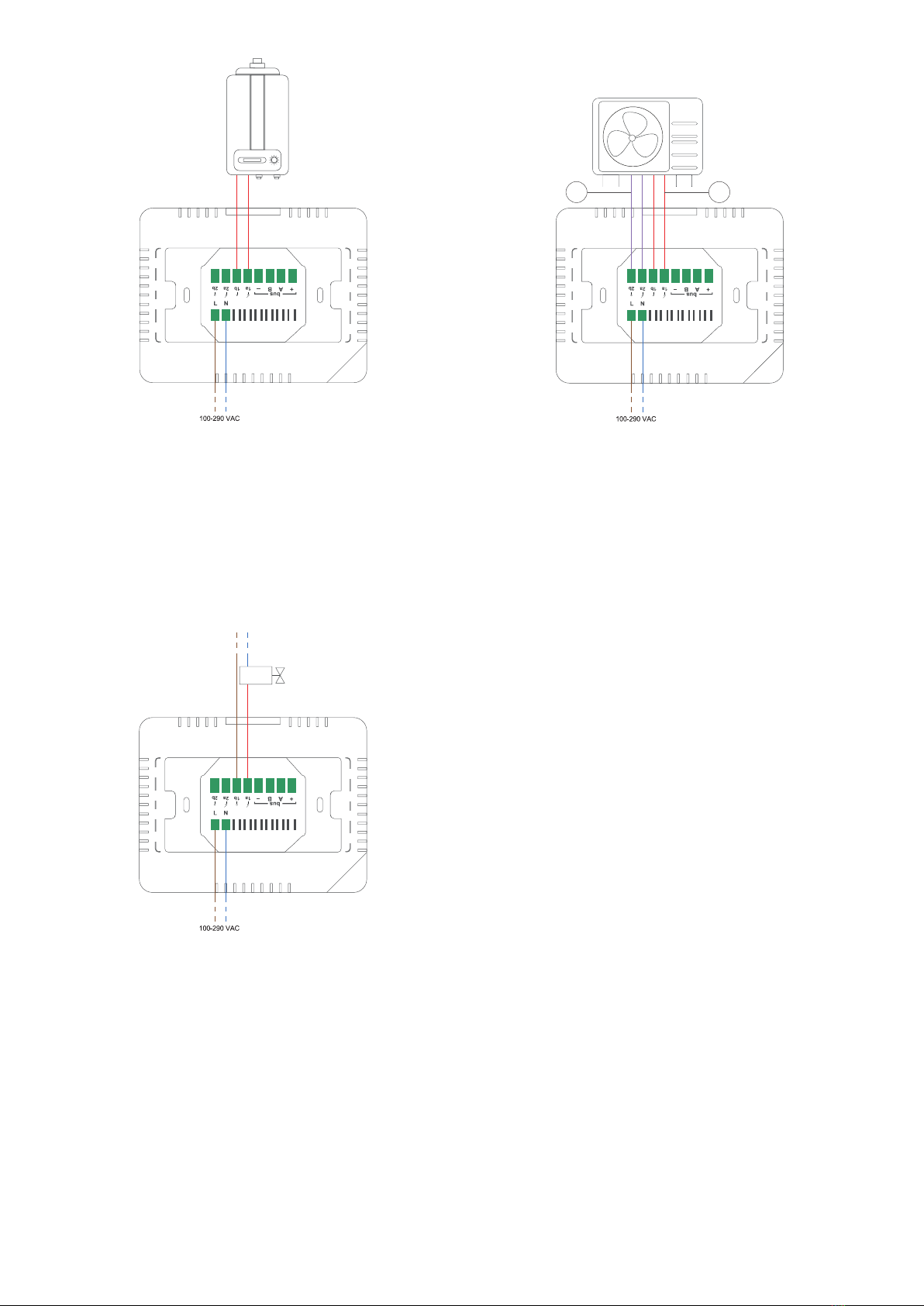
.................................................................................................... 77 CONNECTION DIAGRAM