manuals.online logo
Brands
  1. Home
  2. •
  3. Brands
  4. •
  5. Jaga
  6. •
  7. Thermostat
  8. •
  9. Jaga JRT-200 User manual

Jaga JRT-200 User manual

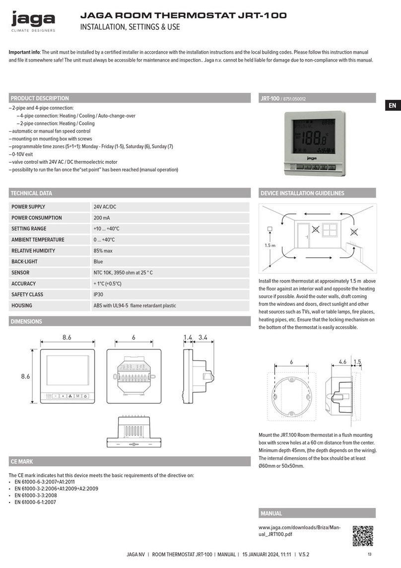
Jaga Room Thermostat JRT-200 installation, setup & user manual
Features
• for 2- and 4-pipe fan coil systems
• heating and cooling mode (4-pipe)
• heating and cooling mode (2-pipe)
• automatic or manual fan speed control
• surface-mounting
• 2 programmable time zones
• 0-10V output
• valves 24V AC/DC or 230VAC
• it is possible (at manual control) to allow the fan to run once “set point” is
reached
Technical Data
Power Supply 24V AC/DC
Power Consumption 200 mA
Set Point Range +10 > +40°C
Ambient 0 > +40°C
Relative Humidity 85% max
Backlight Blue
Sensor NTC 10K
Accuracy + 1°C (step control by +0.5°C)
Protection Class IP30
Housing ABS to UL94-5 fire retardant plastic
Product-documentation:
• this manual is an integral part of the unit and must be handed over to the user
after the installation of the device is completed in order to comply with applicable
legal requirements.
• please read the manual carefully so that you understand the information in order
to ensure safety during installation, use and maintenance.
• no liability is accepted for damage resulting from non-compliance with the
guidelines in this installation manual.
Dimensions
M
M
4.25
6.5
3 2.8
9.3
14
9.7
13.4
1.21.4
0.4
CE-mark
The CE-mark symbolizes the compliance of the device with the following guide-
lines:
• EN 61000-6-3:2007+A1:2011
• EN 61000-3-2:2006+A1:2009+A2:2009
• EN 61000-3-3:2008
• EN 61000-6-1:2007
IMPORTANT: This manual will guide you through the installation, setup and use of the Jaga Room Thermostat JRT-200. Keep this manual in
a safe place for future reference.
JRT-200
ATTENTION !!
1.5 m
The room thermostat must be installed at approx.
1.5 m above floor and out of reach of external influ-
ences such as direct sunlight, draught or other heat
sources as they may impede the correct functioning
of the thermostat. Nearby electric fires, televisions,
wall or table lamps may prevent the thermostat from
working properly.
Ensure that there will be enough space to allow easy
access to the two retaining screws, located at the bot-
tom of the wall plate.
62.8
Mount the JRT-200 Room thermostat on a wall re-
cessed box (60.3 mm fixing centers) or direct onto a flat
wall using wall plugs.
Deze handleiding in het NEDERLANDS:
Ce manuel en FRANÇAIS:
Dieses Handbuch auf DEUTSCH:
This manual in ENGLISH:
www.jaga.be/downloads/Briza/Manual_JRT200.pdf
25 juni 2018, 8:45 - Jaga N.V.
Jaga Room Thermostat JRT-200 installation
Installation
WIRING: Warning: The installation of the thermostat should be performed by qualified personnel and must comply with the applicable
local and national electrical codes and utility requirements. All wire connections must be tightened and properly arranged to prevent
a shortcircuit. Turn off the power at the electrical panel to prevent electrical shock or product damage.
24V AC/DC
M
1234567891011
24V AC/DC
M
1234567891011
24V AC/DC
M
1234567891011
To remove the wall plate, use a Phillips
screwdriver to loosen the two screws from
the bottom of the wall plate
Remove the front panel When not using a recessed conduit box:
• mark out and drill the holes
• screw the device to the wall.
The type of wall, solid or cavity, determines
the type of screw or plug that is used.
24V AC/DC
M
1234567891011
24V AC/DC
M
1234567891011
24V AC/DC
M
1234567891011
• flush wiring can enter from the rear
through the aperture in the wall plate
• connect the JRT-200 according the wiring
diagrams** on this page
Reassemble the front panel Tighten the screws with a Phillips screwdriv-
er. (Do not over-tighten.)
Warning: Turn off the power at the electrical panel to prevent electrical shock or product damage.
** Wiring diagram
2-Pipe 4-Pipe
1234567891011
1234567891011
H/C VALVE
0...10V
COM
0...10V
COM
KEY CARD
-
+
L
N
24V / 220VAC
DC 24V
DC 24V
C VALVE
H VALVE
KEY CARD
-
+
+
+
-
-
L
N
24V / 220VAC
1234567891011
1234567891011
H/C VALVE
0...10V
COM
0...10V
COM
KEY CARD
-
+
L
N
24V / 220VAC
DC 24V
DC 24V
C VALVE
H VALVE
KEY CARD
-
+
+
+
-
-
L
N
24V / 220VAC
H/CHeating / Cooling CCooling
HHeating GND N
25 juni 2018, 8:45 - Jaga N.V.
Jaga Room Thermostat JRT-200 setup / user
Control panel
Clock
Programming & week / day On / Off
Room temperature
Set temperature
M
1234567
h
ROOM
SET
°C
1 2 3 4
Temperature /
parameter setting
Fan Speed setting
Fan speed: Temperature /
parameter setting
Heating / cooling
• Low
• Mid
• High
• Auto fan
Heating
Cooling
Programmable Time setting
• press the “M” button for 5 seconds to enter clock setting ( ) and day setting
• enter 5+1+1 programmable mode
• press “+” and “-“ to set the thermostat on/off time
• next mode setting: toggle trough the menu with the “M” button. Activate the programmed time: press and hold the “ “ button for 5
seconds.
To deactivate the programmed time: press and hold the “ “ button for 5 seconds
Week 1st time zone 2nd time zone
Turn on Turn Off Turn on Turn Off
Icons
1
2 3 4
1
2
3 4
1 2
3
4
1 2 3
4
12345 (Monday~Friday) 8:30 12:00 14:00 18:00
6(Sat.) 9:00 12:00 15:00 18:00
7(Sun.) 9:00 12:00 15:00 18:00
21/12/ 2018, 8:45 - Jaga N.V.
Wiring connections
Disconnect the power supply before making wiring connections, to prevent electrical shock and equipment damage.
Jaga Room Thermostat JRT-200 installation manual
2-Pipe system 4-Pipe system
Briza
Clima Canal
Quatro Canal
....
- 24 VDC
+ 24 VDC
0..10 V
L
+ -
N
230 VAC
L1 N
Briza
Clima Canal
Quatro Canal
....
- 24 VDC
+ 24 VDC
0..10 V
L
+ -
N
230 VAC
L1 N
+-
+-
+-
+-
1234567891011
H/C VALVE
COM
KEY CARD
L
N
24V / 220VAC DCV24
1234567891011
C VALVE
H VALVE
0...10V
KEY CARD
L
N
24V / 220VAC 24VDC
COM
0...10V
Briza
Clima Canal
Quatro Canal
....
- 24 VDC
+ 24 VDC
0..10 V
L
+ -
N
230 VAC
L1 N
Briza
Clima Canal
Quatro Canal
....
- 24 VDC
+ 24 VDC
0..10 V
L
+ -
N
230 VAC
L1 N
+-
+-
+-
+-
1234567891011
H/C VALVE
COM
KEY CARD
L
N
24V / 220VAC 24V DC
1234567891011
C VALVE
H VALVE
0...10V
KEY CARD
L
N
24V / 220VAC DCV24
COM
0...10V
H/CHeating / Cooling CCooling
HHeating GND Ground
Parameter settings
• set Power Off, bij pressing the “ ” button
• to access the MENU , press and hold “M” and “+” buttons simultaneously for 10 seconds until „ “ displays. Press “+” and “-“ to change the
settings.
• toggle trough the menu with the “M” button
Menu Description Range
01 Temp. Offset -8 °C > +8°C, in steps of 0.5 ° C
03 Set Point High Limit +10 °C > +40°C, in steps of 0.5 ° C
04 Set Point Low Limit +10 °C > +40°C, in steps of 0.5 ° C
05 Display setting Room/Set (default Room)
06 Dead Band 0°C > +3°C (default 0,5°C)
07 Programmable Time setting: temperature +10 °C > +20°C, in steps of 0.5 ° C
09 Key-card select NO/NC (default NO)
10 Re-power status keep (default 1) 0:non keep 1:keep
11 2-pipes/4-pipes select 2/4 (default 4)
12 Fan output (0-10V) select dead band or not 0: with dead band 1: without dead band (default 0)
13 Heating / Cooling / Heating + Cooling Heating + Cooling default
14 80% - 90% - 100% fan speed 100% default
15 Back to factory settings
Select 0 or 1 (recovery) with the + and - buttons. After selecting “1”,
press the “ ” button to go to the startup screen. Recovery is success-
ful.
16 Software version 107D

Other manuals for JRT-200

1

Other Jaga Thermostat manuals

Jaga JRT-100TW User manual

Jaga

Jaga JRT-100TW User manual

Jaga JRT-100 User manual

Jaga

Jaga JRT-100 User manual

Jaga JRT-200 User instructions

Jaga

Jaga JRT-200 User instructions

Jaga JRT-100 User instructions

Jaga

Jaga JRT-100 User instructions

Jaga JRT-300 User manual

Jaga

Jaga JRT-300 User manual

Jaga JRT-100TW User manual

Jaga

Jaga JRT-100TW User manual

Jaga JRT-100 User manual

Jaga

Jaga JRT-100 User manual

Jaga JRT-100 User instructions

Jaga

Jaga JRT-100 User instructions

Jaga BRIZA 12 MET JDPC.002 User manual

Jaga

Jaga BRIZA 12 MET JDPC.002 User manual

Jaga JRT-100 User instructions

Jaga

Jaga JRT-100 User instructions

Jaga RDG100 User manual

Jaga

Jaga RDG100 User manual

Popular Thermostat manuals by other brands

EWC Controls EWT-725 installation manual

EWC Controls

EWC Controls EWT-725 installation manual

Seitron wi-time quick guide

Seitron

Seitron wi-time quick guide

Siemens REV23RF operating instructions

Siemens

Siemens REV23RF operating instructions

EWELLY EW-181 manual

EWELLY

EWELLY EW-181 manual

Owon PCT502 quick start guide

Owon

Owon PCT502 quick start guide

Carrier A07048 installation instructions

Carrier

Carrier A07048 installation instructions

Aprilaire 8810M Safety & installation instructions

Aprilaire

Aprilaire 8810M Safety & installation instructions

KMC Controls CTE-1005 installation guide

KMC Controls

KMC Controls CTE-1005 installation guide

Salus Quantum WQ610 quick start guide

Salus

Salus Quantum WQ610 quick start guide

Cosmo CRTD55 manual

Cosmo

Cosmo CRTD55 manual

meitav-tec ETN24-SUPER-SH-F Owner's manual & technnician settings

meitav-tec

meitav-tec ETN24-SUPER-SH-F Owner's manual & technnician settings

CIAT CS2B installation manual

CIAT

CIAT CS2B installation manual

Honeywell Home The Round CT87N owner's manual

Honeywell Home

Honeywell Home The Round CT87N owner's manual

Alpha Easy-Stat 7.2000050 instructions

Alpha

Alpha Easy-Stat 7.2000050 instructions

Airxcel Coleman-Mach 9420 381 Operation guide

Airxcel

Airxcel Coleman-Mach 9420 381 Operation guide

tio TioSmart manual

tio

tio TioSmart manual

Carrier Programmable Thermostats Installation, start-up, and operating instructions

Carrier

Carrier Programmable Thermostats Installation, start-up, and operating instructions

BECA BHT-1000GBLW manual

BECA

BECA BHT-1000GBLW manual

manuals.online logo
manuals.online logoBrands
  • About & Mission
  • Contact us
  • Privacy Policy
  • Terms and Conditions

Copyright 2025 Manuals.Online. All Rights Reserved.