Unico IS18G050 User manual

Bulletin 30-121.2014.04.014
(SAC 37.4255.109.00)
1
Copyright © 2014 Unico, Inc.
INSTALLATION INSTRUCTIONS
- Inverter heatpumpsystem
-
OPERATINGLIMITS
Cooling Maximum conditions
Outdoor temperature : 122 °F (50°C) D.B.
Room temperature : 90 °F (32°C) D.B.
73 °F (23°C) W.B.
Heating Maximum conditions
Outdoor temperature : 75 °F (24°C) D.B.
65 °F (18°C) W.B.
Room temperature : 91 °F (27°C) D.B.
Cooling Minimum conditions
Outdoor temperature : 5 °F (-15°C) D.B.
Room temperature : 50 °F (10°C) D.B.
17 °F (6°C) W.B.
Heating Minimum conditions
Outdoor temperature : -25 °F (-32°C) D.B.
Room temperature : 41 °F (5°C) D.B.
Outdoor - Indoor unit combination table
1, 2, 3, 4 = the refrigerant circuit
connections on the outdoor unit
A, B, C, D = indoor unit size as
shown in following table
Size
Indoor Unit Model Number
A
IS12MPA
B
IS24MPB
U1218L-1EA2AX
C
M2430BL1-EA2 + M2430CL-A
D
M3036BL1-EA2 + M3036CL-A
Power Supply: 208-230V, 1 ph, ~ 60 Hz
system type
outdoor unit
Indoor Unit Size Match
Circuit 1
Circuit 2
Circuit 3
Circuit 4
single split
IS18G050
B
IS24G065
B, C
IS30G080
B, C
IS36G110
B, C, D
dual split
IS18G050
A
A
A
B
IS24G065
A
A
B
A
B
B
IS30G080
A
A
B
A
B
B
C
A
IS36G110
A
A
B
A
B
B
C
A
C
B
tri split
IS24G065
B
A
A
A
A
A
IS30G080
A
A
A
B
A
A
B
B
A
IS36G110
A
A
A
B
A
A
B
B
A
B
B
B
quad split
IS30G080
A
A
A
A
B
A
A
A
IS36G110
A
A
A
A
B
A
A
A
B
B
A
A
B
B
B
A

Bulletin 30-121.2014.04.014
(SAC 37.4255.109.00)
2
Copyright © 2014 Unico, Inc.
IMPORTANT!
Please read before installation
This air conditioningsystem meets strict safety and operating
standards.
For the installer or service person, it is important to install
or service the systemso that itoperatessafelyand efficiently.
For safe installation and trouble-free operation, you
must:
•
Carefully read this instruction booklet before beginning.
•
Follow each installation or repair step exactly as shown.
•
Observe all local, state and national electrical codes.
•
Pay close attention to all warning and caution notices
given in this manual.
•
The unit must be supplied with a dedicated electrical
line.
This symbol refers to a hazard or unsafe practice which
can result in severe personal injury or death.
This symbol refers to a hazard or unsafe practice which
canresultinpersonal injuryorproductor propertydamage.
If necessary, get help
These instructions are all you need for most installation
sites and maintenance conditions.
If you require help for a special problem, contact our
sale/service outlet or your certified dealer for additional
instructions.
In case of improper installation
The manufacturer shallin no waybe responsible for improper
installation or maintenance service, including failure to follow
the instructions in this document.
SPECIALPRECAUTIONS
•
During installation, connect before the refrigerant system
and then the wiring one; proceed in the reverse order
when removing the units.
When wiring
ELECTRICAL SHOCK CAN CAUSE SEVERE
PERSONAL INJURY OR DEATH. ONLY A
QUALIFIED, EXPERIENCED ELECTRICIAN
SHOULD ATTEMPT TO WIRE THIS SYSTEM
•
Do not supply power to the unit until all wiring and tubing
are completed or reconnected and checked, to ensure
the grounding.
•
Highly dangerous electrical voltages are used in this
system. Carefully refer to the wiring diagram and these
instructions when wiring.
Improper connections and inadequate grounding can cause
accidental injury and death.
•
Ground the unit following local electrical codes.
•
The Yellow/Green wire cannot be used for any connection
different from the ground connection.
•
Connect all wiring tightly. Loose wiring may cause
overheating at connection points and a possible fire
hazard.
•
Do not allow wiring to touch the refrigerant tubing,
compressor, or any moving parts of the fan.
•
Do not use multi-core cable when wiring the power supply
andcontrollines.Useseparatecablesfor eachtypeof line.
Whentransporting
Be careful when picking up and moving the indoor and
outdoor units. Get a partner to help, and bend your knees
when lifting to reduce strain on your back. Sharp edges or
thinaluminumfinson the air conditionercancutyourfingers.
When installing...
... In a ceiling or wall
Make sure the ceiling/wall is strong enough to hold the unit-
weight. It may be necessary to build a strong wooden or
metal frame to provide added support.
... In a room
Properly insulate any tubing run inside a room to prevent
"sweating", which can cause dripping and water damage to
walls and floors.
... In moist or uneven locations
Use a raised concrete base to provide a solid level
foundation for the outdoor unit.
This prevents damage and abnormal vibrations.
... In area with strong winds
Securely anchor the outdoor unit down with bolts and a
metal frame. Provide a suitable air baffle.
... In a snowy area (for heat pump-type systems)
Installthe outdoor unit on a raised platform that is higher than
drifting snow. Provide snow vents.
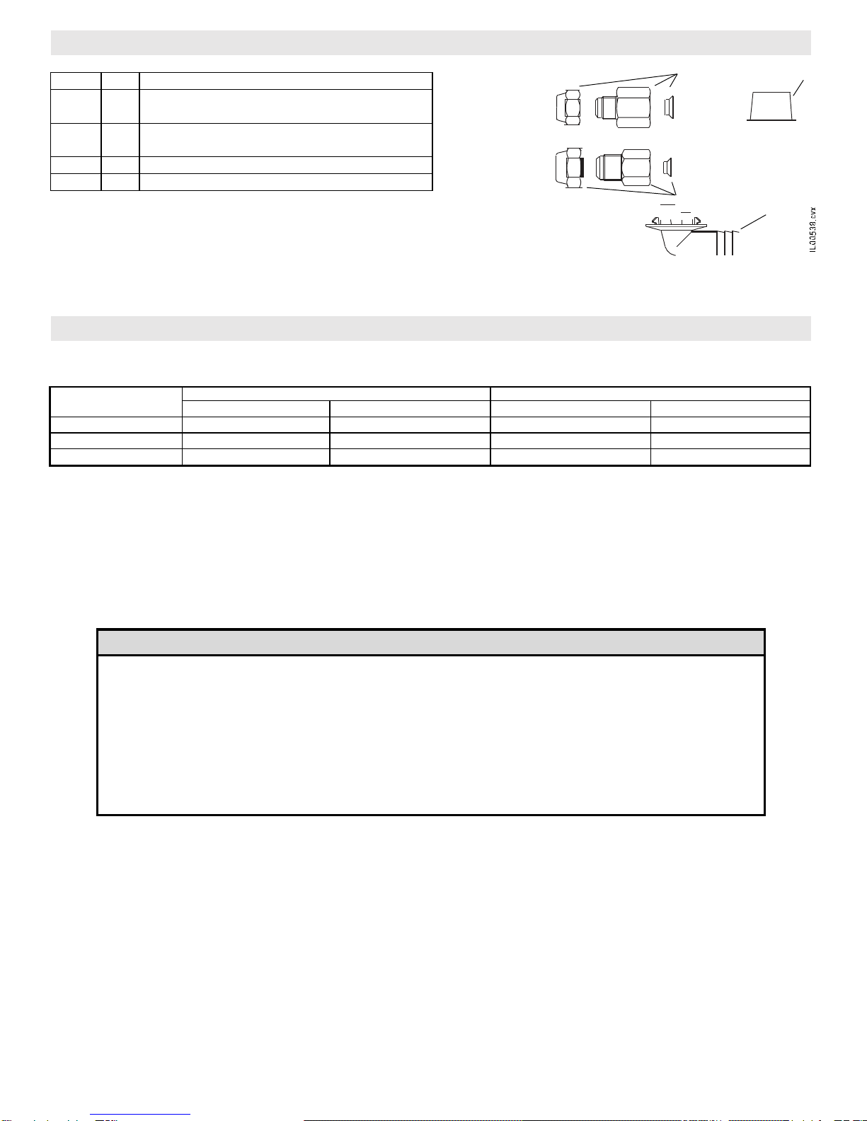
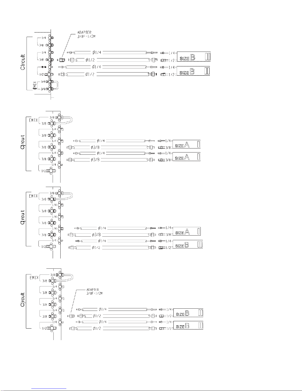
When connecting refrigerant tubing
•
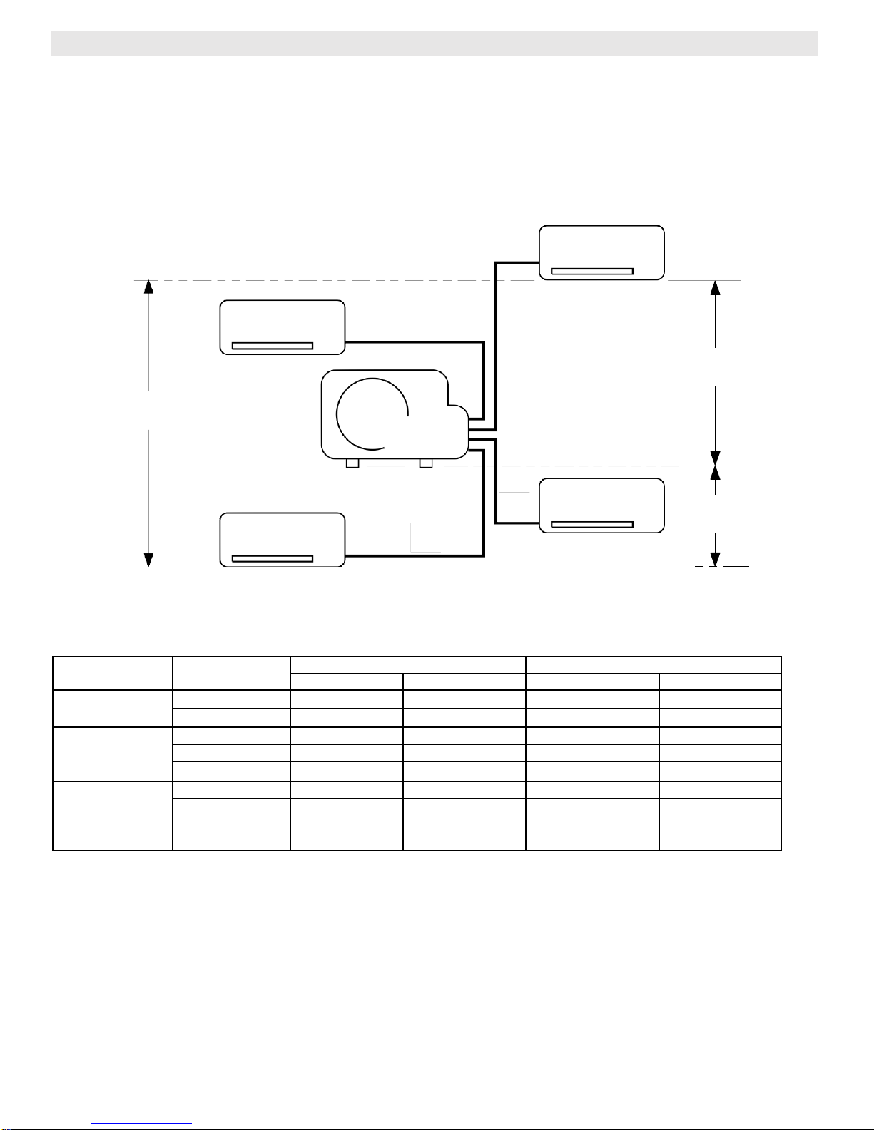
Keep all tubing runs as short as possible.
•
Use the flare method for connecting tubing.
•
Apply refrigerant lubricant to the matching surfaces of
the flare and union tubes before connecting them; screw
by hand and then tighten the nut with a torque wrench
for a leak-free connection.
•
Check carefully for leaks before starting the test run.
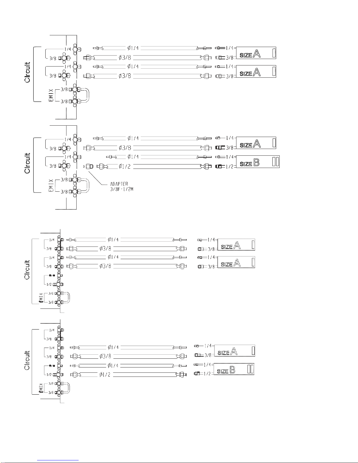
NOTE:
Depending on the system type, liquid and gas lines may
be either narrow or wide. Therefore, to avoid confusion, the
refrigerant tubing for your particular model is specified as
narrow tube for liquid, wide tube for gas.
When servicing
•
Turn the power OFF at the main power board before
opening the unit to check or repair electrical parts and
wiring.
•
Keep your fingers and clothing away from any moving
parts.
•
Clean up the site after the work, remembering to check
that no metal scraps or bits of wiring have been left inside
the unit being serviced.
•
Ventilate the room during the installation or testing the
refrigeration system; make sure that, after the installation,
no gas leaks are present, because this could produce
toxic gas and dangerous if in contact with flames or heat-
sources.
CAUTION
WARNING
WARNING

Bulletin 30-121.2014.04.014
(SAC 37.4255.109.00)
3
Copyright © 2014 Unico, Inc.
Installation site selection - Indoor unit
AVOID
•
Directsunlight.
•
Nearby heat sources that may affect unit
performance.
•
Areaswhereleakageofflammablegasmaybe
expected.
•
Locations where large amounts of oil mist may occur
(such as in kitchen or near factory equipment) because
oil contamination can cause operation problems and
may deform plastic surfaces and parts of the unit.
•
Unsteady locations that will cause noise or possible
waterleakage.
•
Locations where the remote control unit will be
splashed with water or affected by dampness or
humidity.
•
To make holes in areas where electrical wiring or
conduits are located.
DO
•
Select an appropriate position from which every corner
of the room can be uniformly cooled.
•
Select a sufficientlystrong location to support the
weight of the unit.
•
Select a location where tubing and drain hose have
the shortest run to the outside.
•
Allow access for operation and maintenance as well
as unrestricted air flow around the unit.
Installation site selection - Outdoor unit
AVOID
•
Heat sources, exhaust fans.
•
Directsunlight.
•
Damp, humid or uneven locations.
•
Tomakeholesinareaswhereelectricalwiringor
conduitsare located.
DO
•
Choose places as cool as possible and well
ventilated.
•
use lug bolts or equal to bolt down the unit,
reducing vibration and noise.

Bulletin 30-121.2014.04.014
(SAC 37.4255.109.00)
4
Copyright © 2014 Unico, Inc.
1 3
* The IS36G110 provides quantity of 2. 24
The outdoor unit has two drain holes. If drain tube is needed, snap connector
into desired hole and slip plastic drain tube over the barb. Plug the other hole
with the plastic cap.
•
Line set: Deoxidized annealed copper tube for refrigerant tubing connecting the units of the system; it has to be
insulated with insulation, minimum thickness 5/16 inch (8 mm).
INDOOR UNIT SIZE
SMALL TUBE (LIQUID LINE)
LARGE TUBE (VAPOR LINE)
OUTER DIAMETER
MIN. THICKNESS
OUTER DIAMETER
MIN. THICKNESS
A
0.25" (6,35 mm)
0.031" (0,8 mm)
0.375" (9,52 mm)
0.031" (0,8 mm)
B - C
0.25" (6,35 mm)
0.031" (0,8 mm)
0.500" (12,70 mm)
0.031" (0,8 mm)
D
0.375" (9,52 mm)
0.31" (0,8 mm)
0.625" (15,88 mm)
0.031" (0,8 mm)
•
Refrigerant: R410A (if length exceeds standard pre-charge amount)
•
Drain line (if needed): Plastic tubing (I.D. 3/4 inch [18 mm]).
•
Lubrication oil for flare connections (about 1 oz. [30g]).
•
Communication cable: 2-wire shielded cable, 18 ga. (minimum)
•
Electric wire: use insulated copper wires per local codes.
•
Tubinginsulation
Tools required for installation (not supplied)
1. Standard screwdriver
7. Hacksaw
12. Tube flaring tool
2. Phillips head screwdriver
8. Drill bits 5/16" (8 mm) dia.
13. Torque wrench
(Yellow Jacket #60650 or equal)
3. Knife or wire stripper
9. Hammer
14. AdjustableWrench
4. Tape measure
10. Drill
15. Reamer (for de-burring)
5. Level
11. Tube cutter
16. Hex. key
6. Sabre saw or hole saw
ADDITIONAL MATERIAL REQUIRED FOR INSTALLATION (NOT SUPPLIED)
ACCESSORIES SUPPLIED WITH THE OUTDOOR UNIT
Item
Qty
Description
1
1
Adapter, reducer, 3/8M x 1/2F with washer
with washer and flare cap
2
1*
Adapter, reducer, 1/2M x 3/8F with washer
with washer and flare cap
3
1
Cap, pipe, plastic
4
1
Connector, drain, 3/4” (18 mm) hose barb

Bulletin 30-121.2014.04.014
(SAC 37.4255.109.00)
5
Copyright © 2014 Unico, Inc.
L2
There are five rules for the refrigerant tubing related to length and height between components.
#1: (Height) The highest indoor unit must be less than 32 ft above the outdoor unit.
#2: (Height) The lowest indoor unit must be less than 32 ft. below the outdoor unit.
#3: (Height) The highest indoor unit must be less than 19 ft. above the lowest indoor unit.
#4: (Length) The longest distance from any indoor unit to the outdoor unit must be less than L1, L2, L3, L4.
#5: (Length) The sum total of distance of each indoor unit to the outdoor unit must be less than Ltot.
IL00533a.CVX
L Tot. = Total length of all line sets (L1 + L2 + L3...)
Maximum line length allowed
* REQUIRED AMOUNT OF ADDITIONAL REFRIGERANT (R-410A)
For 1/4" x 3/8" line set = 0.16 oz/ft (15g/m)
For 1/4" x 1/2" line set = 0.22 oz/ft (20g/m)
Example: IS18G050 as single-split with 1/4 x 3/8 line set of 60 ft, The excess line length is 35 ft. So add 35x0.16= 5.6 oz.
R-410A.
No additional charge of compressor oil is necessary.
INDOOR UNIT
INDOOR UNIT
L1
L2
maximum
32 ft (10 m)
maximum
19 ft (6 m)
OUTDOOR
UNIT
L3
INDOOR UNIT
INDOOR UNIT
L4
maximum
32 ft (10 m)
TUBING DESIGN LIMITS
Outdoor unit
Number of IDU
PRE-CHARGED (AS SHIPPED)
WITHADDITIONALREFRIGERANT*
L Tot.
L1, L2, L3, L4
L Tot.
L1, L2, L3, L4
IS18G050
SINGLE-SPLIT
25 ft (7.5 m)
-
65 ft (20 m)
-
DUAL-SPLIT
50 ft (15 m)
40 ft (12 m)
100 ft (30 m)
80 ft (25 m)
IS24G065
SINGLE-SPLIT
65 ft (20 m)
-
115 ft (35 m)
-
DUAL-SPLIT
100 ft (30 m)
80 ft (25 m)
150 ft (45 m)
100 ft (30 m)
TRI-SPLIT
100 ft (30 m)
65 ft (20 m)
150 ft (45 m)
80 ft (25 m)
IS30G080
IS36G110
SINGLE-SPLIT
100 ft (30 m)
-
164 ft (50 m)
-
DUAL-SPLIT
130 ft (40 m)
100 ft (30 m)
210 ft (65 m)
100 ft (30 m)
TRI-SPLIT
130 ft (40 m)
100 ft (30 m)
210 ft (65 m)
100 ft (30 m)
QUAD-SPLIT
130 ft (40 m)
100 ft (30 m)
210 ft (65 m)
100 ft (30 m)

Bulletin 30-121.2014.04.014
(SAC 37.4255.109.00)
6
Copyright © 2014 Unico, Inc.
Single-Split (1 Indoor Unit)
For single-split applications, always connect the indoor unit to Circuit “1”of the outdoor unit.
IS18G050
EMIX PORT: SEE EMIX UNIT OR EMIX TANK INSTALLATION MANUAL
IS24G065
IS30G080
4
3
2
1
3
2
1
TUBE CONNECTIONS
1
2

Bulletin 30-121.2014.04.014
(SAC 37.4255.109.00)
7
Copyright © 2014 Unico, Inc.
Single-Split (1 Indoor Unit) –Continued
IS36G110
4
ADAPTER, REDUCER, FLARE
1/4FX3/8M
INCL.WITHINDOORUNIT
2
1
ADAPTER, SPLITTER
1/2FX 3/8FX5/8MINCL.
WITH INDOOR UNIT
4
3
2
1
3

Bulletin 30-121.2014.04.014
(SAC 37.4255.109.00)
8
Copyright © 2014 Unico, Inc.
Dual-Split (2 Indoor Units)
IS18G050
IS24G065
3
2
1
3
2
1
1
2
1
2

Bulletin 30-121.2014.04.014
(SAC 37.4255.109.00)
9
Copyright © 2014 Unico, Inc.
Dual-Split (2 Indoor Units) –Continued
IS24G065
IS30G080 and IS36G110
4
3
2
1
4
3
2
1
4
3
2
1
3
2
1

Bulletin 30-121.2014.04.014
(SAC 37.4255.109.00)
10
Copyright © 2014 Unico, Inc.
Dual-Split (2 Indoor Units) –Continued
IS30G080,IS36G110
IS36G110
4
3
2
1
4
3
2
1

Bulletin 30-121.2014.04.014
(SAC 37.4255.109.00)
11
Copyright © 2014 Unico, Inc.
Tri-Split (3 Indoor Units)
IS24G065
IS30G080,IS36G110
4
3
2
1
4
3
2
1
3
2
1
3
2
1

Bulletin 30-121.2014.04.014
(SAC 37.4255.109.00)
12
Copyright © 2014 Unico, Inc.
Tri-Split (3 Indoor Units) –Continued
IS30G080,IS36G110
IS36G110
4
3
2
1
4
3
2
1

Bulletin 30-121.2014.04.014
(SAC 37.4255.109.00)
13
Copyright © 2014 Unico, Inc.
Quad-Split (4 Indoor Units)
IS30G080,IS36G110
4
3
2
1
4
3
2
1

Bulletin 30-121.2014.04.014
(SAC 37.4255.109.00)
14
Copyright © 2014 Unico, Inc.
Minimum operation and maintenance area Remove the side cover, then connect the power line
and interconnecting wires to outdoor unit on the
terminal strip and secure them with clamps.
Provide a solid base for outdoor unit raised from the
ground level. Fix unit to base using 4 anchor bolts.
IS30G080
4"
(100)
Use insulated copper tube. Cut approximate 12-20
inches (30-50 cm.) longer than actual distance
between units.
min. 0.25" (8 mm) min. 0.25" (8 mm)
Heat pump drain connection. Use, if necessary, the
accessories supplied. Remove plug and insert drain
connection. Then attach plastic tube to the drain
connection by slipping over the barbed end. Use 3/4 inch
(18 mm) plastic tubing.
Plug the other hole with the plastic cap.
Remove burrs at the ends of the copper tubes. Hold
the tube end downward and be sure that no dirt falls
into the tube.
OUTDOOR UNIT INSTALLATION
4"
(100)
16"
(400)
80"
(2000)
80"
(2000)
4"
(100)
20"
(500)
4"
(100)
Dimensionsin inches(mm)
16"
(400)
4"
(100)
Insulation
B
A
D
E
C
F

Bulletin 30-121.2014.04.014
(SAC 37.4255.109.00)
15
Copyright © 2014 Unico, Inc.
Insert flare nuts removed from the units, than make
a flare at the end of copper tubes.
A good flare has the following characteristics:
-
inside surface is glossy and smooth
-
edge is smooth
-
tapered sides are of uniform length.
Follow the instructions of the flaring tool to make the
proper flare.
Apply refrigerant lubricant to the matching surface of
the flare and union before connecting them together.
Avoid putting oil on the threads as much as possible
as this could lead to over-tightening.
Lubricate
approx. 1/8" (3 mm) 45°
Tighten connections using a wrench and a torque
wrench; apply specified torque (see table).
TUBE DIA.
TIGHTENING TORQUE (Approx.)
Insulate tubes leaving connections uncovered for
leak test. Insulate the connection after leak testing.
To prevent refrigerant leaks, be sure to properly form the
flare and to leak test the connection prior to wrapping the
joint with insulation. To prevent the formation of
condensation on the exterior of the connections, fully
insulate the connections.
CAUTION
G
I
H
J

Bulletin 30-121.2014.04.014
(SAC 37.4255.109.00)
16
Copyright © 2014 Unico, Inc.
Air purging of internal unit and refrigerant tubes. Connect the vacuum pump to the outside unit as shown in the figure.
Air and moisture have undesirable effects on the refrigerant system.
VACUUM PUMP CAPACITY
26.4 gal/h (100 /h)
Tubing length:
less than 33 ft (10 m)
Tubing length
longer than 33 ft (10 m)
10 min. or more
15 min. or more
K

Bulletin 30-121.2014.04.014
(SAC 37.4255.109.00)
17
Copyright © 2014 Unico, Inc.
M
Connect the indoor units using, if required, the adapter on the low
pressure valves. Remove caps from service valves of both tubes.
Then start vacuum pump and let it run for the time indicated in the table
in step K (vacuum 500 microns Hg abs.).
High pressure
Low pressure
With vacuum pump still running close the low pressure knob on valve
manifold. Then stop vacuum pump. Using a hexagonal key, open the
service valve on small tube, then close it after 10 seconds. Check tightness
of all joints using liquid soap.
Turn the service valves stem in counterclockwise to fully open the valves. At
this point vacuum pump flexible hose can be disconnected. Replace bonnet
and flare nut, tighten them to 15 lb-ft (200 kg-cm) with a torque wrench.
Repeat what described from L to M for the second, third and fourth circuit.
The indoor units have to be marked as “indoor unit circuit 1, 2, 3 and 4”. Be
sure that the refrigerant connection to indoor unit circuit 1, 2, 3 or 4
corresponds to its own electrical connection.
TO
EMIX
EMIX
UNIT
FROM
EMIX
UNIT
UNIT
UNIT
UNIT
TO
EMIX
EMIX
UNIT
FROM
EMIX
UNIT
UNIT
UNIT
UNIT
L

Bulletin 30-121.2014.04.014
(SAC 37.4255.109.00)
18
Copyright © 2014 Unico, Inc.
* The service port on the wide tube service valve uses a Schrader core valve to
access the refrigerant system. Therefore, be sure to use a hose connector which
has a push-pin inside.
NOTE: THE SERVICE VALVE REQUIRES A 5/16” Female SAE x 1/4" Male SAE
HOSEADAPTER.
EXAMPLE: GRAINGER P/N: 3DXH5 (J/B MODEL QC-S5S) OR EQUAL
Complete insulation of refrigerant tubes; wrap with insulation tape. Fix and support tubes with brackets. Seal hole in
the wall, if necessary.
SERVICE VALVE INSTRUCTIONS
P

Bulletin 30-121.2014.04.014
(SAC 37.4255.109.00)
19
Copyright © 2014 Unico, Inc.
1 INDOOR UNIT
1 INDOOR UNIT
SYSTEM WIRING DIAGRAM

Bulletin 30-121.2014.04.014
(SAC 37.4255.109.00)
20
Copyright © 2014 Unico, Inc.
POWERSUPPLY
AC 208-240V1
PHASE 50/60 Hz
POWERSUPPLY
AC 208-240V1
PHASE 50/60 Hz
2 INDOOR UNITS
2 INDOOR UNITS
Other manuals for IS18G050
1
This manual suits for next models
3
Table of contents
Other Unico Heat Pump manuals
Popular Heat Pump manuals by other brands

Tebas
Tebas INVERTER S Instruction handbook

Glen Dimplex
Glen Dimplex LA 33TPR Maintenance Instruction

STIEBEL ELTRON
STIEBEL ELTRON WWK 221 electronic Operation and installation

Mitsubishi Heavy Industries
Mitsubishi Heavy Industries HMA60-S Technical manual

York
York Sunline 2000 BCH 036 installation manual

Carrier
Carrier AQUAZONE 50PTH Installation and service instructions