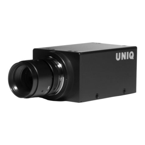
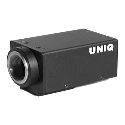
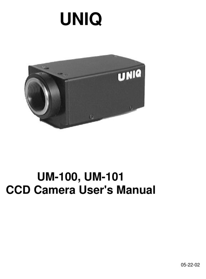
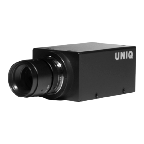
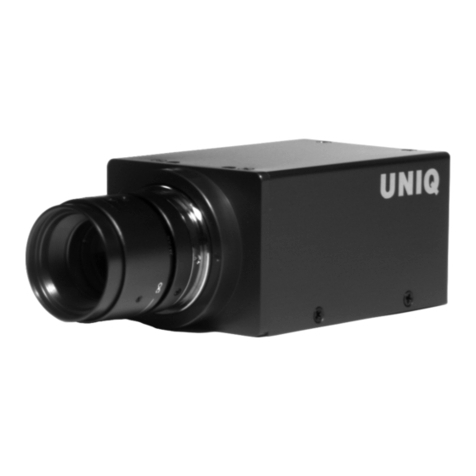
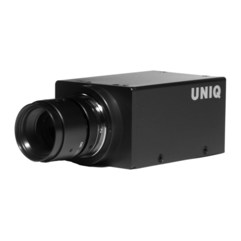
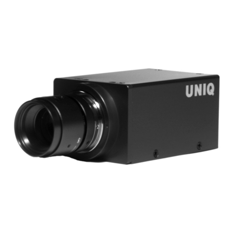
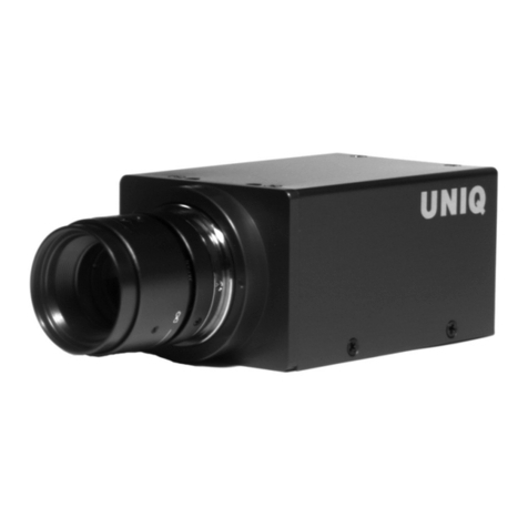
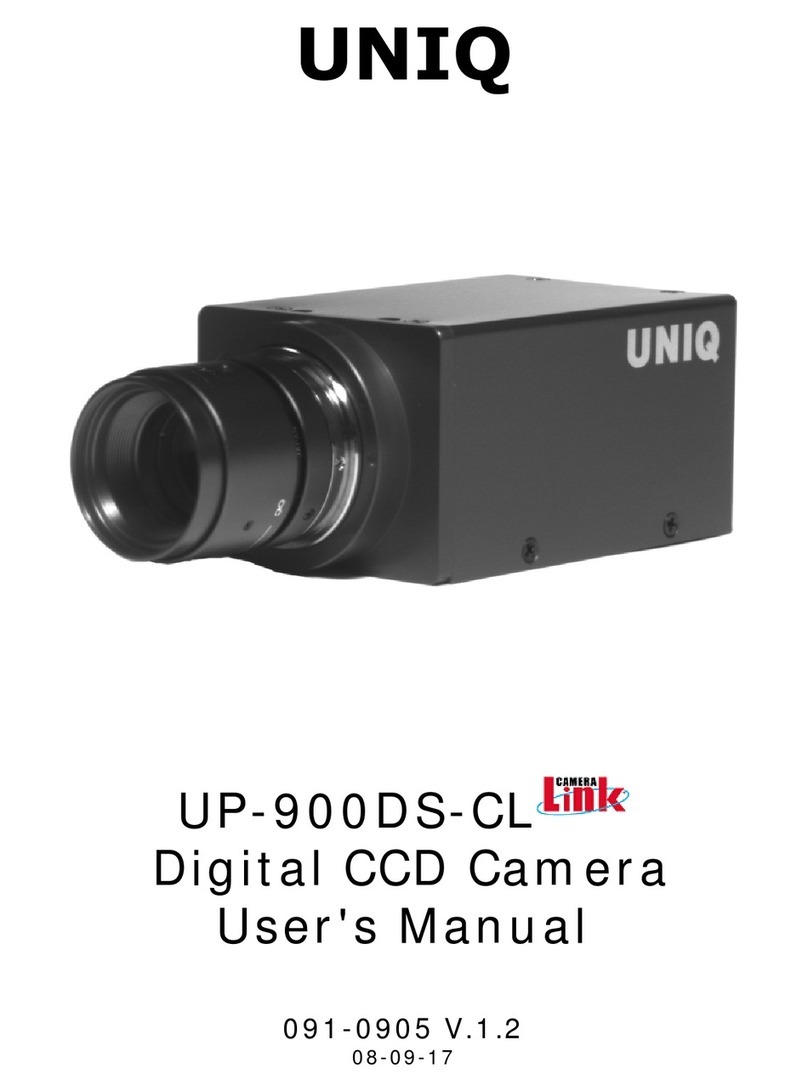
Uniq UP-680 User manual

UNIQ
UP-680/UP-680CL
B/WDigital CCDCamera
User'sManual
091-0680 V.1.3
07-22-04

1
Tableof Contents
Warning ................................................................................................................. 2
Precautions ............................................................................................................2
Limited Warranty ................................................................................................... 2
1.Introduction .......................................................................................................3
2.CameraSetup .....................................................................................................5
3.CameraFunctions .............................................................................................. 5
4.RS-232C Communication Control ...........................…........................................ 10
5.Digital InterfaceTiming ..................................................................................... 12
6.CameraFunctional Timing ................................................................................. 13
7.CameraAccessories ……………….............…..........................................................15
8.CameraMalfunction .......................................................................................... 16
9.Technical SupportInformation .......................................................................... 17

2
WARNING
TO PREVENT FIREORELECTRIC SHOCK HAZARD,
DONOT EXPOSETHISCAMERAUNITTO RAINORMOISTURE.
DONOT ATTEMPTTO REMOVECAMERACOVERORMODIFYTHECAMERAUNIT,
WARRANTYWILL BEVOIDED.
PRECAUTIONS
Do dotattempttodisassemble,modify,or repairthe camera.ContactUNIQfor help.
Do notpointthe cameraatbrightobjects,suchasthe sun,for along period.Itmay
cause CCDblooming and permanentdamages.
Do notoperatethe camerabeyond the temperature range.Avoid using the camera
above90% humidity.
Do notuse unregulated power supply source.
Do nottouchCCDglass cover withfingers or any hard objectsother thanprofessional
glass cleaning solvents.
Limited Warranty
UNIQwarrantstothe original customer tobefree from defectsinmaterial and
workmanship for twofull years from the dateoforiginal purchase.Thiswarranty covers
failures or damages due todefectsinmaterial or workmanship,whichoccur during
normal use.Itdoes notcover damages or failures,whichresultfrom shipment,
mishandling,abuse,misuse,or modification.
AReturn Material Authorization (RMA)number isrequired prior toreturning any UNIQ
productfor repairor replacement.
Thisproprietary documentmay notbereproduced or photocopied withoutthe consentof
UNIQ.UNIQmakes no warranty or assumes no responsibility for any errors,whichmay
appearinthisdocument. UNIQreserves the righttomakechanges withoutnoticeor
obligation.
For immediatetechnical assistance,please call (408) 330-0818 or email to
tech@uniqvision.com

3
1.Introduction
1.1General Description
TheUP-680/UP-680CL isa10-bit,659 x 494 full frameresolutiondigitalCCD camerausing
progressivescanninginterline-transfer technology.Thesquare pixelsare especially suitablefor
processing,measuring,andanalyzingtasks.Highspeedmovingobjectscaneasily becaptured
with theexternalasynchronouscapture control.Thiscompactandlightweight cameraoffers
excellent signaltonoiseperformance.It’scompatiblewith mostpopularframegrabbersin the
market.The“user-friendly”RS-232Cinterfacecontrolallowsuserstocontrolall camerafunctions
without physically touchingthecamera.
1.2Features
•1/2”ProgressivescanCCD imager
•659 x 494 activepixels
•10-bit RS-644/CameraLink output
•Full frameshutter (1/60 ~1/62,000 sec.)
•<58 dB
•Asynchronouscapture
•60 Hzframerate(120Hzbinning)
•25 MHzdataclock
•Long-term frameintegration
•Externalexposure control
•RS232Cinterfacecontrol
•C-mount lens
1.3Applications
UP-680/UP-680CL applicationsincludehigh-speedmachinevision,automatedinspection,motion
capture andanalysis,andother industrialapplications.
1.4CCDImagerSpectral ResponseCurve

4
1.5CameraSpecifications
Model
UP-680 UP-680CL
CCD Sensor 1/2” HyperHAD progressivescaninterline-transferCCD
ChipSize 7.48 mm x6.15 mm
EffectivePixels(HxV) 659 x494
UnitCell Size(HxV) 9.9 µmx9.9 µm
Pixel Clock 25 MHz(50 MHzformasterclock)
Frame Rate 60 FPS(120 FPSVertical binning)
Sync. HD: 31.485KHz;VD: 59.972 Hz
Digital VideoOutput 10-bitRS-644 CameraLinkformat
AnalogVideoOutput 1Vp-p,75ohm (BNCor12 pinHirose)
S/N Ratio <58 dB
Min.Illumination 0.1lux
Gain MGC
Gamma 1.0
ElectronicShutter 1/60 ~1/62,000 selectable16 steps
LensMount C-Mount
OperatingTemperature -10 °C ∼+50 °C
PowerRequirement 12VDC,250mA,3.0W
Dimension 50mm x39mm x83mm
Ext.Sync. Internal/External Auto Switch
AsynchronousReset Standard
Weight 200 g
1.6CameraDimension

5
2.Camera Setup
A basiccameraandframegrabber system setup,asshownin Figure 1 below, requiresaUP-
680/UP-680CL camera, astandardC-mount lens,aPS-12Cpower supply orequivalent,aPC
system andaVGA monitor,aframegrabber,andanexternaltrigger deviceif necessary.
Figure 1.CameraandFrameGrabber System Setup
3.Camera Functions
3.112-PinConnector
The12-pin Hiroseconnectorislocatedonthe
rearpanelof thecamera. All groundsignals
onpin 1,3,5,and8 are commongrounds.
+12 VDC input isrecommendedonpin 2,but
thiscamerashouldwithstand+12 V ±1V
input voltage.Makesure tosettheNM/AM
switchtoNM positionforexternalHDandVD
locking.ForHD(pin 6)andVD(pin 7)
inputs,TTLsignalsare required(see section
6.6 fordetails).Forasynchronouscapture
(VINT)applications,refer tosection6 for
details.ForRS-232Cinterfacecontrolviathis
12-pin connector,usepin #10 and#12.
Figure 2 belowshowsatopviewofthe12-pin
Hiroseconnector.
Pin No. UP-680 UP-680CL
1 GND
2 +12VDCinput
3 GND
4 Video
5 GND
6 External HD N/C
7 Ext.VD/VINT N/C
8 GND
9 N/C
10 RX(RS-232C) N/C
11 Integration control
12 TX(RS-232C) N/C
Figure 2.12-Pin HiroseConnector

6
3.2ModeSwitchesSelection
Designation:
NS-Functionalselect
DS-Shutter speedselect
NR-RS-232Ccommunication Enable
RI-Rearswitchcontrol Enable
NP-Reservedforcustom options
PS-Reservedforcustom options
NM-Normalmode
AM-Asynchronousmode
Timingdetailsof themodeswitchesare shownin section6.
3.3ShutterSpeedDial Switch
Shutter speeddialswitchislocatedontherearpanelandthere are 16 different positions.To
selectcameragain,reference,ortosaveauser page,setNS/DS switchtoNS position.Toadjust
shutter speed,setNS/DStoDSposition.Fornormalshutter speed,makesure tosetNM/AMmode
toNM location.Forasynchronouscapture,setNM/AMmodetoAMlocation.
ShutterSpeedSelect (DS)
Normal Speed DoubleSpeed
Position No. Functional Select
(NS) Shutter
Speed (sec)
(NMMode)
Asynchronous
Capture(sec)
(AM Mode)
Shutter
Speed (sec)
(NMMode)
Asynchronous
Capture(sec)
(AM Mode)
0 Normal 1/60 1/60 1/120 1/120
1 GainAdjustment 1/125 1/250 1/250 1/250
2 ReferenceAdjustment 1/250 1/500 1/500 1/500
3 FactoryPage 1/500 1/1000 1/1000 1/1000
4 UserPage 1 1/1000 1/2000 1/2000 1/2000
5 UserPage 2 1/2000 1/4000 1/4000 1/4000
6 UserPage 3 1/4000 1/5000 1/5000 1/5000
7 UserPage 4 1/5000 1/6000 1/6000 1/6000
8 Normal/DoubleSpeed 1/6000 1/8000 1/8000 1/8000
9 Reserved 1/8000 1/10000 1/9000 1/10000
A Reserved 1/10000 1/12000 1/10000 1/12000
B Reserved 1/12500 1/15000 1/12500 1/15000
C Reserved 1/15000 1/20000 1/15000 1/20000
D Reserved 1/20000 1/31000 1/20000 1/31000
E Reserved 1/31000 1/62000 1/31000 1/62000
F Reserved 1/62000 PulseWidth
Control 1/62000 PulseWidth
Control
Figure4.ShutterSpeed Dial Switch
Figure
3.Mode switches

7
3.4MomentarySwitch(UP/DownSwitch)
Position
No. Functional Select(NS) Up/DownSwitch
0 Normal N/A
1 GainAdjustment Moveupordownto adjustgain
2 ReferenceAdjustment Moveupordownto adjustreference
3 FactoryPage Moveupordownto recall factorypage
4 UserPage 1 Up:Recall;Down:Save
5 UserPage 2 Up:Recall;Down:Save
6 UserPage 3 Up:Recall;Down:Save
7 UserPage 4 Up:Recall;Down:Save
8 Normalspeed/Doublespeed
Up:Normal speed;Down:Doublespeed
9 Reserved
A Reserved
B Reserved
C Reserved
D Reserved
E Reserved
F Reserved
Camerasettingscanbesavedintofourdifferent user pages.Oncetheuser pageissavedandset
betweenshutter speeds4 and7,it will beactivatedaslongasthecameraispoweredON.User
Pageworks in both rearplatecontrolandRS232Ccommunicationselections.
3.5GainControl (AGC/MGC)
Note: Thisgainpotentiometer only applies tocameraswithoutUp/Downswitch
on rearplate.
Manual gaincontrol (MGC)
MGCisstandardfactorysettingonthiscamera. Themanualgain controlcanbeadjustedfrom4dB
to36 dB.Adjustingthegain potentiometer locatedonrearpanelwill changethegain value.
Automaticgaincontrol (AGC):
AGCisnotavailableandit isnotrecommendedtouse.ContactUNIQforfurther details.
Figure 6.Gain potentiometer
Figure 5.Up/DownSwitch

8
3.6Digital OutputPinoutandConnector
3.6.140-PinD-SubConnector
PIN SIGNAL I/O NOTE PIN SIGNAL I/O NOTE
1 +12VIN/OUT I/O 21 RESERVED
2 GND 22 RESERVED
3 CLK+ O RS644/LVDS 23 HD I TTL
4 CLK- O RS644/LVDS 24 GND
5 FEN+ O RS644/LVDS 25 VD / VINT I TTL
6 FEN- O RS644/LVDS 26 RESERVED
7 LEN+ O RS644/LVDS 27 INT I TTL
8 LEN- O RS644/LVDS 28 RESERVED
9 DATA0+ O RS644/LVDS 29 DATA1+ O RS644/LVDS
10 DATA0- O RS644/LVDS 30 DATA1- O RS644/LVDS
11 DATA2+ O RS644/LVDS 31 DATA3+ O RS644/LVDS
12 DATA2- O RS644/LVDS 32 DATA3- O RS644/LVDS
13 DATA4+ O RS644/LVDS 33 DATA5+ O RS644/LVDS
14 DATA4- O RS644/LVDS 34 DATA5- O RS644/LVDS
15 DATA6+ O RS644/LVDS 35 DATA7+ O RS644/LVDS
16 DATA6- O RS644/LVDS 36 DATA7- O RS644/LVDS
17 DATA8+ O RS644/LVDS 37 DATA9+ O RS644/LVDS
18 DATA8- O RS644/LVDS 38 DATA9- O RS644/LVDS
19 RESERVED 39 RESERVED
20 RESERVED 40 RESERVED
Note:
1.DATA9+/- ismostsignificant bits.
2.DATA0+/- isleastsignificant bits.
3.Pin #1(+12VIN/OUT)of40-pin digitalconnectorandpin #2(+12V)of12-pin Hiroseconnector
are connected.If12V power isprovidedfrom12-pin connector,pin #1ofthe40-pin connector
will actasa+12V output.
Figure7.40 pindigital connector

9
3.6.226-PinCameraLink Connector:
PIN NO. CAMERALINK
SYMBOL UNIQCAMERA
SYMBOL FUNCTION
1,14 INNER SHIELD SHIELD Innershielding
2,15 X0-,X0+ DATA0-,DATA0+
Video,LEN andFEN dataoutput
3,16 X1-,X1+ DATA1-,DATA1+
Video,LEN andFEN dataoutput
4,17 X2-,X2+ DATA2-,DATA2+
Video,LEN andFEN dataoutput
5,18 Xclk-,Xclk+ CLK-,CLK+ Pixel clockoutput
6,19 X3-,X3+ DATA3-,DATA3+
Video,LEN andFEN dataoutput
7,20 SerTC+,SerTC- Rx+,Rx- Differential pair,serial communicationsfrom frame
grabber
8,21 SerTFG-,SerTFG+Tx-,Tx+ Differential pair,serial communicationsto frame
grabber
9,22 CC1-,CC1+ HD-,HD+ CameraControl 1(CC1)-Horizontal signal input
10,23 CC2+,CC2- VINT/VD+,
VINT/VD- CameraControl 2(CC2)-Vertical signal or
asynchronousresetinput
11,24 CC3-,CC3+ Reserved Reserved forcustom options
12,25 CC4+,CC4- Reserved Reserved forcustom options
13,26 INNNER SHIELD SHIELD Innershielding
Figure 8.3M26-pin CameraLink Connector(MDR-26 pin)
10
4.RS-232CCommunicationControl
4.1HyperTerminal Program
UNIQdoesnotprovideitsownsoftware program forRS-232Ccommunication.Inorder touseRS-
232Cinterface,aHyper Terminalsoftware program mustbeinstalledandapplied.Thefollowing
showshowtorun anduseof Hyper Terminal.
Windows95/98/Me/2000/XP
HowdoIrun Hyper Terminal?
1.Click Start/Programs /Accessories
2.Within accessoriesdoubleclick Hyper Terminal(If youdonotsee Hyper terminalclick the
communicationsfolder andthenclick Hyper Terminal).If youare unabletolocateHyper Terminal
it may notbeinstalledsee nextquestion.
HowdoIuninstall /reinstall /install HyperTerminal?
1.Click Start/Settings/ControlPanelanddoubleclick Add RemovePrograms.
2.Within Add RemovePrograms click theWindowsSetuptab.
3.Doubleclick thecommunicationsicon.
4.Andcheck oruncheck theHyper Terminalsectiondependingif youwant Hyper
Terminaltobeinstalledoruninstalled,if youwant toreinstall Hyper Terminal
uncheck andthenclick ok andthenrepeattheaboveprocess andre-check Hyper
Terminal.
For firsttimeuser ofHyper Terminal,gotoProperties,
Select9600 bitsper second inConfigure…
Enable“Echo typed characters locally”boxinASCII setup…
4.2RS232Ccommunicationsettingrequirement:
BaudRate 9600 bps
Parity None
Data 8 bit
StartBit 1 bit
StopBit 1 bit
Xon/Xoff None
GotoHyper Terminalprogram
- Click Fileandclick Properties
- Click Settingstab
- Click ASCII Setup…
- InASCII Sendingsection,
check Echotypedcharacterslocally but uncheck Sendlineendswith linefeeds
4.3RS-232CCommandPinout(LVDS only):
Command 12-pin HiroseConnector 40-pin DigitalConnector
TX Pin #12 Custom requestonly
RX Pin #10 Custom requestonly
Note: IfRS-232Cisvia9-pin D-subconnectoratPC end,makesure toshortorconnectpin #4
and#6,andthenshortorconnectpin #7 and#8,but donotconnectall 4 pinstogether.

11
4.410-BitCameraRS-232 Command
Command CommandName Notes
? Error “?” Errorwill appearon screenif incorrectcommandisentered
ru#Recall userpage Musthaveanumberafter“ru” suchas 1,2,3or4
rp Reportcurrent
camerasetting G =Gain;R =Reference
S=ShutterMode;NS,NM(referto rearplatesetting)
rf Recall factory
settingpage Factorydefaultsetting
sm#Shuttermode Musthaveanumberaftersm(1~f),referto section 3.3fordetails.
sp#Saveuserpage Thereare4userpage available
ns Normal speed Referto cameraspecifications
ds Doublespeed Referto cameraspecifications
nm Normal mode Normal free running
am Asynchronousmode
Asynchronousreset
gi### Gainincrease ### =Hexadecimals(000 ~3ff).If no numberentered,gainwill be
increased byfactorof 1.If anumberisentered,thennumberwill be
added to stored gain.
gd### Gaindecrease ### =Hexadecimals(000 ~3ff).
Sameas gi above,exceptitwill be decreased.
gn### Gainnumber### =Hexadecimals(000 ~3ff).Referto thegaincurvesbelowfor
details. Onlyonecurveappliesto eachcameradependingon camera
model,contactUNIQforfurtherdetails.
bi### Referenceincrease
bd### Referencedecrease
bn### Referencenumber
### =Hexadecimals(000 ~3ff).If no numberentered,reference
will be increased byfactorof 1.If anumberisentered,thennumber
will be added to stored reference.
Note:It’sveryuncommon to change referencelevel,contactUNIQfor
furtherdetails.
Note:
1.Commandmustbein “lower case.”
2.All numbershavetobein “hex”format,useaPC calculatortoconvertbetweenhex and
decimalnumbersif necessary.
3.Commandexample:
User Enters:“sm5”(shutter speedat5)
Camerareturns:“?”or“3f”in Hex
(incorrectanswer,noRS232Ccommunicationorsomething’swrong)
or
Camerareturn:“ ”or“1”in Hex (correctanswer,it might showother
symbolsdependingonPC system)
4.Gain Curves:
Figure 9.CameraGain Curves

12
5.Digital InterfaceTiming
5.1Pixel Clock
5.2LineEnable
5.3FrameEnable
5.4FrameEnableforVertical Binning
Note:
1.Pixelclock =25MHz
2.1 N=40 nsec.
3.1 H=793 N

13
6.CameraFunctional Timing
6.1Free Run (shutterspeedposition0,60 fps)
6.2Free Run (shutterspeedpositionfrom1toF)
6.3Asynchronous Capture(shutterspeedposition0)
6.4Asynchronous Capture(shutterspeedpositionfrom1toE)
6.5Asynchronous CapturewithPulseWidthControl (shutterspeed: F)

14
6.6External SynchronizationandGen-lock (viaCameraLinkinterfaceONLY)
TheUP-680/UP-680CL cameraautomatically locks totheexternalsyncsource.Theexternalsync
sourcemustmatchthecameraHDandVDspecification,whichare 31.49KHzand59.97Hz
respectively.Both externalHDandVDare TTLlevelsignals.
a)HD
H:2.5V to5V
L:0V orGND
Pulsewidth:5-50%duty cycle,see figure 8 shownbelow.
b)VD
H:2.5V to5V
L:0V orGND
Pulsewidth:0.5-50%duty cycles
Figure 10.ExternalSynchronizationandGen-lock Timing
6.7Integration (via12-pinHirose connector ONLY)
TheUP-680/UP-680CL cameracanbeintegratedupto2 secondswithout severe noiseordark
current effect.Tostartintegration,pin #11 (sameaspin #27 of 40-pin digitalconnector) of the
12-pin connectormustbeconnectedtoGND or0V.Theintegratedvideowill beshiftedout
followingthenextverticaldriveafter pin #11 goesback tohighor5V level,asshownin figure 9
below. If aframegrabber doesnotcapture theimmediateframeorintegratedvideo,thenormal
video(before theintegration)will display again onthemonitor.
Figure 11.IntegrationControlTiming

15
7.Camera accessories
7.1PowerSupplyandPowerCable
12 V DC regulatedpower supply with 1A current output orbetter isrecommended.Thiscamera
usesHirose12-pin connectorforpower source.Themattingcableplugconnectorcanbe
purchasedthroughdistributorsorUNIQandtheHirosepartnumber is HR10A10P12S.UNIQ
providespower suppliesandpower cablesas"onestopshopping"forcustomers.Alternatively,the
power suppliesandpower cablescanbepurchasedthroughpower supply andcablevendors.
ContactUNIQforvendorlist.
7.2Lens
C-mount lensisthestandardlensforUP-680/UP-680CL camera. There are avariety of C-mount
lensesin themarketthatworks with UP-680/UP-680CL camera. Makesure thequality and
specificationof thelensmatchthecamera'sapplication.Someof themostpopularlensesin the
market,such asCosmicar,Fujinon,Rodenstock, and Schneider,are recommended.
7.3Digital ConnectorandCable
7.3.140-pinDigital ConnectorandCable
UNIQstocks standardandcustom cablesforcustomer'sconvenience.Theseare highquality and
flexibletwistedpaired,overall shieldedcables.ContactUNIQformore details.
Thematingcableplugconnectorandback shell kitsare madeby AMP.
AMP: 749111-3 cableplugconnectorwith covers.
AMP: 749192-1 back shell kitswith latches
7.3.2CameraLink Cable
CameraLink cablecanbepurchasedfrom 3M,Mouser,framegrabber vendorsorUNIQ.

16
8.Camera Malfunction
WARNING:DONOT ATTEMPTTO OPENTHECAMERAHOUSINGINANYCASEWITHOUT
CONSENTINGTHEFACTORY.
Cameramalfunctionrarely happens.Incasecameramalfunctions,thefollowingtroubleshooting
procedureswouldhelptominimize theproblem;it definitely helpstheuser tofindout theactual
problem andmay saveatripforsendingthecameraback tothefactory.
a)Firstof all,unplugthepower supply anddisconnectthe12-pin Hirosepower connectorandany
attachedcable(s)fromthecameraunit.Makesure there isnothingconnectedtothecameraatthis
time.
b)Closeall necessary framegrabber software filesonthecomputer.
c)Check the12V DC power supplyatthe12-pin connectorcableandmakesure it doesprovidethe
correctvoltagetothe12-pin connector.If it doesnot,replaceagoodpower supply andproceed
thefollowingsteps.
d)Makesure tosetthecamerashutter dialswitchandmodeswitchesatthecorrectposition(refer
tosection4,timingsignals,fordetails.)
e) Now,power upthecamerawith framegrabber cable(s)connectedtothecameraandtheframe
grabber.Click onUP-680/UP-680CL configurationfilefrom theframegrabber'sconfigurationfile
list.If all theabovecameraandframegrabber setupproceduresare donecorrectly,agoodimage
shouldbeappearedonadisplay monitor.
f)If it failstoshowany goodimages,check theinterfacecablepinouts,both cameraandframe
grabber end,consult UNIQorframegrabber manufacturer if necessary.Also,makesure theUP-
680/UP-680CL cameraconfigurationfileiscorrect.
g)If problem still exits,contactUNIQorframegrabber manufacturer forfurther assistance.
h)If livevideodoesexit but it'snotgoodorclean,check framegrabber configurationfilesettings
orcontactUNIQorframegrabber manufacturer forassistance.
i)"Idogetthevideobut it'stoo dark." Makesure thelensiswideopenandshutter speeddial
switchisat"no"shutter or"lowspeed"shutter.
J)Point thecameraatabright scenewithout alenson,ablankorbright displayshouldbeseenon
adisplay monitor.CoveringtheCCD camerawith handorlenscap shouldsee adark video.If no
videooccurs,mostlikely theCCD cameraisdamaged,assumingthatall setupprocedureswere
donecorrectly above.Consult cameratechnicalsupportatthefactory.
k)If there isagoodvideobut it isnotcleanorbad,it ispossiblethattheCCD imager glass is
dirty,ortheCCD cameracouldbepartially damaged.Usehigh-pressure airtoblowthedirtaway
ontheCCD protectiveglass surfaceif theCCD glass isnotclean.If theproblem still exists,
contacttheUNIQtechnicalsupportforhelp.

17
l)If there isagoodvideobut theRS232Ccommunicationfails,orif thecameradoesnotrespond
after sendingacommand,makesure tocheck thefollowing.
i)GotoHyper Terminalprogram
Click Fileandclick Properties
Click Settingstab
Click ASCII Setup…
InASCII Sendingsection,check Echotypedcharacterslocally but uncheck Sendline
endswith linefeeds
ii)IfRS-232Cisvia9-pin D-subconnectoratPC end,makesure toshortorconnectpin #4
and#6,andthenshortorconnectpin #7 and#8,but donotconnectall 4 pins
together.
9.Technical SupportInformation
Fortechnicalassistance,contactUNIQTechnicalSupportorApplicationsEngineer at
Phone: (408)330-0818
Fax:(408)330-0886
Email:tech@uniqvision.com
Company contactinformation:
UNIQVISION,INC.
3220 Scott Blvd.
SantaClara, CA 95054
Phone: (408)330-0818
Fax:(408)330-0886
Ourwebsite: www.uniqvision.com
SalesInquiries: info@uniqvision.com
TechnicalSupport: tech@uniqvision.com
This manual suits for next models
1
Table of contents
Other Uniq Security Camera manuals

Uniq
Uniq UC-900DS-CL User manual

Uniq
Uniq UP-1800CL User manual

Uniq
Uniq UC-1800DS-CL User manual

Uniq
Uniq USS-600CL User manual

Uniq
Uniq UC-1800CL User manual

Uniq
Uniq UP-685CL User manual

Uniq
Uniq UC-800CL User manual

Uniq
Uniq UP-2000CL User manual

Uniq
Uniq UC-600CL User manual

Uniq
Uniq Camera Link UC-930CL User manual