Uniq UP-1800CL User manual

UP-1800CL
CameraLink Camera
User's Manual
091-1800 V.1.4
08-09-17

1
Table of Contents
Warning.................................................................................................................2
Precautions............................................................................................................2
Limited Warranty ...................................................................................................2
1. Introduction.......................................................................................................3
2. CameraSetup.....................................................................................................5
3. CameraFunctions..............................................................................................5
4. RS-232C Communication Control ...........................…........................................9
5. Digital InterfaceTiming.....................................................................................10
6. CameraFunctional Timing.................................................................................11
7. CameraAccessories……………….............…..........................................................13
8. Technical Support ..............................................................................................13

2
WARNING
TOPREVENT FIREOR ELECTRIC SHOCK HAZARD,
DO NOTEXPOSE THIS CAMERAUNITTORAIN ORMOISTURE.
DO NOTATTEMPT TOREMOVE CAMERACOVER ORMODIFYTHECAMERAUNIT,
WARRANTY WILLBEVOIDED.
PRECAUTIONS
Do dotattempt to disassemble, modify, orrepair thecamera.ContactUNIQforhelp.
Do notpointthecameraatbrightobjects,such as thesun,foralongperiod.It may
causeCCDbloomingandpermanentdamages.
Do notoperate thecamerabeyondthetemperature range.Avoidusingthecamera
above 90% humidity.
Do notuseunregulated power supplysource.
Do nottouch CCDglass cover with fingersoranyhard objectsotherthan professional
glass cleaningsolvents.
Limited Warranty
UNIQ warrantstotheoriginal customer to befree fromdefectsin material and
workmanshipfortwofullyearsfromthedate oforiginal purchase. Thiswarranty covers
failures ordamagesdueto defects in material orworkmanship, whichoccurduring
normaluse. It doesnotcover damagesorfailures,whichresultfromshipment,
mishandling,abuse, misuse, ormodification.
AReturnMaterial Authorization(RMA)number isrequired priortoreturninganyUNIQ
productforrepair orreplacement.
Thisproprietary documentmaynotbe reproduced orphotocopied withouttheconsentof
UNIQ.UNIQ makesno warrantyorassumesno responsibility foranyerrors, which may
appearin thisdocument. UNIQreservestherightto make changeswithoutnoticeor
obligation.
Forimmediate technical assistance, pleasecall (408)330-0818 oremail to
tech@uniqvision.com

3
1. Introduction
1.1 General Description
The UP-1800CLisa10-bitdigitalCCDcamerausing progressive scansensor.This compact and
lightweight cameraoffersexcellent signalto noise performance at areasonableprice. The square
pixelsareespecially suitableforprocessing, measuring, and analyzing tasks. High speedmoving
objects canbe captured with the externalasynchronous capturecontrol.
1.2 Features
•2/3” Exview HAD (NIR) Progressive Scan CCD Imager
•1390 x1037 active pixels
•15 Hzframe rate
•2x2(694 x518)Binning at30 FPS
•10-bitCameraLink digital output
•Analogoutput
•Fullframe shutter
•<58 dB
•Asynchronous reset at fullframe shutter
•27 MHz pixelclock
•RS-232C interfaceControl
•C-mountlens
1.3 Applications
UP-1800CL applications include machine vision, automatedinspection, motioncaptureand
analysis, high-resolutiongraphics capture, medical imaging, biomedicalimaging, non-contact
measurement, microscopy, and other scientific and industrialapplications wherenearinfrared
(NIR) and high sensitivity is required.
1.4 CCD Imager Spectral ResponseCurve

4
1.5 Camera Specifications
Model
UP-1800CL
CCD Sensor 2/3” Exview HAD progressive scan interline-transfer CCD
Chip Size 10.20 mm x8.30 mm
Effective Pixels (H x V) 1390 x1037
Unit Cell Size (H x V) 6.45
µ
mx6.45
µ
m
Pixel Clock 27 MHz
Frame Rate 15 FPS (30 FPS for 2x2binning)
Sync. HD: 15.733 KHz; VD: 14.998 Hz
Digital Video Output Camera Link format
Analog Video Output 1 V p-p, 75ohm (BNC or 12 pin Hirose)
S/N Ratio <58 dB
Min. Illumination 0.02 lux
Gain MGC
Gamma 1.0
Electronic Shutter 1/15 ~ 1/32,000 selectable
Lens Mount C-Mount
Operating Temperature -10
°
C
∼
+55
°
C
Power Requirement 12V DC, 280mA, 3.4 W
Dimension 50mm x39mm x83mm
Ext. Sync. Internal/External Auto Switch
Asynchronous Reset Standard
Weight 200 g
1.6 Camera Dimension

5
2. Camera Setup
Abasiccameraand frame grabber system setup,as showninFigure1below,requiresaUP-
1800CL camera, astandardC-mountlens, aPS-12C power supplyor equivalent, aPC system with
amonitor,aframe grabber,and an externaltrigger deviceif necessary.
Figure1. Cameraand Frame GrabberSystem Setup
3. Camera Functions
3.1 12-Pin Connector
The 12-pin Hirose connector is located onthe
rear panelof the camera. All ground signals
onpin1, 3, 5, and 8arecommongrounds.
+12 VDC input isrecommended onpin2, but
thiscamerashouldwithstand +12 V ±1V
input voltage. Make sureto set the NM/AM
switch toNM positionforexternalHD and VD
locking. Figure2belowshows atopview of
the 12-pinHirose connector.
PinNo. UP-1800CL
1 GND
2 +12VDC input
3 GND
4 Video
5 GND
6 N/C
7 N/C
8 GND
9 N/C
10 N/C
11 Integrationcontrol
12 N/C
Figure2. 12-PinHirose Connector

6
3.2 Mode Switches Selection
Designation:
NS-Functionalselect
DS-Shutter speed select
NR- RS-232C communication Enable
RI-Rear switch control Enable
NP- Reserved forcustomoptions
PS- Reserved forcustomoptions
NM-Normalmode
AM-Asynchronous mode
Timing detailsof mode switches willbe described insection6.
3.3 Shutter Speed Dial Switch
Shutter speed dial switch islocated onthe rearpaneland thereare16 different positions. To
adjust cameragain,reference orsave to auser page, set NS/DS switch to NSposition. To adjust
shutter speed, set NS/DS to DS position. For normalshutter speed, make sureto set NM/AM mode
to NM location. For 2x2binning, set NS/DS to NS position, turn16-step dial switch to
No.8and select DSthen set NS/DS to DS thistime for 2x2binning shutter speed selection.
For asynchronous captureapplications, set NM/AMmode to AM location.
Position No.Functional Select (NS)
Shutter Speed Select (DS)
Shutter
Speed (sec)
(NM Mode)
Shutter
Speed (sec)
(DS Mode)
Asynchronous
Capture for normal and
binning (sec)
(AM Mode)
0 Normal 1/15 (Off) 1/30 (Off) No shutter
1 Gain Adjustment 1/30 1/60 1/500
2 Reference Adjustment 1/60 1/80 1/750
3 FactoryPage 1/120 1/120 1/1000
4 User Page 1 1/250 1/250 1/2000
5 User Page 2 1/500 1/500 1/3000
6 User Page 3 1/1,000 1/1,000 1/3500
7 User Page 4 1/2,000 1/2,000 1/4000
8 Normal/2x2binning 1/3,000 1/3,000 1/4500
9 Reserved 1/4,000 1/4,000 1/5000
A Reserved 1/5,000 1/5,000 1/6000
B Reserved 1/6,000 1/6,000 1/7500
C Reserved 1/7,500 1/7,500 1/10,000
D Reserved 1/10,000 1/10,000 1/15,000
E Reserved 1/15,000 1/15,000 1/32,000
F Reserved 1/32,000 1/32,000 Pulse Width Control
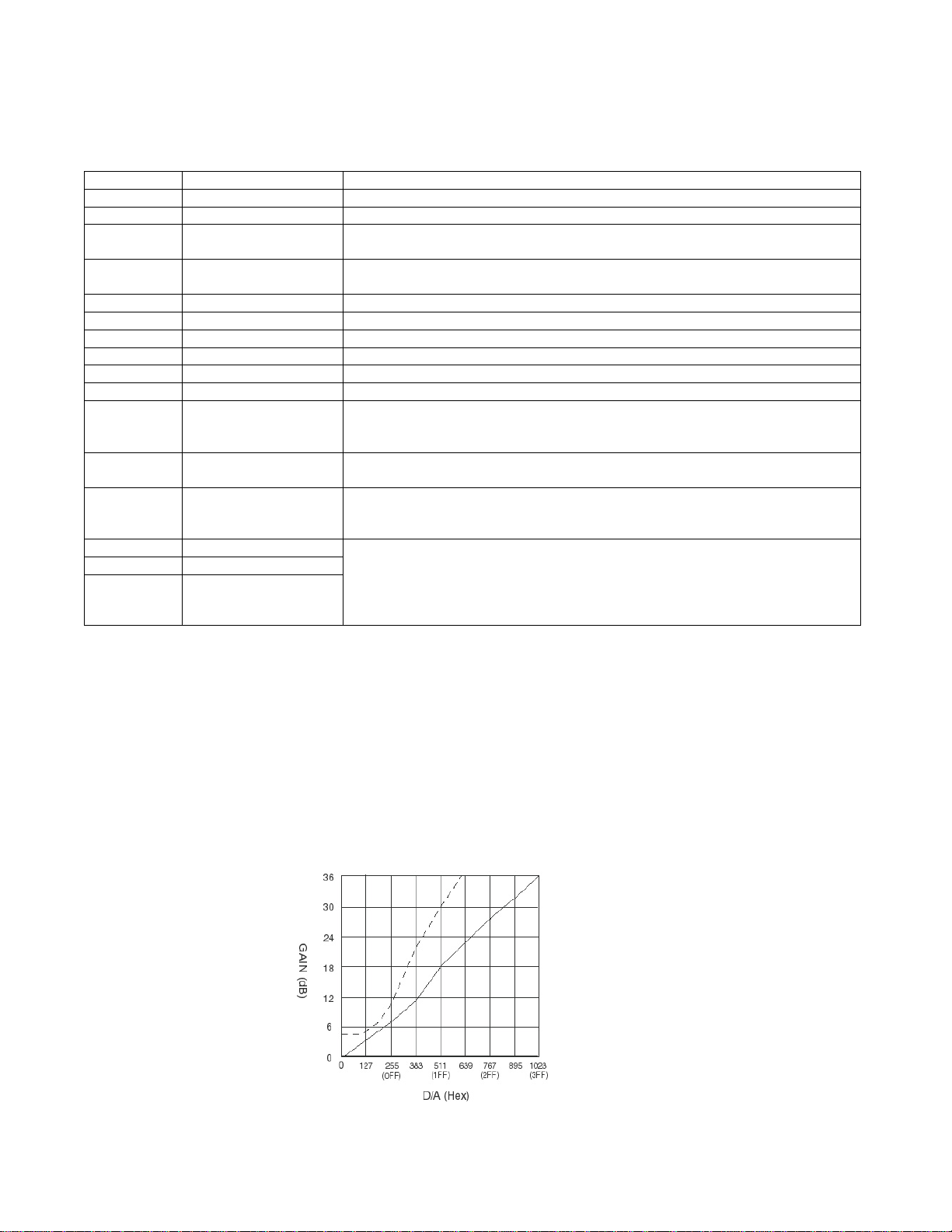
Figure 4. Shutter Speed DialSwitch
Figure 3. Mode switches

7
3.4 Momentary Switch (UP/Down Switch)
Position
No. Functional Select (NS) Up/Down Switch
0 Normal N/A
1 Gain Adjustment Move up or down toadjust gain
2 Reference Adjustment Move up or down toadjust reference
3 FactoryPage Move up or down torecall factorypage
4 User Page 1 Up: Recall;Down: Save
5 User Page 2 Up: Recall;Down: Save
6 User Page 3 Up: Recall;Down: Save
7 User Page 4 Up: Recall;Down: Save
8 Normal/2x2binning Up: Normal speed; Down: 2x2binning
9 Reserved
A Reserved
B Reserved
C Reserved
D Reserved
E Reserved
F Reserved
Camerasettings canbe savedinto four differentuser pages. Once the user page issaved and set
between shutter speeds 4and7, itwillbe activated as long as the camerais powered ON. User
Page works inboth rearplatecontroland RS232C communicationselections.
3.5 Gain Control (AGC/MGC)
Note:Thisgain potentiometer onlyappliesto cameras withoutUp/Down switch
on rearplate.
Manual gain control (MGC)
MGC isstandardfactorysetting onthiscamera. The manualgaincontrol can be adjusted from4dB
to 36 dB. Adjusting the gainpotentiometer locatedonrearpanelwillchange thegainvalue.
Automaticgain control (AGC):
AGC isnotavailable and itisnotrecommended to use. Contact UNIQfor further details.
Figure6. Gainpotentiometer
Figure5. Up/Down Switch

8
3.6 26-Pin Camera Link Connector
PIN NO. CAMERA LINK
SYMBOL UNIQ CAMERA
SYMBOL FUNCTION
1, 14 INNER SHIELD SHIELD Inner shielding
2, 15 X0-,X0+ DATA0-,DATA0+
Video,LEN and FEN data output
3, 16 X1-,X1+ DATA1-,DATA1+
Video,LEN and FEN data output
4, 17 X2-,X2+ DATA2-,DATA2+
Video,LEN and FEN data output
5, 18 Xclk-,Xclk+ CLK-,CLK+ Pixel clockoutput
6, 19 X3-,X3+ DATA3-,DATA3+
Video,LEN and FEN data output
7, 20 SerTC+,SerTC- Rx+,Rx- Differential pair,serialcommunications from frame
grabber
8, 21 SerTFG-,SerTFG+Tx-,Tx+ Differential pair,serialcommunications to frame
grabber
9, 22 CC1-,CC1+ HD-,HD+ Camera Control 1(CC1) - Horizontal signal input
10,23 CC2+,CC2- VINT/VD+,
VINT/VD- Camera Control 2(CC2) - Vertical signal or
asynchronous reset input
11,24 CC3-,CC3+ Reserved Reserved for custom options
12,25 CC4+,CC4- Reserved Reserved for custom options
13,26 INNNER SHIELD SHIELD Inner shielding
Figure8. 3M 26-pinCameraLinkConnector (MDR-26 pin)

9
4. RS-232C Communication Control
UNIQ doesnotprovide its own softwareprogramfor RS232C communication, contact frame
grabber vendor or UNIQ for further details.
Command Command Name Notes
? Error “?” Error will appear on screen if incorrect command isentered
ru# Recall userpage Must have a number after “ru” such as 1, 2,3or 4
rp Report current
camera setting G= Gain; R = Reference
S = Shutter Mode; NS,NM (refer to rear plate setting)
rf Recall factory
setting page Factorydefault setting
sm# Shutter mode Must have a number after sm (1~ f),referto section 3.3for details.
sp# Save user page There are 4user page available
ns Normal speed Refer to camera specifications
ds Double speed Refer to camera specifications
nm Normal mode Normal free running
am Asynchronous modeAsynchronous reset
gi### Gain increase ### = Hexadecimals(000~ 3ff).If nonumber entered,gain will be
increased byfactor of 1. If a number is entered,thennumber will be
added tostored gain.
gd### Gain decrease ### = Hexadecimals(000~ 3ff).
Same as giabove,except it will be decreased.
gn### Gain number ### = Hexadecimals(000~ 3ff).Refer tothe gain curves below for
details.Onlyone curve appliesto each camera depending on camera
model,contact UNIQ for further details.
bi### Reference increase ### = Hexadecimals(000~ 3ff).If nonumber entered,reference
willbe increased byfactor of 1.If anumber is entered,then number
willbe added to stored reference.
Note: It’sveryuncommon to change reference level,contact UNIQ for
further details.
bd### Reference decrease
bn### Reference number
Note:
1. Command must be in “lowercase.”
2. Allnumbershave tobe in“hex” format, use aPC calculator to convertbetween hex and
decimal numbersifnecessary.
3. Command example:
UserEnters: “sm5” (shutter speed at 5)
Camerareturns: “?” or “3f”in Hex
(incorrectanswer,no RS232C communicationor something’s wrong)
or
Camerareturn: “ ”or “1” inHex (correct answer,itmight showother
symbolsdepending onPC system)
4. Gain Curves:
Figure9.CameraGainCurves

10
5. Digital Interface Timing
5.1 Pixel Clock
5.2 Line Enable
5.3 Frame Enable
5.4 Pixel Clock for 2x2 binning mode
5.5 Line Enable for 2x2 binning mode
5.6 Frame Enable for 2x2 binning mode

11
6. Camera Functional Timing
6.1 Free Run (shutter speed position 0, 15 fps)
6.2 Free Run (shutter speed position from 1 to F)
6.3 Asynchronous Capture (shutter speed position 0)
6.4 Asynchronous Capture (shutter speed position from 1 to E)
6.5 Asynchronous Capture with Pulse Width Control (shutter speed:F)

12
6.6 External Synchronization and Gen-lock (viaCameraLinkinterfaceONLY)
The UP-1800 cameraautomaticallylocks tothe externalsync source. The external sync source
must match the cameraHD and VD specification, which are15.73KHz and 14.98Hz respectively.
Both externalHD and VD areTTLlevelsignals.
a) HD
H: 2.5V to 5V
L:0V or GND
Pulse width:5-50% duty cycle, see figure8shown below.
b) VD
H: 2.5V to 5V
L:0V or GND
Pulse width:0.5-50% duty cycles
Figure10.ExternalSynchronizationandGen-lockTiming
6.7 Long Term Integration (via12-pinHiroseconnector ONLY)
The UP-1800CL cameracan be integrated up to 2seconds. To startintegration, pin#11 ofthe 12-
pinconnector must be connected to GND or 0V.The integrated video willbeshifted out following
the next verticaldriveafter pin#11 goes back to high or5V level,as shown infigure9below. Ifa
frame grabber does notcapturethe immediate frame orintegrated video,the normal video(before
the integration) will display againonthe monitor.Ifintegrationis preferred to controlviaCamera
Link interface, consultUNIQfor furtherdetails.
Figure11.IntegrationControl Timing

13
7. Camera accessories
7.1 Power Supply and Power Cable
12 VDC regulated power supplywith 1A current output or betterisrecommended. Thiscamera
uses Hirose 12-pinconnectorforpower source. The matting cable plug connector can be
purchased through distributorsor UNIQ and the Hirose partnumberis HR10A10P12S.UNIQ
provides power suppliesand power cables as"one stopshopping"forcustomers. Alternatively,the
power suppliesand power cables can be purchased through power supplyand cablevendors.
Contact UNIQfor vendor list.
7.2 Lens
C-mountlens isthe standardlens for UP-1800CL camera.ThereareavarietyofC-mount lenses in
the market that workswith UP-1800CL camera.Make surethe quality and specificationof the lens
match thecamera'sapplication. Some of the most popularlenses inthe market, such as
Cosmicar, Fujinon,Rodenstock, andSchneider,arerecommended.
7.3 Camera Link Cable
CameraLink cablecan be purchased from3M, Mouser,Digi-Key and frame grabber vendors.
8. Technical Support Information
For technical assistance, contact UNIQTechnicalSupportor Applications Engineer at
Phone: (408) 330-0818
Fax: (408) 330-0886
Email:info@uniqvision.com
Company contactinformation:
UNIQ VISION, INC.
2924 ScottBlvd.
Santa Clara, CA 95054
Phone: (408) 330-0818
Fax: (408) 330-0886
Our website: www.uniqvision.com
General Inquiries: info@uniqvision.com
Table of contents
Other Uniq Security Camera manuals

Uniq
Uniq UM-100 User manual

Uniq
Uniq UC-600 User manual

Uniq
Uniq USS-680CL User manual

Uniq
Uniq USS-600CL User manual

Uniq
Uniq UP-685CL User manual

Uniq
Uniq Camera Link UC-930CL User manual

Uniq
Uniq UC-685CL User manual

Uniq
Uniq UC-1800CL User manual

Uniq
Uniq UC-2000CL User manual

Uniq
Uniq UP-900CL User manual