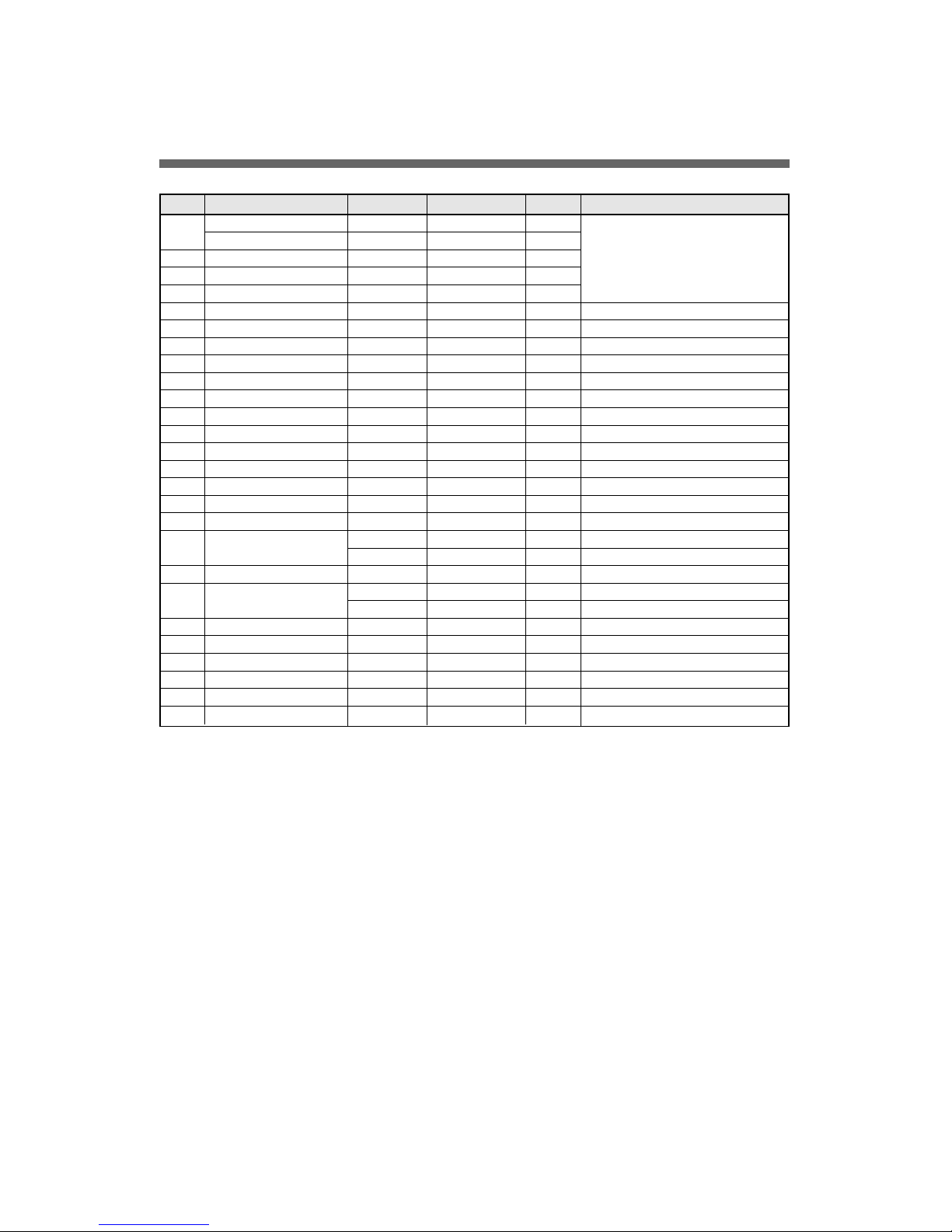
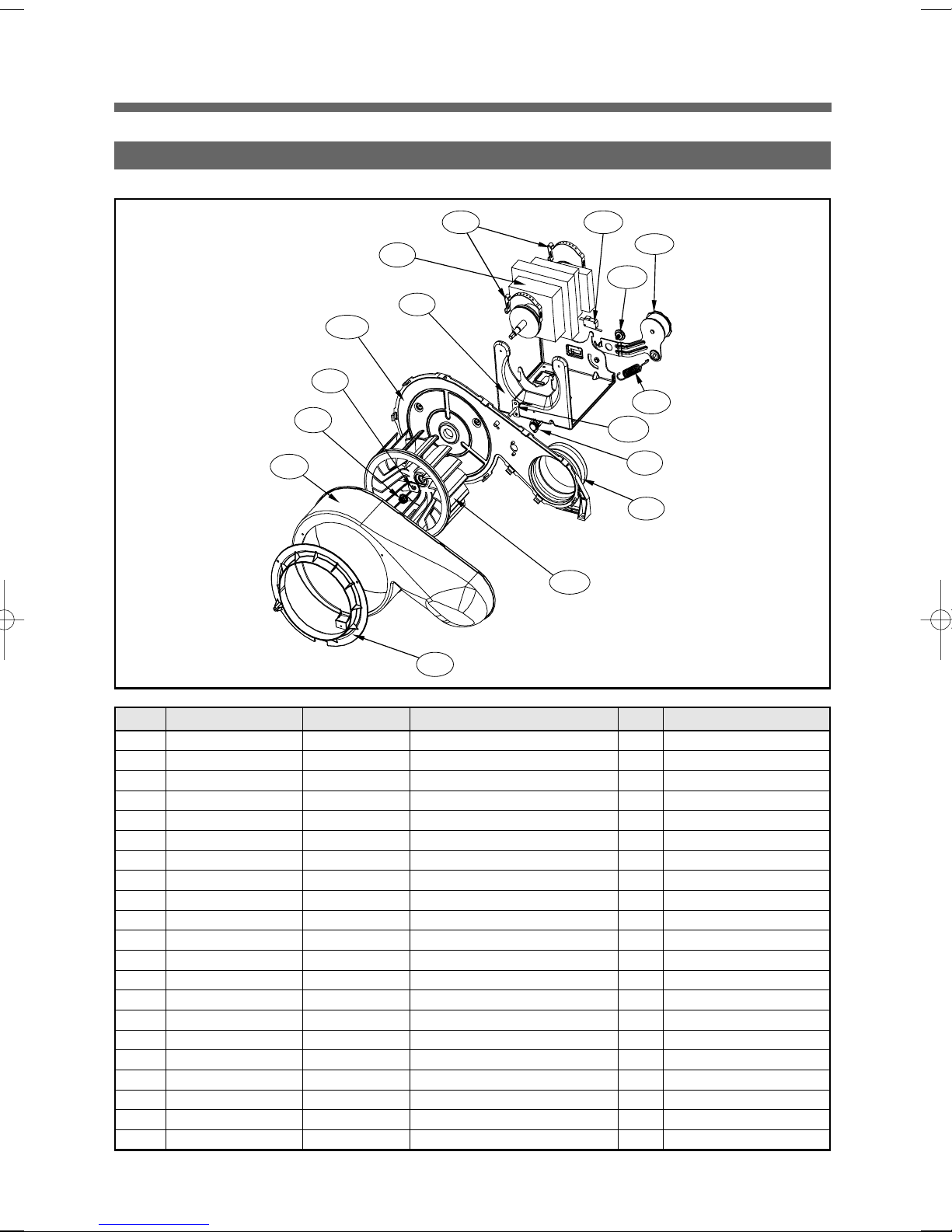
No. Part Name Part Code Description Qtt'y Remark
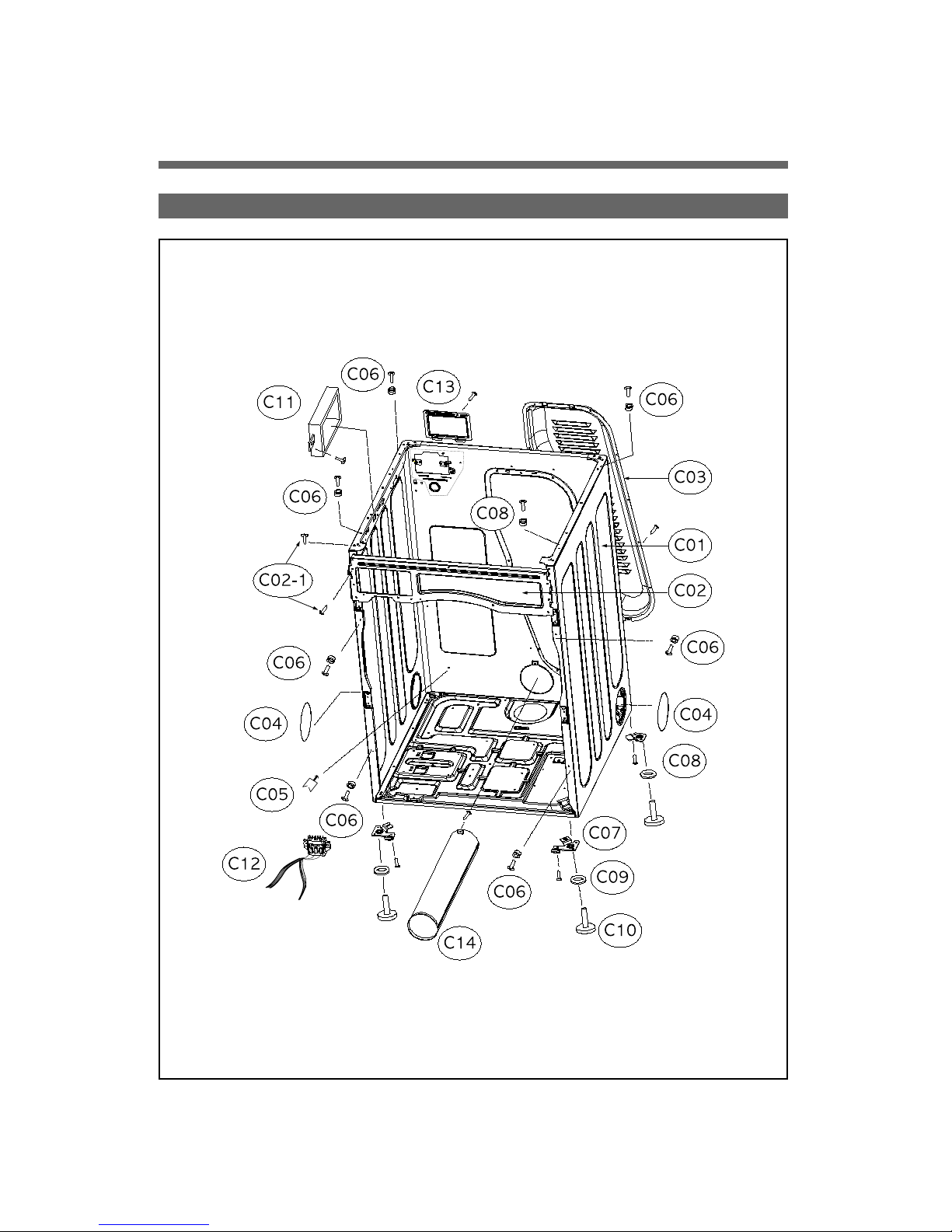
C01 CABINET(ELECTRIC) 3610812350 SGCC0.8T 1
CABINET(GAS) 3610812360 SGCC0.8T 1
C01-1 FRAMETOPL 3612206500 SGCC1.6T 1 1PIECE SVCPART
C01-2 FRAMETOP R 3612206600 SGCC1.6T 1
C01-3 BASEUNDER 3610392900 SGCD0.8T 1
C02 LOCKHARNESS M 3612207900 NYLON 12
C03 FRAMEUPPER 3612207900 SGCC1.2T 1
- SCREWTAPPING 7121401411 T2STRS 4x14 6 For fixingFrame UppertoCabinet
C04 COVERBACK 3611427900 SGCC0.6T 1
- SCREWTAPPING 7112401411 T1TRS4x14 12 ForfixingCover Back
C05 COVERDUCT 3611428010 ABS 2
C06 FIXTUREPLATE 3612008000 POM 6
- SCREWTAPPING 7121401211 T2S PAN4x12 6 Forfixing Plate
C07 SUPPORTERLEG F 3615304200 SECC3.0T 2
C08 SUPPORTERLEG R 3615304300 SECC 3.0T 2
C09 FIXTURELEG 3612006400 ABS 4
C10 FOOT 3612100700 BUTYL 4
- SCREWTAPPING 7122401411 T2STRS 4x14 2 Forfixing SupporterLeg F/R
C11 PCBDRYER MAINAS PRPSSWAD40 UL,Electric main 1 Electrictype
PRPSSWAD60 UL,Gas main 1 Gastype
- SCREWTAPPING 7122401411 T2STRS 4x14 2 Forfixing MainPCB toCabinet
C12 HARNESSAS 3612797000
UL,E-DryerMain Harness
1 Electrictype
3612797300
CSA,G-DryerMainHarness
1 Gastype
- SCREWTAPPING 7121401411 T2STRS 4x14 6 Forfixing TerminalBlock
- SPECIALSCREW 7S422X4081
TT3TRS 4x8SE MFZN
2 Forfixing EarthWire
C13 COVERTERMINAL 3611428100 SGCC1.0T 1
- SCREWTAPPING 7112401411 T1TRS4x14 1 ForfixingCoverTerminal
C14 PIPEEXHAUST AS 3614413600 SGCC0.5T 1
- SCREWTAPPING 7112401008 T1TRS4x14 1 Forfixing PipeExhaust AS