Unitary products group LL-15 User manual

INSTALLATION
MANUAL
CAUTION: READ ALL SAFETY GUIDES BEFORE YOU
START TO INSTALL UNIT.
SAVE THIS MANUAL
SPLIT-SYSTEM
AIR COOLED
EVAPORATOR BLOWER
MODELS: LL-15, LL-20
66339-BIM-C-0206
LL-20
LL-15
CONTENTS
NOMENCLATURE. . . . . . . . . . . . . . . . . . . . . . . . . . . . . .3
GENERAL . . . . . . . . . . . . . . . . . . . . . . . . . . . . . . . . . . . .4
NOTES, CAUTIONS AND WARNINGS. . . . . . . . . . . . . .4
REPLACEMENT PARTS. . . . . . . . . . . . . . . . . . . . . . . . .4
INSPECTION . . . . . . . . . . . . . . . . . . . . . . . . . . . . . . . . . .4
LIMITATIONS. . . . . . . . . . . . . . . . . . . . . . . . . . . . . . . . . .5
INSTALLATION . . . . . . . . . . . . . . . . . . . . . . . . . . . . . . . .9
FOR A COMPLETE TABLE OF CONTENTS, SEE FOLLOWING
PAGE.

66339-BIM-C-0206
2Unitary Products Group
IMPROPER INSTALLATION MAY CREATE A
CONDITION WHERE THE OPERATION OF
THE PRODUCT COULD CAUSE PER-
SONAL INJURY OR PROPERTY DAMAGE.
IMPROPER INSTALLATION, ADJUSTMENT,
ALTERATION, SERVICE OR MAINTE-
NANCE CAN CAUSE INJURY OR PROP-
ERTY DAMAGE. REFER TO THIS MANUAL
FOR ASSISTANCE OR ADDITIONAL
INFORMATION, CONSULT A QUALIFIED
INSTALLER, SERVICE AGENCY OR THE
GAS SUPPLIER.
THIS PRODUCT MUST BE INSTALLED IN
STRICT COMPLIANCE WITH THE
ENCLOSED INSTALLATION INSTRUC-
TIONS AND ANY APPLICABLE LOCAL,
STATE, AND NATIONAL CODES INCLUD-
ING BUT NOT LIMITED TO, BUILDING,
ELECTRICAL AND MECHANICAL CODES.
TABLE OF CONTENTS
NOMENCLATURE . . . . . . . . . . . . . . . . . . . . . . . . . . . . . . . . 3
GENERAL . . . . . . . . . . . . . . . . . . . . . . . . . . . . . . . . . . . . . . 4
NOTES, CAUTIONS AND WARNINGS. . . . . . . . . . . . . . . . 4
REPLACEMENT PARTS . . . . . . . . . . . . . . . . . . . . . . . . . . . 4
INSPECTION . . . . . . . . . . . . . . . . . . . . . . . . . . . . . . . . . . . . 4
LIMITATIONS. . . . . . . . . . . . . . . . . . . . . . . . . . . . . . . . . . . . 5
BLOWER MOTOR MOUNTING LOCATIONS. . . . . . . . . . . 5
MOTOR MOUNT ARRANGEMENTS. . . . . . . . . . . . . . . . . . 5
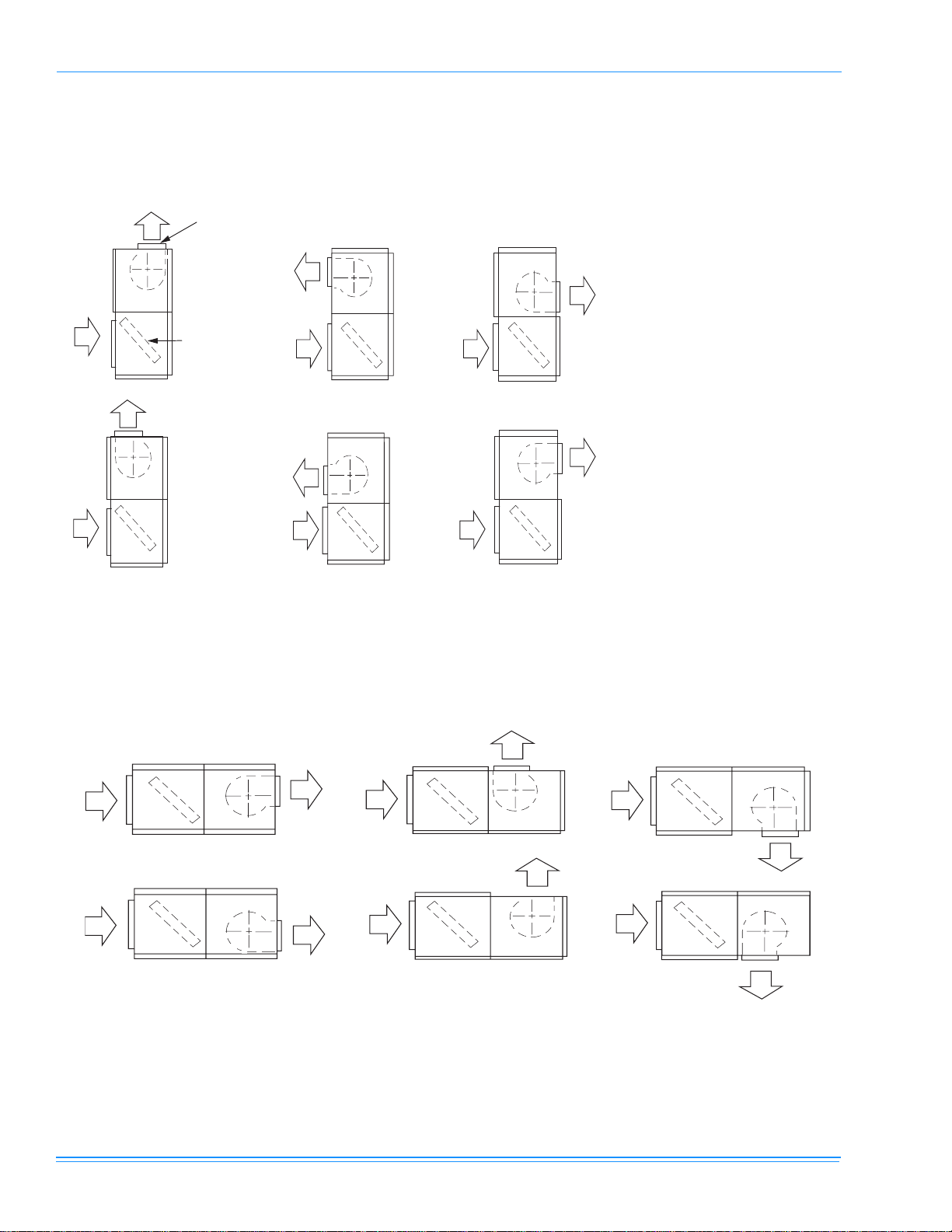
AIR DISCHARGE CONVERSION . . . . . . . . . . . . . . . . . . . . 6
AIR DISCHARGE . . . . . . . . . . . . . . . . . . . . . . . . . . . . . . . 6
UNIT INSTALLATION. . . . . . . . . . . . . . . . . . . . . . . . . . . . . . 9
LOCATION . . . . . . . . . . . . . . . . . . . . . . . . . . . . . . . . . . . . 9
RIGGING. . . . . . . . . . . . . . . . . . . . . . . . . . . . . . . . . . . . . . 9
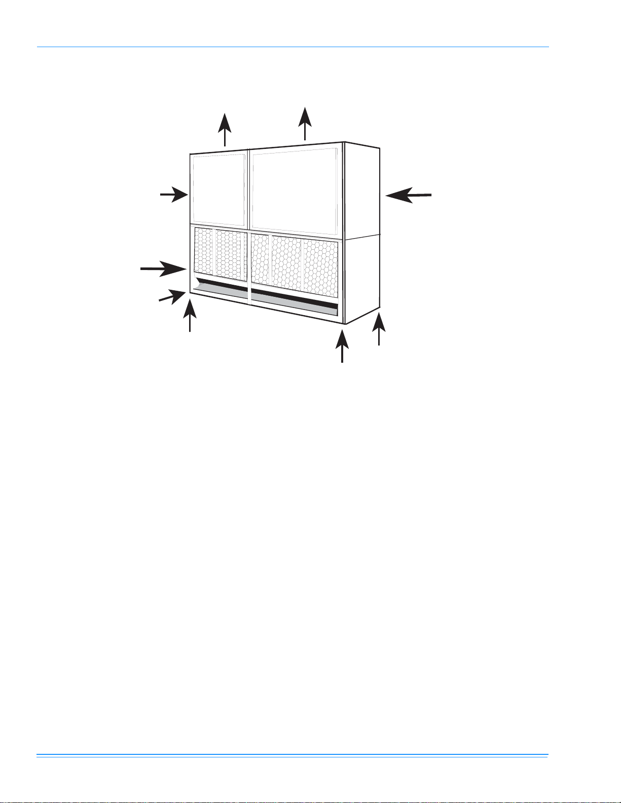
CLEARANCES . . . . . . . . . . . . . . . . . . . . . . . . . . . . . . . . . 9
MOUNTING. . . . . . . . . . . . . . . . . . . . . . . . . . . . . . . . . . . . 9
DUCT CONNECTIONS . . . . . . . . . . . . . . . . . . . . . . . . . . . 10
INSULATION. . . . . . . . . . . . . . . . . . . . . . . . . . . . . . . . . . 10
SUPPLY AIR DUCTS . . . . . . . . . . . . . . . . . . . . . . . . . . . 10
RETURN AIR DUCT ANGLES . . . . . . . . . . . . . . . . . . . . 11
DRAIN CONNECTIONS . . . . . . . . . . . . . . . . . . . . . . . . . 11
REFRIGERANT MAINS . . . . . . . . . . . . . . . . . . . . . . . . . . . 11
EVAPORATOR SECTION PIPING . . . . . . . . . . . . . . . . . 12
SUPPLY AIR BLOWER ADJUSTMENT. . . . . . . . . . . . . . . 12
ELECTRICAL CONNECTIONS . . . . . . . . . . . . . . . . . . . . . 14
INDOOR UNIT ELECTRICAL RATINGS . . . . . . . . . . . . . . 14
LIST OF FIGURES
Fig. Pg.
1 Product Nomenclature. . . . . . . . . . . . . . . . . . . . . . . . . 3
2 Factory Motor Mounting Position. . . . . . . . . . . . . . . . . 5
3 Typical Motor Mounting Assembly. . . . . . . . . . . . . . . . 5
4 Ll-15 Motor Arrangements. . . . . . . . . . . . . . . . . . . . . . 6
5 Ll-20 Motor Arrangements. . . . . . . . . . . . . . . . . . . . . . 7
6 Vertical Airflow Arrangements . . . . . . . . . . . . . . . . . . . 8
7 Horizontal Airflow Arrangements . . . . . . . . . . . . . . . . . 8
8 Horizontal Application Corner Weights . . . . . . . . . . . . 9
9 Vertical Application Corner Weights
(See Table On Page 9 For Weights) . . . . . . . . . . . . . 10
10 Suggested Method For Connecting Ductwork . . . . . . 11
11 Recommended Drain Piping . . . . . . . . . . . . . . . . . . . 11
12 Hole Locations For Pressure Drop Readings
(15 Ton) . . . . . . . . . . . . . . . . . . . . . . . . . . . . . . . . . . . 13
13 Hole Locations For Pressure Drop Readings
(20 Ton) . . . . . . . . . . . . . . . . . . . . . . . . . . . . . . . . . . . 14
14 Pressure Drop Across Indoor Coil (15 Ton). . . . . . . . 15
15 Pressure Drop Across Indoor Coil (20 Ton). . . . . . . . 15
16 15 Ton Blower Performance . . . . . . . . . . . . . . . . . . . 17
17 20 Ton Blower Performance . . . . . . . . . . . . . . . . . . . 17
18 Unit Dimensions Ll-15 And Ll-20 . . . . . . . . . . . . . . . . 18
19 Piping And Electrical Connection Locations . . . . . . . 19
LIST OF TABLES
Tbl. Pg.
1 Physical data . . . . . . . . . . . . . . . . . . . . . . . . . . . . . . . . 4
2 approximate rpm chart. . . . . . . . . . . . . . . . . . . . . . . . 14
3 LL-15 15 Ton AirFlow. . . . . . . . . . . . . . . . . . . . . . . . . 16
4 LL-20 20 Ton Airflow . . . . . . . . . . . . . . . . . . . . . . . . . 16
5 Unit Dimensions lL-15 and lL-20 . . . . . . . . . . . . . . . . 18
6 Piping And Electrical Connection Sizes. . . . . . . . . . . 19

66339-BIM-C-0206
Unitary Products Group 3
FIGURE 1 - Product Nomenclature
INDOOR SPLIT UPG PRODUCT NOMENCLATURE
LL -15 C 00 A T A AA 1 A
Model # Model Number
Description Options
L Product Category L = Air Handling Unit - Cooling F = Air Handling Unit - Heat Pump
F Product Identifier F = R-22 Standard Efficiency 2-Pipe
L = R-22 Standard Efficiency 4-Pipe
-15 Nominal Cooling
Capacity
MBH
-15 = 15 Ton
-20 = 20 Ton
CHeatType C = Cooling Only
00 Nominal Heating
Capacity 00 = No Heat Installed
A Airflow Options A = Standard Motor
TVoltage W = 460-3-60
S = 208/230-460-3-60 X = 575-3-60
A Factory Options A = None
AA Special Options AA = None
1 Generation 1 = First Generation 2 = Second Generation
A Product Style A = Style A B = Style B

66339-BIM-C-0206
4Unitary Products Group
GENERAL
The LL-15 and LL-20 evaporator units are designed for
use with the LL-15 and LL-20 Series condensing units.
Each unit consists of a coil section and a blower sec-
tion that are factory assembled and shipped. As shown
in arrangement 1 of figure 5, these sections may be
rearranged in the field for other air discharge patterns.
See figures 5, 6 and 7.
NOTES, CAUTIONS AND WARNINGS
Installer should pay particular attention to the words:
NOTE, CAUTION and WARNING. Notes are intended
to clarify or make installation easier. Cautions are given
to prevent equipment damage. Warnings are given to
alert installer that personal injury and/or equipment
damage may result if installation procedure is not han-
dled properly.
REPLACEMENT PARTS
Refer to parts manual for complete listing of replace-
ment parts on this equipment. The above forms and all
other forms referenced on this instruction may be
ordered from;
Standard Register
Telephone: 877-318-9675
Toll Free Fax: 877-379-7920
INSPECTION
As soon as a unit is received, it should be inspected for
possible damage during transit. If damage is evident,
the extent of the damage should be noted on the car-
rier’s freight bill. A separate request for inspection by
the carrier’s agent should be made in writing.
TABLE 1: PHYSICAL DATA
DESCRIPTION MODEL
LL-15 LL-20
EVAPORATOR COIL
Rows Deep X Rows High
Finned Length
Face Area, Feet
Tube (copper) OD, Inches
Fins (aluminum) per 1 inch
3 x 32
83
18.4
3/8
13
3 x 40
81
22.5
3/8
16
Piping Connections, Inches Liquid, Inches 5/8 5/8
Suction, Inches 1 1/8 1 3/8
CENTRIFUGAL BLOWERS (2
PER UNIT) Diameter X Width, Inches (Forward Curved) 15 X 12 18 X 18
FILTERS (THROWAWAY)
Size and Quantity Per Model,
Inches
16 X 25 X 2
20 X 20 X 2
20 X 24 X 2
20 X 25 X 2
25 X 25 X 2
-
4
-
4
-
-
-
-
10
-
Total Face Area, Feet 26.7 34.7
OPERATING CHARGE
(LBS 4-22) System 1
System 2 15.0
15.0 17.0
17.0
COMPONENT WEIGHT
Basic Unit (Less Motor & Drives)
Shipping Weight (lbs)
Operating Weight (lbs)
720
720
830
990
990
1115
Accessories
Hot Water Coil
Steam Coil
Supply Air Plenum
Return Air Grille
165
175
185
25
225
210
N/A
N/A
Blower Motor (1750 RPM)
(Field Installed) 120 (5 hp)
47 (3 hp) 120 (5 hp)

66339-BIM-C-0206
Unitary Products Group 5
LIMITATIONS
This unit must be installed in accordance with all
national and local safety codes. If no local codes apply,
installation must conform to the appropriate National
Code. The unit is designed to meet National Safety
Code Standards. If components are to be added to a
unit to meet local codes, they are to be installed at the
dealer’s and/or the customer’s expense.
BLOWER MOTOR MOUNTING LOCATIONS
Units are shipped from the factory less motor and
drives. The blower motor and drive packages are
ordered and shipped separately for field mounting.
MOTOR MOUNT ARRANGEMENTS
The motor mounting arrangement can be changed to
allow motor access based on the airflow arrangement
required. The recommended motor location for each
blower arrangement is as follows.
The units are shipped with the motor mount as shown
in figure 3.
If this is the desired position, the motor mounting
assembly is already in the correct position and the
motor and drive package can be installed without mod-
ifications.
FIGURE 2 - FACTORY MOTOR MOUNTING POSITION
MOTOR MOUNTING
CHANNELS ARE
ALWAYS SHIPPED
IN THIS LOCATION
FOR LL-20 UNITS
MOTOR MOUNTING
CHANNELS ARE
ALWAYS SHIPPED
IN THIS LOCATION
FOR LL-15 UNITS
FIGURE 3 - TYPICAL MOTOR MOUNTING ASSEMBLY

66339-BIM-C-0206
6Unitary Products Group
NOTE: The blower section must be lifted off the evap-
orator section to gain access to the mounting
channel fasteners. Since these sections have
to be repositioned for the arrangements 2
through 10 and 12 of figures 4 and 5, the
motor mounting assembly should be relocated
before the two sections are rejoined.
AIR DISCHARGE CONVERSION
AIR DISCHARGE
The units are shipped for upflow operation, but may be
converted for any of the illustrated air discharge pat-
terns shown in figures 5 and 6. Convert as follows:
1. Remove the panels from the blower section.
2. Remove the Phillips machine screws located inside
casing corner angles that hold the coil and blower
sections together.
3. Rotate the blower section for the desired air dis-
charge pattern.
NOTE: Before proceeding to step 4, see the section
on the blower motor mounting locations and
mount the blower motor in the desired position.
4. If accessory heating coils are used, mount heating
coil between cooling coil and blower sections.
Screw fastening locations are the same for all sec-
tions and heating accessories. If heating coils are
not used, fasten coil section to blower section with
machine screws removed in step 2.
5. Before replacing panels, see duct connections and
drain connections.
6. Replace panels.
FIGURE 4 - LL-15 MOTOR ARRANGEMENTS

66339-BIM-C-0206
Unitary Products Group 7
FIGURE 5 - LL-20 MOTOR ARRANGEMENTS
ARRANGEMENT 1, 4, 8, OR 11
ARRANGEMENT 3, 5 OR 10
ARRANGEMENT 2, 6 OR 7
NOTE: Since the motor mounting assembly can-
not be secured to the panel with the
blower openings, the motor cannot be
installed in any of the normally recom-
mended bottom positions.
ARRANGEMENT 9 OR 12

66339-BIM-C-0206
8Unitary Products Group
FIGURE 6 - VERTICAL AIRFLOW ARRANGEMENTS
AIR
AIR
BLOWER
1
EVAPORATOR
COIL AIR
AIR
2
AIR
AIR
AIR
AIR
4
AIR
AIR
5
AIR
AIR
6
3
* IF REQUIRED, SOME AIR CAN
BE BROUGHT THROUGH THE
BOTTOM OF THE EVAPORATO
R
SECTION.
**
*
**
*
FIGURE 7 - HORIZONTAL AIRFLOW ARRANGEMENTS
AIR
AIR
AIR
AIR
AIR
AIR
AIR
AIR
AIR
AIR
AIR
AIR
78 9
11 12
10

66339-BIM-C-0206
Unitary Products Group 9
UNIT INSTALLATION
LOCATION
The evaporator blowers are not designed for outdoor
installation. They must be located inside the building
structure, either inside or outside the conditioned
space where they are protected from rain and other
such moisture.
The unit should be located as close to the condensing
unit as practical and positioned to minimize bends in
the refrigerant piping.
Units being installed vertically or horizontally can be set
directly on a floor or platform, or supported by metal or
wooden beams.
Units being installed horizontally can be suspended
from above. Refer to the installation instructions of the
appropriate horizontal suspension kit.
RIGGING
Care must be taken when moving the unit. Do not
remove any packaging until the unit is near the place of
installation. SPREADER BARS SHOULD BE USED
BETWEEN THE SLINGS TO PREVENT CRUSHING
THE UNIT FRAME OR PANELS.
When preparing to move the unit, always determine the
center of gravity of the unit in order to equally distribute
the weight. Rig the unit by attaching chain or cable
slings around the bottom skid. A lift truck may be used
to raise a unit to a suspended location. Refer to table 2
for the total unit operating weight.
CLEARANCES
A 25-inch clearance is required on the end with the pip-
ing connections and the supply air blower motor to
properly service and maintain the unit and to replace
the filters.
Some clearance will also be required for the duct and
power wire connections. A clearance equal to the unit
width is required on one end of the unit if the blower
shaft or evaporator coil is to be replaced without mov-
ing the unit.
MOUNTING
The evaporator blower may be suspended from the
joists with isolation type hangers or hooks. A suspen-
sion accessory, which includes three suspension chan-
nels and hardware, may be ordered separately. The
corner weights for each unit are shown on pages 9 and
10.
Unit Size Position Shipping
Weight Operating
Weight ABCD Unit
Length Unit
Width
15 Ton Indoor Horizontal 720 830 155 187 207 171 89.5 59
15 Ton Indoor Vertical 720 830 172 194 188 166 89.5 29.5
20 Ton Indoor Horizontal 990 1115 230 345 249 166 100 74
20 Ton Indoor Vertical 990 1115 263 238 232 256 100 36.5
FIGURE 8 - HORIZONTAL APPLICATION CORNER WEIGHTS
DC
20 Ton Motor Location
Return Air
A
B
Horizontal Application Corner Weights
15 Ton Motor Location
Supply Air

66339-BIM-C-0206
10 Unitary Products Group
DUCT CONNECTIONS
Ductwork should always be suspended with hangers or
supported by legs. It should never be fastened directly
to the building structure.
Allow clearance around ducts for safety in the handling
of heated air and for insulation when required.
INSULATION
Ductwork insulation should meet the following criteria:
1. Be used when ducts pass through an uncondi-
tioned space in the cooling season or through an
unheated space during the heating season.
2. Include a vapor barrier around the outside to pre-
vent the absorption of moisture.
3. Be no less than 2 inches thick with the weather-
proof coating when applied to ducts exposed to
outdoor conditions.
SUPPLY AIR DUCTS
See figure 8 for suggested method of connecting sup-
ply air ductwork. Non-flammable material collars
should be used to minimize the transmission of noise
and/or vibration.
FIGURE 9 - VERTICAL APPLICATION CORNER WEIGHTS
(See Table on page 9 for Weights)
Supply Air
15 Ton
Motor Location
20 Ton Motor
Location
Return Air
A
B
C
D
(Rear Corner)

66339-BIM-C-0206
Unitary Products Group 11
RETURN AIR DUCT ANGLES
Return air duct angles are shipped turned in. They are
intended to be unscrewed and turned for connection of
ductwork.
DRAIN CONNECTIONS
All drain lines MUST be trapped and located so they
will not be exposed to freezing temperatures.
The LL-20 evaporator blower has 7/8” OD steel con-
densate stub at each end of a single drain pan. Both
ends are closed with plastic caps. A plastic ell (field
supplied) can be used. Attach the ell to the desired end
and run a full size 7/8” drain line to the nearest drain
facility. Seal the cap at the unused end with suitable
mastic. The LL-15 evaporator has one 7/8” OD drain
connection through the right side of the cabinet.
Drain piping should be constructed as shown in figure
9. The 5-inch dimension is intended to exceed the neg-
ative static pressure developed by the supply air blow-
ers. If it does not, the condensate will not drain properly
and may overflow the drain pan. The trap must be at
least 2 1/2 inches deep to maintain a water seal under
all operating conditions, especially when the blowers
are starting.
REFRIGERANT MAINS
Hard drawn copper tubing should be used where no
appreciable amount of bending around pipes or other
obstructions is necessary. Use long radius ells wher-
ever possible. If soft copper is used, care should be
taken to avoid sharp bends that may cause a restric-
tion.
FIGURE 10 - SUGGESTED METHOD FOR CONNECTING DUCTWORK
24"
AIR
OUTLET
BLOWER
GASKETS
(
BY INSTALLER
)
FLANGED DUCT
CONNECTION
(FIELD
FABRICATED)
NON-FLAMMABLE
COLLAR
DUCT
TRANSITION
DUCT
FIGURE 11 - RECOMMENDED DRAIN PIPING

66339-BIM-C-0206
12 Unitary Products Group
Where refrigerant lines pass through a wall, pack fiber-
glass insulation and a sealing material such as perma-
gum around the refrigerant lines to reduce vibration
and to retain some flexibility in the lines.
Suitable hangers, brackets or clamps should support
the refrigerant lines.
Braze all copper-to-copper joints with Silfos-5 or equiv-
alent brazing material. Do not use soft solder.
Never braze or solder the liquid and suction lines
together.
The complete suction line should be insulated with no
less than ½” Armaflex or equivalent.
If it is desirable to tape or wire the liquid and suction
lines together for support purposes, they must be com-
pletely insulated from each other.
EVAPORATOR SECTION PIPING
The units are shipped with a holding charge of nitro-
gen. The connections are terminated with a copper
disc brazed over the ends.
Before starting installation of the mains, be sure the
unit has not developed a leak in transit by connecting a
pressure gauge to the service access port. If pressure
still exits, the circuit may be considered leak free. If
pressure does not exist, the unit must be evacuated
along with the field installed refrigerant piping.
NOTE: To minimize the possibility of system failure
due to dirt and moisture, a filter-drier must be
installed in each liquid line as close to the
evaporator as possible. Filter-driers are not
supplied with the unit.
The temperature required to make or break a brazed
joint is sufficiently high to cause oxidation of the copper
unless an inert atmosphere is provided.
The liquid, suction and drain connections inside the
unit must be piped to the outside. Refer to figure 18 for
unit dimensions or the locations and the dimensions of
the access openings in the unit panel.
Depressurize the system and remove any caps or
discs on the liquid and suction connections that will not
permit a free flow of nitrogen.
Connect a supply of dry nitrogen through a reducing
regulator to an access valve or charging tail. Choose a
procedure that will allow nitrogen to flow continuously
through the system and reach all joints to be brazed.
Begin the refrigerant main piping by installing the liquid
line from the condensing unit to the evaporator liquid
connection, maintaining a flow of nitrogen during all
brazing operations. The filter drier and sight glass must
be located in this line, close to the evaporator. Make
the suction line connection at the evaporator and run
the line to the condensing unit.
After evacuating the holding charge and puncturing the
sealing caps with a small drill bit, unbraze the condens-
ing unit suction disc and connect the line. Maintain a
flow of nitrogen through the liquid line to the evapora-
tor, through the evaporator, back to the condensing
unit and out the suction connection and service port.
NOTE: Size the suction line outside the evaporator
casing per the line sizing information provided
in the appropriate condensing unit installation
instruction.
The bulbs for the thermal expansion valve on the
blower units are not factory-installed in their final loca-
tion; they are only temporarily taped for shipment. The
bulb for system one must be fastened in the 4 o’clock
or 8 o’clock position to the system one suction line of
system one leaving the evaporator coil after piping con-
nections are made. Repeat the procedure for system
two, locating the bulb in the 4 o’clock or 8 o’clock posi-
tion to the system two suction line. Use the bulb clamps
from the bag taped to the suction connection inside the
blower unit.
NOTE: Ensure the TXV bulbs are not crossed
between systems. Undesirable performance
and possible compressor damage may occur.
SUPPLY AIR BLOWER ADJUSTMENT
The RPM of the supply air blower will depend on the
required CFM and the external static pressure (both
inlet and outlet) imposed on the unit. If the external
static pressure at the required CFM has been calcu-
lated for the ductwork, the blower RPM and blower
driver kit/motor can then be obtained from the air flow
table.
Once the RPM and motor/kit combination is known, the
number of turns open for the adjustable sheave can be
estimated from Table 3.

66339-BIM-C-0206
Unitary Products Group 13
Each unit has a low static and a high static option. The
15 Ton unit offers a 3 hp motor and sheave combina-
tion for the low static option and a 5 hp motor and
sheave combination for the high static option. The 20
Ton offers a 5 hp motor to be used with either the low
or high static sheaves.
Each motor pulley has:
1. A threaded barrel with two flats (or notched
recesses 180º apart).
2. A movable flange with one set screw.
After the movable flange has been rotated to the
proper number of turns open, the set screw should be
tightened against the flat on the barrel to lock the mov-
able flange in place. If the pulley includes a locking col-
lar, the locking collar must be loosened to adjust the
setting of the movable flange.
Note the following:
1. The supply of air CFM must be within the limita-
tions shown in the tables. Be sure not to over amp
the motor.
2. All pulleys can be adjusted in 1/2 turn increments.
3. The tension on the belt(s) should be adjusted for a
deflection of 3/16” per foot of belt span with an
applied force of 2 to 3 pounds.
Once the supply air blower motor is operating, adjust
the resistances in both the supply and the return duct
system to balance the air distribution throughout the
conditioned space. The job specification may require
that the balancing be done by someone other than the
equipment installer.
To check the supply air CFM after the initial balancing
has been completed:
1. Drill two 5/16” holes in the side panel as shown in
figure 10 for the 15 Ton or figure 11 for the 20 Ton.
2. Insert at least 6” of 1/4” tubing into each of these
holes for sufficient penetration into the air flow on
either side of the indoor coil.
NOTE: The tubes must be inserted and held in a posi-
tion perpendicular to the air flow so that veloc-
ity pressure will not affect the static pressure
reading.
3. Using an inclined manometer, determine the pres-
sure drop across a dry coil.
4. Consult the appropriate coil pressure drop chart to
determine the CFM.
5. After the readings have been obtained, remove the
tubes and seal up the drilled holes in the side
panel. Dot plugs (P/N 029-13880-000) are avail-
able through Source One parts.
FIGURE 12 - HOLE LOCATIONS FOR PRESSURE
DROP READINGS (15 TON)
5/16"
HOLE
5/16"
HOLE
18"
7"
22"
10"
EVAPORATOR
COIL
FILTERS
COIL SECTION

66339-BIM-C-0206
14 Unitary Products Group
ELECTRICAL CONNECTIONS
Refer to matching condensing section wiring diagrams.
Provide a disconnect switch and fusing as required.
Follow all applicable local and national codes.
Install interconnecting control wiring between condens-
ing section, evaporator blower and room thermostat.
NOTE: Motors are wired for a 460 V power supply.
Refer to the wiring diagram inside the motor
terminal box when utilizing a 208 V or 230 V
power supply. LL-20 units require field
mounting of the blower motor. Wiring for
the motor is field supplied.
INDOOR UNIT ELECTRICAL RATINGS
FIGURE 13 - HOLE LOCATIONS FOR PRESSURE
DROP READINGS (20 TON)
Approximate RPM Chart
Turns Open LL-15 LL-20
Low Static
Drive Kit Hi Static
Drive Kit Low Static
Drive Kit Hi Static
Drive Kit
5 650 840 580 700
4 675 875 605 730
3 705 910 635 750
2 730 945 660 780
1 750 980 685 805
0 800 1005 715 835
TABLE 2: APPROXIMATE RPM CHART
5/16"
HOLE
5/16"
HOLE
"
7"
25"
14"
EVAPORATOR
COIL
FILTERS
COIL SECTION
22
Model
Number Blower
Motor HP Power
Supply FLA Minimum
Circuit
Ampacity
Max.
Fuse
Size1
1. Maximum fuse or maximum circuit breaker (HACR type
per NEC).
LL-15
3208-3-60 10.6 13.3 20
230-3-60 9.6 12.0 20
5208-3-60 17.5 21.9 35
230-3-60 16.7 20.9 35
3460-3-60 4.8 6.0 15
575-3-60 3.6 4.5 15
5460-3-60 7.6 9.5 15
575-3-60 5.2 6.5 15
LL-20 5
208-3-60 17.5 21.9 35
230-3-60 16.7 20.9 35
460-3-60 7.6 9.5 15
575-3-60 5.2 6.5 15

66339-BIM-C-0206
Unitary Products Group 15
FIGURE 14 - PRESSURE DROP ACROSS INDOOR COIL (15 TON)
Pressure Drop Across Indoor Coil 15 Ton
0
0.05
0.1
0.15
0.2
0.25
0.3
0.35
0.4
0.45
0.5
4000 5000 6000 7000 8000
CFM
I.W.C.
FIGURE 15 - PRESSURE DROP ACROSS INDOOR COIL (20 TON)
Pressure Drop Across Indoor Coil 20 Ton
0
0.1
0.2
0.3
0.4
0.5
0.6
5000 6000 7000 8000 9000 10000
CFM
IWC over coil

66339-BIM-C-0206
16 Unitary Products Group
Note: Airflow tables based on 2” filters, dry evaporator coil.
TABLE 3: LL-15 15 TON AIRFLOW
0.4 ESP 0.6 ESP 0.8 ESP 1 ESP 1.2 ESP 1.4 ESP
CFM RPM BHP kW RPM BHP kW RPM BHP kW RPM BHP kW RPM BHP kW RPM BHP kW
4400 660 1.5 1.43 725 1.8 1.69 756 2.0 1.86 886 2.4 2.29 928 2.6 2.4
4600 663 1.6 1.46 733 1.9 1.77 775 2.1 1.99 891 2.6 2.4 937 2.8 2.59
4800 667 1.6 1.5 741 2.0 1.85 794 2.3 2.12 897 2.7 2.52 946 3.0 2.78
5000 671 1.7 1.55 749 2.1 1.94 811 2.4 2.26 903 2.8 2.64 955 3.2 2.98
5200 676 1.7 1.61 758 2.2 2.03 828 2.6 2.39 910 3.0 2.77 963 3.4 3.17
5400 682 1.8 1.68 767 2.3 2.13 844 2.7 2.54 917 3.1 2.91 972 3.6 3.36
5600 688 1.9 1.76 776 2.4 2.24 859 2.9 2.68 924 3.3 3.05 981 3.8 3.56
5800 696 2.0 1.85 785 2.5 2.36 873 3.0 2.83 931 3.4 3.2 990 4.0 3.75
6000 647 1.9 1.78 704 2.1 1.95 794 2.7 2.48 885 3.2 2.98 938 3.6 3.36 998 4.2 3.94
6200 654 2.0 1.83 712 2.2 2.06 804 2.8 2.61 897 3.4 3.14 946 3.8 3.53 1007 4.4 4.14
6400 662 2.0 1.89 722 2.3 2.18 814 2.9 2.74 909 3.5 3.29 954 4.0 3.7
6600 670 2.1 1.97 732 2.5 2.31 824 3.1 2.89 919 3.7 3.45 963 4.1 3.88
6800 679 2.2 2.06 742 2.6 2.45 834 3.2 3.03 928 3.9 3.62 971 4.4 4.07
7000 688 2.3 2.17 754 2.8 2.6 844 3.4 3.19 936 4.1 3.79 980 4.6 4.27
7200 698 2.5 2.3 766 3.0 2.77 855 3.6 3.35 944 4.2 3.96 990 4.8 4.47
7400 708 2.6 2.45 779 3.1 2.94 866 3.8 3.52 950 4.4 4.13 999 5.0 4.68
7600 719 2.8 2.61 792 3.3 3.12 877 4.0 3.7 956 4.6 4.31
7800 730 3.0 2.78 807 3.5 3.31 888 4.1 3.88 960 4.8 4.49
Denotes use of 5 hp motor with high static pulley kit.
TABLE 4: LL-20 20 TON AIRFLOW
0.4 ESP 0.6 ESP 0.8 ESP 1 ESP 1.2 ESP 1.4 ESP
CFM RPM BHP kW RPM BHP kW RPM BHP kW RPM BHP kW RPM BHP kW RPM BHP kW
6000 612 2.0 1.77 681 2.5 2.24 720 2.7 2.44 763 3.1 2.71
6200 617 2.1 1.87 684 2.6 2.32 724 2.9 2.53 767 3.2 2.82
6400 623 2.2 1.97 688 2.7 2.40 727 3.0 2.63 771 3.3 2.94
6600 629 2.3 2.07 692 2.8 2.48 731 3.1 2.73 776 3.4 3.06
6800 634 2.4 2.17 695 2.9 2.57 735 3.2 2.83 781 3.6 3.19
7000 640 2.6 2.27 699 3.0 2.66 739 3.3 2.94 786 3.7 3.32
7200 646 2.7 2.38 703 3.1 2.75 744 3.4 3.05 791 3.9 3.46
7400 582 2.0 1.74 651 2.8 2.48 707 3.2 2.85 748 3.6 3.16 797 4.1 3.61
7600 590 2.1 1.87 657 2.9 2.59 711 3.3 2.95 753 3.7 3.28 803 4.2 3.76
7800 597 2.3 2.00 662 3.0 2.69 715 3.4 3.05 757 3.8 3.40 809 4.4 3.92
8000 603 2.4 2.13 667 3.2 2.80 719 3.6 3.16 762 4.0 3.52 816 4.6 4.08
8200 610 2.5 2.26 673 3.3 2.91 723 3.7 3.26 767 4.1 3.65
8400 617 2.7 2.40 678 3.4 3.02 727 3.8 3.38 772 4.3 3.79
8600 624 2.8 2.53 683 3.5 3.13 731 3.9 3.49 777 4.4 3.92
8800 630 3.0 2.66 689 3.6 3.24 735 4.1 3.61 783 4.6 4.06
9000 637 3.1 2.79 694 3.8 3.35 740 4.2 3.73 788 4.7 4.21
9200 577 2.0 1.80 643 3.3 2.92 699 3.9 3.46 744 4.3 3.85 794 4.9 4.36
9400 584 2.3 2.08 649 3.4 3.06 704 4.0 3.57 748 4.5 3.98 800 5.1 4.51
9600 591 2.6 2.34 655 3.6 3.19 709 4.1 3.68 753 4.6 4.11 806 5.3 4.67
9800 598 2.9 2.59 661 3.7 3.32 714 4.3 3.80 757 4.8 4.25 812 5.4 4.83
10000 605 3.2 2.81 667 3.9 3.46 719 4.4 3.91
Denotes use of high static pulley option.

66339-BIM-C-0206
Unitary Products Group 17
FIGURE 16 - 15 TON BLOWER PERFORMANCE
15 TON BLOWER PERFORMANCE
0.4
0.6
0.8
1
1.2
1.4
1.6
4200 4700 5200 5700 6200 6700 7200 7700
CFM
ESP
FIGURE 17 - 20 TON BLOWER PERFORMANCE
20 TON BLOWER PERFORMANCE
0.4
0.6
0.8
1
1.2
1.4
1.6
6000 6500 7000 7500 8000 8500 9000 9500 10000
CFM
ESP

66339-BIM-C-0206
18 Unitary Products Group
FIGURE 18 - UNIT DIMENSIONS LL-15 and LL-20
TABLE 5: UNIT DIMENSIONS LL-15 AND LL-20
MODELABCDEFGH J K L M
LL-15 89-1/2 85.0 26.0 29-1/2 59 1-7/16 15-7/8 12-7/16 15-13/16 16 16 20-3/4
LL-20 100-1/8 95-5/8 33-1/4 36-5/8 73-1/4 2-1/2 18-7/8 16-1/2 15-13/16 21-7/8 18 22-9/16

66339-BIM-C-0206
Unitary Products Group 19
FIGURE 19 - PIPING and ELECTRICAL CONNECTION LOCATIONS

Subject to change without notice. Printed in U.S.A. 66339-BIM-C-0206
Copyright © 2006 by Unitary Products Group. All rights reserved. Supersedes: 66339-BIM-B-0304/035-18503-001-B-0304
Unitary 5005 Norman
Products York OK
Group Drive 73069
This manual suits for next models
1
Table of contents
Other Unitary products group Blower manuals