United Technologies interlogix TruVision TVB-2402 User manual

TruVision High
Definition TVI
Bullet Camera Installation
Guide
TVB
-2402/TVB-4402
TVB-2404/TVB-4404
P/N 1072938-EN • REV A • ISS 10MAR15


2 Installation Guide
Product overview
This is the TruVision High Definition TVI Bullet
Camera Installation Guide for models TVB-
2402/TVB-4402 and TVB-2404/TVB-2404. This
guide describes a standard installation.
Package contents:
Camera with power
and video output
cables
4 screws and 4
anchors for wall or
ceiling installation
Back box
Screws M4.8 ×18,
4pcs to attach the
back box

Installation Guide 3
Template
Hex wrench
•WEEE and Battery
Disposal
CD
Ceiling Mounting
11
11
2
22
2
1:Screw Hole for
Bracket
2:Screw Hole for
Mounting Base

4 Installation Guide
Camera description
1. CVBS output cable
(black)
2. TVI output cable
(grey)
3. Power cable
4. Camera body
5. Sun shield
6. Lens cover
7. Mounting bracket
8. Back box
Note:
Please check the camera output settings before
setting up a system. The TVI video output can be
only connected to DVR with TVI signal input. The
8
2
7
3
1
5
6
4

Installation Guide 5
CVBS output supports the standard monitor, test
monitor, encoder and DVR.
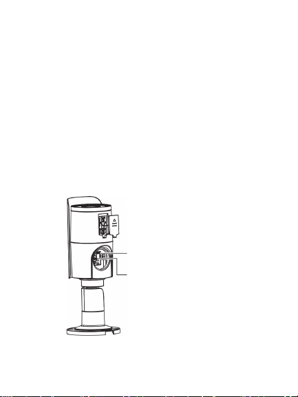
For TVB-2402 / TVB-4402, the CVBS and TVI
output can not be performed at the same time, you
can use the built-in DIP switch to select the camera
video output.
For TVB-2404/TVB-4404, the built-in DIP switch is
used to enable/disable WDR feature, when WDR
feature is enabled, the CVBS output will be blocked
out.
DIP switch
Menu button

6 Installation Guide
Installation
To install the camera:
1. Using the template, place it level against the
mounting surface and mark the position of the
mounting holes.
2. Following all local codes, drill and prepare the
mounting holes.
3. (Optional) Install the back box on the wall.
Ceiling Mounting
11
11
2
22
2
1:Screw Hole for
Bracket
2:Screw Hole for
Mounting Base

Installation Guide 7
4. Route the cables to the cable hole and connect
the corresponding cables. Using a 75-ohm
coaxial video cable, connect the camera TVI
video output and a TVI DVR, and connect a
12 VDC or 24 VAC power supply to the power
cable.
5. Secure the camera to the ceiling or wall with
the screws.

8 Installation Guide
6. Loosen the three screws and adjust the camera
according to the figure below to get an optimum
angle. Tighten the screw after completing the
adjustment.

Installation Guide 9
7. Loosen the three screws and adjust the camera
according to the figure below to get an optimum
angle. Tighten the screw after completing the
adjustment.
Programming
Programming on TVI output:
Once the camera hardware has been installed, you
can configure the camera settings on the TVI DVR.
360°
90°
360°

10 Installation Guide
Select PTZ protocol as TruVision Coax and click
menu button to call up the camera menu.
For more details, please see the TVI DVR user
manual.
Programming on CVBS output:
The camera can then be configured by using the
built-in OSD button or a TVS-C200 controller
(purchase separately).
Please connect a monitor and the TVS-C200 (if
needed) controller as following system figure.
TVI

Installation Guide 11
TVB-2402/TVB-4402
The camera has CVBS and TVI selectable video
output. Set the built-in DIP switch to CVBS for
viewing the program on a standard monitor.
The TVI is blocked out until you finish the settings
and change the DIP switch back to TVI.
TVB-2404/TVB-4404
The camera has the CVBS and TVI dual video
output. The built-in DIP switch is for WDR/CVBS
selection.
TVI
CVBS

12 Installation Guide
Please set the built-in DIP switch to CVBS for
viewing the program on a standard monitor.
When the programing is finished, you may change
the DIP to WDR to enable the WDR feature. In such
case, the CVBS output will be blocked out.
If the DIP is set as CVBS, the WDR feature will be
disabled, and the camera has CVBS and TVI output
available at the same time

Installation Guide 13
Setup menus
TVB-2402/TVB-4402

14 Installation Guide
TVB-2404/TVB-4404

Installation Guide 15
Specifications
Power supply
12 VDC / 24 VAC
Current
TVB-2402 / TVB-4402:
12 VDC: Max. 333 mA
24 VAC: Max. 250 mA
TVB-2404/TVB-4404:
12 VDC: Max. 420 mA
24 VAC: Max. 250 mA
Power
consumption
TVB-2402/TVB-4402:
12 VDC: Max. 4W
24 VAC: Max. 6W
TVB-2404/TVB-4404:
12 VDC: Max. 5W
24 VAC: Max. 6W
Weight (net)
860 g / 1.89 lb. (without back box)
1075 g / 2.36 lb. (with back box)
Dimensions
105 × 94.7 × 265.4 mm / 4.13 ×
3.74 × 10.4 in. (without back box)
105 × 94.7 × 301.4 mm / 4.13 × 3.74
× 11.86 in. (with back box)

16 Installation Guide
Legal and regulatory
information
Copyright:
© 2015 United Technologies Corporation,
Interlogix is part of UTC Building & Industrial Systems, a unit of
United Technologies Corporation. All rights reserved.
Trademarks and patents:
Trade names used in this document may be trademarks or
registered trademarks of the manufacturers or vendors of the
respective products.
Manufacturer:
Interlogix
2955 Red Hill Avenue, Costa Mesa, CA 92626-5923, USA
Authorized EU manufacturing representative:
UTC Fire & Security B.V.
Kelvinstraat 7, 6003 DH Weert, The Netherlands
Certification:
N4131
FCC compliance: Class A
Class A: This equipment has been tested and found to comply with
the limits for a Class A digital device, pursuant to part 15 of the
FCC Rules. These limits are designed to provide reasonable
protection against harmful interference when the equipment is
op
erated in a commercial environment. This equipment generates,
uses, and can radiate radio frequency energy and, if not installed
and used in accordance with the instruction manual, may cause

Installation Guide 17
harmful interference to radio communications. Operation of this
equipment in a residential area is likely to cause harmful
interference in which case the user will be required to correct the
interference at his own expense.
ACMA compliance
Notice! This is a Class A product. In a domestic environment this
product may cause radio interference in which case the user may
be required to take adequate measures.
Canada
This Class A digital apparatus complies with Canadian ICES-003.
Cet appareil numérique de la classe A est conforme à la norme
NMB-0330 du Canada.
European Union directives:
12004/108/CE (EMC directive): Hereby, UTC Fire & Security declares
that this device is in compliance with the essential requirements and
other relevant provisions of Directive 2004/108/EC.
2012/19/EU (WEEE directive): Products marked
with this symbol cannot be disposed of as
unsorted municipal waste in the European Union.
For proper recycling, return this product to your
local supplier upon the purchase of equivalent new
equipment, or dispose of it at designated collection
points. For more information see:
www.recyclethis.info.
Contact information:
For contact information, see www.interlogix.com or
www.utcfssecurityproducts.eu

This manual suits for next models
3
Table of contents
Other United Technologies Security Camera manuals
Popular Security Camera manuals by other brands

Toshiba
Toshiba IK-TF9C Specifications

Moog Videolarm
Moog Videolarm IRHW75CF2N Installation and operation instructions

Samsung
Samsung SCC-641 - 22x Zoom Smart Dome Camera Specification sheet

Dahua
Dahua DH-SD6323E-H installation manual

Risco
Risco VUpoint RVCM52P13 quick guide

TKH security
TKH security Siqura EX-PD24 installation manual