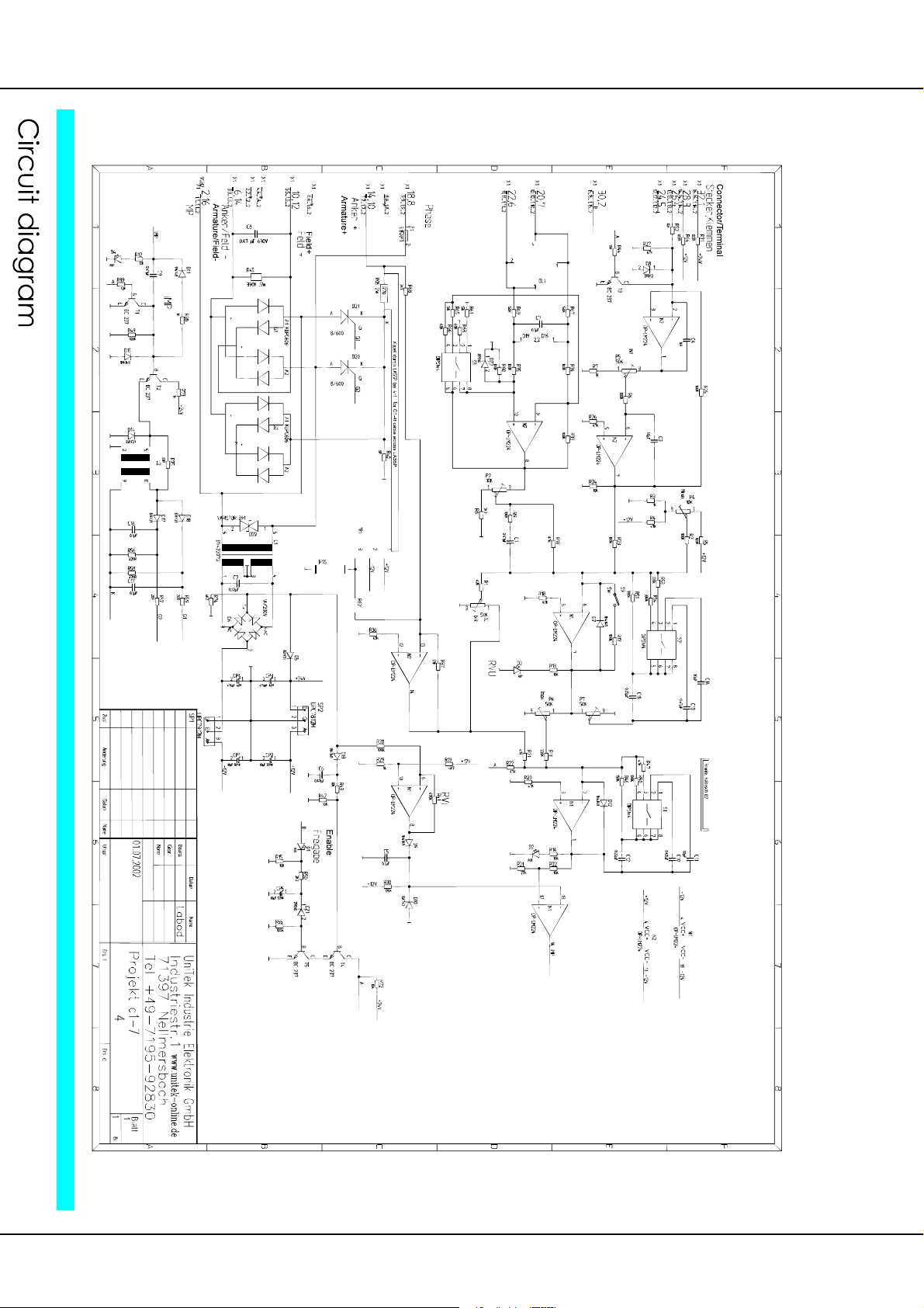
Classic C1 230/180 - 4 (f)
4
Thyristor Drive
- for inductive and ohmic consumer loads’
Applications
- speed control of dc motors
- 1-quadrant operation, driving
- power: up to 720W
- tacho control
- armature voltage control with IxR compensation
- torque control
- cascade control speed/current
- rectangular current/speed characteristic curve
- switch on and switch off logic
- mains connection can directly be switched
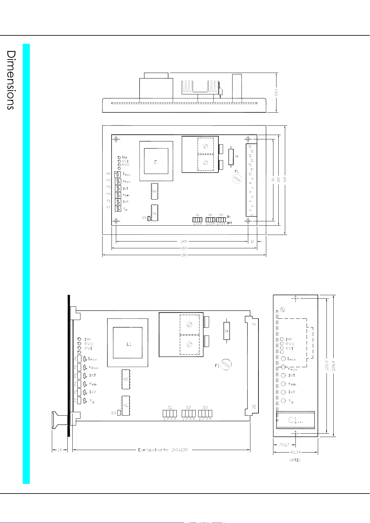
Compact single-board device
- European format
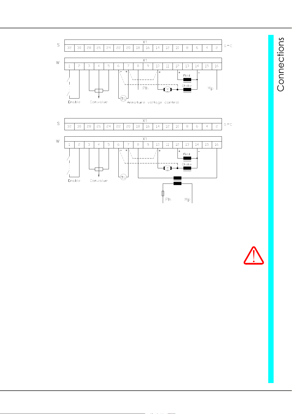
- pluggable terminal connection (-W)
- C1: galvanic connection
- C1-4f: galvanic isolation of the control and the power section
- fully insulated power semi-conductor
- field rectifier
Note for C1 devices:
Direct mains connection
- zero connection >> on thyristor negative electrode potential
- all control connections >> on mains potential
- switches and poti >> isolation voltage > 1500V
Connection via an isolating transformer
- zero connection >> with potential isolation
- control connections >> to be earthed and shielded
Note for C1-4f devices:
Tacho control
- device >> with potential isolation
Armature voltage control
- control unit >> with a high impedance mains connection
- zero connection (terminal no. 5) must not be earthed
Build
- switch cabinet mounting according to the VDE, DIN and EU regulations
- standard control electronics REG
- intrinsically safe power section with current control loop
- optional units
Galvanic isolation between
- the power section and the housing
- the power section and the control electronics
The distance of air gaps and leakage paths adhere to the VDE standards (>8mm).
Components
- fully insulated thyristor modules, comfortably over-dimensioned
- only components customary in trade and industrially standardised are used
- high-quality bases for the IC with external connections
- LED displays
- DIP switches for the P-I adjustment of the current control loop
- precision potentiometers for fine adjustments
- plug-in jumpers for the system set-up