unitrode EV2014 User manual

Contents
Section Page No.
Introduction 1
EV2014 Functional Description 1
EV2014 Contents 2
EV2014 Connections 2
EV2014 Configuration 2
Installing the User Interface Program 3
Using the EV2014 Program 3
Main Menu 3
Monitor Screen 4
Digital Magnitude Filter Menu 6
Data Logging 6
Display Program Menu 7
Measure VOS Screen 8
Appendix A: AP14 User's Guide 9
Appendix B: Troubleshooting 10
Appendix C: EV2014 Schematic 11
Introduction
The bq2014 Gas Gauge IC provides battery capacity
monitoring in a single 16-pin SOIC or DIP package. The
EV2014 Evaluation Board provides a useful means to
test bq2014 functionality and easily interface with the
device over the RS-232 port of a PC. The bq2014 fea-
tures:
nBattery capacity monitoring functions
nLED display of available charge
nDQ serial I/O port communications functions
Functional Description
The EV2014 provides functional evaluation of the
bq2014 IC on a PCB. The actual implementation of a
bq2014-based design will be significantly smaller in size.
See the bq2014 data sheet (Dec. 1994 B or later) for
bq2014 specifications.
Power Source
The bq2014 derives its VCC from either an external
source or from the battery connected to the BAT+ (J1)
and BAT- (J2) terminal blocks. Refer to Table 4 in Using
the bq2010-—A Tutorial for Gas Gauging for the proper
size of R17 as part of the VCC regulation. The EV2014
Evaluation Board is shipped with a 200KΩresistor for
R17.
Current Path
The bq2014 uses a sense resistor (R16) on the negative
terminal of the battery to measure charge and discharge
activity. This resistor may be changed if necessary. The
system load is connected between the BAT+ (J1) and
PACK-(J2) terminal blocks (see the schematic in Appen-
dix C).
Parameter Programming
The EV2014 is programmed by the segment program-
ming pins, using jumpers PROG1-PROG6. The pro-
gramming pins determine:
nProgrammed full count
nScale factor
1
EV2014
Gas Gauge Evaluation Board
10/97 Rev. B Board

nSelf-discharge rate
nDisplay mode
EV2014 Contents
Each package contains the following items:
1 EV2014 PC Board
This includes the bq2014 sample, current regula-
tors, programming jumpers, battery divider resis-
tors, and the PC serial port interface.
1 EV2014 DQ/RS-232 Cable
1 EV2014 (v2.0) User Interface Program Diskette
This program runs on any AT-compatible computer
equipped with a standard RS-232 (COM1, COM2,
COM3, or COM4) serial port, and provides the user
with a complete menu-driven system to control,
monitor, and log data from the EV2014x Evaluation
Board. The User Interface Program communicates
with the bq2014 over the DQ serial I/O port using
the RS-232 interface.
Please check to make sure that all items are present and
in good condition. If you have any problems, please con-
tact your Benchmarq representative or call Benchmarq.
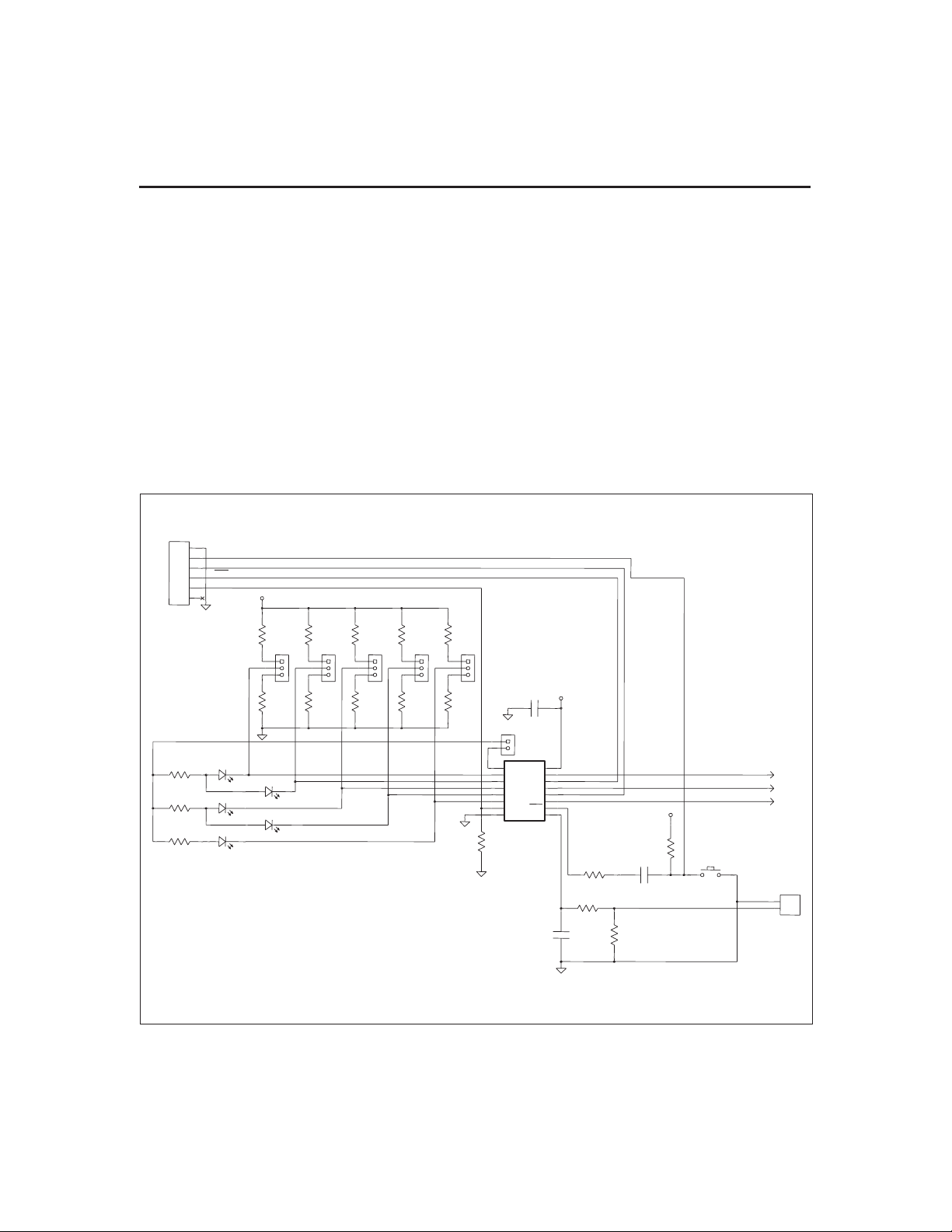
EV2014 Connections
The connections for the EV2014 are described below.
Please refer to the attached schematic in conjunction
with these descriptions.
JP1-JP8 Battery cell divider. JP1-JP6 are used
to divide the battery voltage by 5 to 10.
JP7 and JP8 are user-definable but are
configured for 11 and 12 cells on this
board.
JP9 VCC Supply. This jumper is used to se-
lect the VCC supply for the bq2014. When
JP9 is near Q2, the supply is taken from
the BAT+ input and is regulated by the
bq2014 and Q2. When JP9 is near R13,
the VCC supply is provided by LBAT+. If
VCC is supplied by LBAT+, it must not ex-
ceed the specified VCC voltage range in
the bq2014 data sheet (Dec. 1994 B or
later).
JP10-JP14 Programming pins 1-5. These jumpers
are used to configure the programming
pins. When the jumper is positioned near
the PROG# designator, the pins are
pulled high. If the jumper is in the other
position, the pins are pulled low. If the
jumper is removed, the pins are in the
high-impedance state. The board is
shipped with all pins in the high position.
Please refer to the bq2014 data sheet
(Dec. 1994 or later) for the proper con-
figuration of PROG1-5.
JP16 LED enable (LCOM connection). This
jumper connectss the LCOM pin of the
bq2014 to the LEDs. The board is
shipped with this jumper enabled.
EMPTY Empty output. This connection allows
the user to monitor the EMPTY output
pin provided on the bq2014. This pin is
high-impedance when the single-cell di-
vided battery voltage is less than the
EDVF threshold (final end-of-discharge
warning).
DSP Display input (DISP pin). DSP is con-
nected in parallel with the push-button
switch S1 provided on the EV2014 board.
An external switch configuration can be
made using DSP. When the EV2014 is
floating and detects charging or discharg-
ing, the LED outputs are active to reflect
the charge state. When the DISP input is
pulled low, the LEDs reflect the charge
state.
EV2014 Configuration
The EV2014 Evaluation Board may be used with or
without the DQ/RS-232 Interface Program. The Evalua-
tion Board should first be configured before connecting
the battery or the RS-232 cable.
Step 1 Enabling the LEDs (optional)
JP16 should be installed
Step 2 Connecting the power supply
The EV2014 can operate from power pro-
vided by the battery being monitored or
from LBAT+. Set the battery divider
(JP1-JP8) to the correct number of bat-
tery cells prior to connecting the battery.
If the bq2014 will be powered from the
battery, connect JP9 closer to Q2. If the
bq2014 will be powered from an external
supply, connect JP9 closer to R13.
Important: Connect the battery
ONLY after setting JP1-JP8 and JP9.
Step 3 Connecting the RS-232 cable
Connect the cable provided to the serial
port of any PC. Please ensure that no
2
EV2014
Rev. B Board

memory-resident programs are using this
serial port.
Step 4 Connecting the load
The external load is connected between
BAT+ and RET- (J2) on the EV2014. A
sense resistor (R16) is in series with the
negative terminal of the battery. The
EV2014 board is supplied with a 0.1, 1%
3W resistor. Please ensure that the dis-
charge load does not exceed the VSR speci-
fication for the bq2014. R16 may be
changed to a different-value resistor.
Installing the User Interface
Program
The User Interface Program (named “EV2014”) runs on
any PC-compatible computer. The program may be run
from the disk provided, or it may be installed on any di-
rectory on the computer's hard disk. To run the program
from the hard disk, simply copy all the files from the
disk supplied to the hard disk. All the files should re-
side in the same directory.
The User Interface Program installs a driver to control
the DQ/RS-232 interface. This driver asks which COM
port is connected to the EV2014 Evaluation board. If
communication is not established with the EV2014
board, the Main Menu does not appear. Please refer to
Appendix B (Troubleshooting) if the program does not
establish communication with the EV2014.
The EV2014x uses the PC-AT real-time clock to provide
the proper bit timing for serial communication with the
bq2014. The modem control lines are used as the
single-wire serial interface to the bq2014. Any TSR that
uses the PC real-time clock affects the operation of the
EV2014. For proper operation, the EV2014 should not
be operated from a DOS shell program.
If the PC is a notebook or portable type, it may be config-
ured to save battery power by adjusting the clocks ac-
cording to the activity under way. Configure the
notebook to run in “High Performance” mode for reliable
communication between the EV2014 and the PC. The
EV2014 UIP terminates if communication with the
EV2014 board is lost.
Start the User Interface Program as follows:
C>EV2014
Using the EV2014 Program
EV2014 is a menu-driven program. Almost all of the
functions and entries are made by positioning the high-
lighted cursor on the function desired and pressing the
ENTER key, or by typing a value and then pressing the
ENTER key.
Key functions are as follows:
ARROW
keys
Use the arrow keys to move the high-
lighted cursor around the screen.
ENTER
key
Press the ENTER key to select the value
currently being displayed for a parameter,
or to perform a function selected by the
highlighted cursor.
ESCAPE
key
Press the ESCAPE key to escape from
any function back to the main menu, or to
escape from any parameter value screen
back to the menu displaying that parame-
ter.
F3 key Press the F3 key to display a help file for
the selected function or parameter.
Main Menu
The Main Menu appears after the EV2014 program has
started. If this menu does not appear, communication
with the EV2014 has not been established; please refer
to Appendix B (Troubleshooting) if the EV2014x does
not display the Main Menu.
The Main Menu shows six functions that may be acti-
vated; see Figure 1. Use the cursor keys (arrow keys) to
position the highlighted cursor over the function to be
activated and press the ENTER key. For help, press the
F3 key, and a help note about the function appears.
Press the ESCAPE key to exit from the EV2014 pro-
gram.
The Main Menu functions are as follows:
<Initialize> Sends a reset command to the bq2014.
<Monitor> Activates a screen from which the bq2014
activity is monitored on a real-time basis.
<Digital
Filter>
Activates a screen from which the Digital
Magnitude Filter can be changed. The
default filter value is -0.3mV, +0.38mV.
The bq2014 data sheet (Dec. 1994 B or
later) defines valid options for this filter.
<Data Log> Allows entering a file name to which
bq2014 data will be logged, and the log-
ging period in seconds. When the log is
3
EV2014
Rev. B Board

activated, the display changes to the
Monitor screen with a top display of:
Logging Record: xx
<Display
Program
Menu>
Activates a screen showing the current
program settings for the bq2014.
<Measure
VOS>
This allows the user to determine the ap-
parent offset voltage of the bq2014 under
test. A minimum of 6 minutes are re-
quired to complete the VOS measurement,
which has a resolution of ±0.15mV per 6
minutes.
Monitor Screen
This screen monitors real-time changes of the bq2014;
see Figure 2. The program continually updates the
monitor screen. As conditions change, the new values
are displayed.
Time Time of day in HH:MM:DD, 24-hour nota-
tion.
Empty/Full This indicates the current value for GG in
the TMPGG register of the bq2014. The
capacity value is given in 116th steps.
Date Current date in MM/DD/YY notation.
NAC NAC register values multiplied by the
scale value and divided by the sense resis-
tor value to give mAh.
LMD Last Measured Discharge expressed in
terms of mAH. This is the 8-bit LMD reg-
ister value multiplied by the scale value
times 256 and divided by the sense
resistor to give mAh.
Sense Resis-
tor Value
This is the sense resistor value from the
Programming menu.
Average VSR
Current
This is the average battery current.
Time
Remaining
During discharge only, this is the time re-
maining at the average current (NAC /
Avg. VSR current)
Digital
Filter Setting
This is the value of the digital magnitude
filter.
Temp Step This is a display of the active tempera-
ture step, which ranges from 0 (for tem-
peratures <-30°C) to 12 for temperatures
> 80°C).
Activity This indicates the charging/discharging
activity occurring with the battery.
CHARGE is displayed if the battery is
charging, while DISCHARGING is dis-
played if the battery is being discharged,
or if it is idle (no charging taking place).
OVERLOAD is displayed if the voltage
drop across the sense resistor exceeds the
VSR1 threshold. Please note that the ap-
pearance of CHARGE or DISCHARGE in-
dicators is rate-dependent, and may take
some time after the application of a
charging current or a discharge load de-
pending on the PFC and scale selected,
and the rate of charge or discharge being
applied.
4
Benchmarq BQ2014 Evaluation Board Main Menu (v2.3)
<Initialize> <Monitor>
<Digital Filter> <Data Log>
<Display Program> <Measure Vos>
Please enter the SR, # of cells in Display Program for Proper Operation
ESC to exit program F3 for Help
Figure 1. Main Menu
EV2014
Rev. B Board

VSR Step This is the value of the VSR current step
as defined in the bq2014 data sheet.
GG Step This is the lower four bits of the TMPGG
register that correspond to the current
NAC value relative to either the LMD or
the original programmed full count (as
determined by PROG1-4). The GG step is
reported as a step number from 0 to 15,
with step 0 representing available capacity
from 0 to 116 of full, and 15 representing
available capacity from 1516 full to full.
Charge
Rate
Indicates whether the present charge is
TRICKLE or FAST depending on the
state of the charge rate (CR) bit in
FLGS2.
First EDV This is the state of the EDV1 flag as pro-
grammed in the Display Program Menu.
The default is 1.05V. The EDV1 flag
latches ON if VSB drops below the EDV1
threshold value. It remains latched until
charging is detected, at which time it is
cleared.
Cell voltage This is the cell voltage at the SB pin of
the bq2014.
Battery
voltage
This multiplies the cell voltage by the
number of cells programmed in the Dis-
play Program Menu. The default is one
cell.
Battery
Removed
This is the state of the battery removed
flag. It is set (BRM = yes) if one of the
conditions indicating battery removed oc-
curs. This flag is reset when the battery
is replaced.
Valid
Discharge
This is the state of the VDQ bit in
FLGS1. VDQ = yes if the bq2014 is
charged until NAC = LMD. VDQ = no indi-
5
EV2014
Benchmarq BQ2014 Evaluation Board Real-Time Monitor Screen
Time: 99:99:99 EMPTY ****_____FULL Date: 99-99-9999
NAC: 99999 mAH LMD: 99999 mAH Sense Resistor Value: XXXmΩ
Avg Vsr Current: ±9999mA Time remaining: 9999 min.
Digital Filter Setting: -0.XXmV=Vsrd +0.XXmV=Vsrq Temp Step: XX
Activity: XXXXX Vsr Current Step: XX GG Step: XX
Charge Rate: XXXX First EDV: XXX Batt. Rem'vd: XXX
Valid Discharge: XXX Final EDV: XXX Batt. Repl'd: XXX
Cell Voltage: XXX V Batt. Voltage: XXX V
Capacity Inaccurate: XXX Capacity Inaccurate Count: XXX
FLGS1:XXXXX_XX FLGS2:XXXX___X
CBBCVNEE CDDDNNNO
HRRID/DD RRRR///V
GPM QUVV 210UUUL
S1F D
ESC to main menu F1 to modify NAC F2 to modify LMD
Figure 2. Real-Time Monitor Screen
Rev. B Board

cates the present discharge is not valid for
LMD update.
Final EDV This is the state of the EDVF flag as pro-
grammed in the Display Program Menu.
The value of EDVF is 0.1V lower than
EDV1. The EDVF flag latches ON if VSB
drops below the EDVF threshold value. It
remains latched until charging is de-
tected, at which time it is cleared.
Battery
Replaced
This is the state of the battery replaced
flag. It is set (BRP = yes) if the battery
valid condition returns after setting the
battery removed flag. The battery re-
placed flag is cleared if the battery is dis-
charged to the EDV1 level or if it is
charged to NAC = LMD. This flag is set
after a EV2014x initialization.
Capacity
Inaccurate
This is the state of the capacity inaccurate
bit in FLGS1. It is set (CI = yes) to indicate
that the battery capacity has not been up-
dated during the last 64 charge cycles.
Capacity
Inaccurate
Count
This is the number of charge cycles be-
tween an LMD update. This counter is
reset to zero when NAC = LMD after a
valid LMD update.
FLGS1 This indicates the present state of the
FLGS1 resistor.
FLGS2 This indicates the present state of the
FLGS2 resistor.
Digital Magnitude Filter Menu
This menu sets the digital magnitude filter in the
bq2014; see Figure 3. Any value from 1 to 255 is valid.
Suggested values are displayed on the menu.
Modifying NAC and LMD
It is possible to change the values of the NAC and LMD
parameters from the screen using the F1 and F2 func-
tion keys as follows.
Changing NAC (F1)
1) Press the F1 key. The NAC field is highlighted.
2) Enter the value in mAH and press the ENTER
key to store the value.
Note: Changing NAC disqualifies a subsequent
LMD update.
Changing LMD (F2)
1) Press the F2 key. The LMD field is highlighted.
2) Enter the value in mAH and press the ENTER
key to store the value.
6
Rev. B Board
Benchmarq BQ2014 Evaluation Board Digital Magnitude Filter Menu
Enter DMF Value from List below: XXX
Current Setting -0.XXmV=Vsrd +0.XXmV=Vsrq
Current Threshold (DMF(mv)/Rsns): XXXXmA
Suggested DMF Settings: DMF Vsrd(mV) Vsrq(mV)
75 -0.60 0.75
100 -0.45 0.56
150 (*) -0.30 0.38
175 -0.26 0.32
200 -0.23 0.28
* = Default Value
ESC to main menu F1 to modify DMF
Figure 3. Digital Magnitude Filter Menu
EV2014

Data Logging
The data log is activated from the Main Menu by select-
ing the Data Log function. A filename to be used and the
log sample period must be entered. For example:
Log Data to Filename: <filename.ext>
Enter Sample Period (10 sec or greater):<xx>
Opening Data Log File
When the data log is started, the Monitor Screen dis-
plays the number of the current log record between the
time and date fields at the top of the screen. To termi-
nate the data log, press the ESCAPE key. The file is
closed and data logging is terminated.
The data log record contains fields of ASCII data sepa-
rated by tab characters. The field names and descrip-
tions in record order are listed below.
TIME Time record written in seconds
LMD LMD value in mAh
NAC NAC value in mAh
Avg.
Discharge
Current
Average VSR battery current
BATV Battery cell voltage
FLAGS1 Binary setting of FLAGS1 flags:
Bit Meaning
0 EDVF flag state
1 EDV1 flag state
2 Not used
3 VDQ (valid discharge)
4 Capacity inaccurate
5 Battery removed flag state
6 Battery replaced flag state
7 Charge active flag state
FLAGS2 Binary setting of FLAGS2 flags:
Bit Meaning
0 Overload flag state
1–3 Not used
4–6 Discharge rate
7 Charge rate
The log records should be readable by most spreadsheet
programs.
7
EV2014
Rev. B Board
Benchmarq BQ2014 Programming Menu
Sense Resistor: 0.1 ΩScale Factor: 1/320
Display Full: RELATIVE PFC Count: XXXXX
PFC(mVH): XXXX
Self-Discharge Battery Capacity 9999 mAH
Rate: 1/47 NAC/day
Number of Cells: X
EDV1: X.XX
Programming Pin Configuration
Prog-1 * Prog-4 *
Prog-2 * Prog-5 *
Prog-3 * Prog-6 *
F1 = SR, F2 = NOC, F3 = EDV1, ESC to main menu
Figure 4. Display Program Menu

Display Program Menu
This menu is accessed by selecting the <Display Pro-
gram> function on the Main Menu. The programming
menu allows the user to set and observe the program
state of the bq2014; see Figure 4. To change the bq2014
PFC programming, reconfigure jumpers JP6–JP10 and
initialize the bq2014. The reset allows the bq2014 to
read the program pins.
Sense
Resistor
Press F1 to enter the value of sense resis-
tor in ohms. Typical values range from
0.02 to 0.1Ω.
The sense resistor value is used by the
EV2014 UIP to develop meaningful infor-
mation in terms of A, mA, and mAH in re-
lation to battery capacity and current.
The default value is 0.1. Values from
0.005 to 0.256 are saved in the battery ID
RAM byte of the bq2014. Values greater
than 0.256 must be re-entered each time
EV2014x is started.
Scale
Factor
Select the scale factor from the available
scales using JP8 and JP9.
Like the sense resistor, the scale factor is
used to develop meaningful information for
the programmed full count tables, battery
full, and available capacity indications.
PFC Count Program full count from Table 2 from the
bq2014 data sheet.
PFC Select the programmed full count using
JP6 and JP7. Note that the selected PFC
and the sense resistor value are used to
determine the initial battery full capacity
(mAh) represented by the PFC.
Battery
Capacity
This display indicates the battery capacity
represented by dividing the PFC by the
sense resistor. In practice, picking a PFC
and sense resistor that provide a battery
full value slightly lower than (within 5%)
the rated battery capacity is recommended.
Self-
Discharge
Rate
Select one of two available self-discharge
rates depending on the application and
battery type using JP10.
Number of
Cells
Press F2 to enter the number of cells in
the battery stack. This shows the battery
pack voltage on the monitor screen.
EDV1 Press F3 to enter the desired end of dis-
charge voltage for the battery pack. The
default value is 1.05V for the bq2014.
Program-
ming Pin
Configura-
tion
This displays indicates the programming
of the bq2014 by displaying H, Z, or L de-
pending on the state of the program pins.
Please refer to the bq2014 data sheet for
further details.
8
Benchmarq EV2014 Evaluation Board VOS Measurement
Present DMF Setting -XXXmV=Vsrd +XXXmV=Vsrq
Current Threshold (DMF(mv)/Rsns): XXXXmA
Do you want to test Vos?: Y/N
Calculated Vos: Vos XXXmV, over last xxxx seconds
Elapsed time: XXXX seconds
**Note: There must be no charge/discharge activity on the bq2014 for this test
to be valid. Running the test for a longer period of time increases
the Vos measurement resolution. This test requires a minimum
of 6 minutes before any value is displayed.
Figure 5. VOS Measurement Screen
EV2014
Rev. B Board

Measure VOS Screen
This screen is used to measure the VOS of the bq2014;
see Figure 5. A minimum of 360 seconds are required to
perform this test. Pressing the ESC key terminates the
test in progress. Operating the test for a longer period
increases the resolution of the test. A “beep” signals test
completion.
Appendix A: AP14A User's
Guide
The AP14 utility (AP14A.EXE) is used to communicate
with the bq2014 on a register basis. AP14 uses a driver
to communicate with the EV2014 over serial port on a
PC-AT personal computer.
AP14
The AP14 utility is started by executing AP14A.EXE.
After AP14 is started, the following prompt is displayed:
Select COM Port<1234>
Commands
The user can respond with various commands at the
prompt. Pressing “Q” causes the program to terminate.
–> ?
Pressing the ? key displays following menu:
These commands may be used to send or receive data
from the EV2014x.
–> A
If A is entered in response to –>, then a break bit is sent
to the EV2014x. This may be used to restart the com-
munication if a problem appears. If the prompt does not
return immediately, then proper communication has not
been established; please refer to Appendix B for trouble-
shooting procedures.
–> R#
If R# is entered in response to –>, where # is an applicable
address in HEX format, AP14 returns the value at that lo-
cation from the EV2014x. The addresses are defined in
the bq2014 data sheet. For example:
–> R03
causes the display to show:
R03= ##
where ## is the current NAC value in HEX format.
Address 00 is used to read and display all readable reg-
isters.
–> S#
If S# is entered in response to –>, where # is a valid
bq2014 address in HEX format, AP14 continuously
reads and displays the value at that location. The ad-
dressed are defined in the bq2014 data sheet. For exam-
ple:
–> S03
causes the display to show:
Address3=##after XXX.XX sec.
where ## is the value at location 03 and XXX.XX is
the number of seconds between changes in this
value.
–> W# = **
If W#=** is entered in response to –>, where # is an ap-
plicable address in HEX format and ** is the value to be
written, AP14 writes the value to that location. The ad-
dresses are defined in the bq2014 data sheet. For exam-
ple:
–> W05 = A0
causes the program to write A0 in location 05hex (LMD
register).
9
EV2014
Rev. B Board
The following commands are available:
? This display is shown.
A Send break.
Q Quit and return to DOS.
R# Read at address #.
S# Scan at address #.
W# = ** Write at address # value **.

Appendix B: Troubleshooting
If the EV2014x Main Menu does not appear after start-
ing EV2014x, then communication to the bq2014 has not
been established. Please check the following:
1. Confirm the proper serial port is being used.
2. Confirm the battery divider is properly set for the
number of cells in the battery pack.
3. Confirm JP5 and JP13 are properly set for either
an external supply through LBAT+ (J1) or the mi-
croregulator.
4. Confirm the battery is attached between BAT+ and
BAT– (J1 and J2).
5. Push S1. SEG1 LED should be on indicating that
the bq2014 is properly powered.
6. If the LED is not on, check the battery voltage on
pin 16 of the bq2014 to determine if it is above 3V
but below 6.5V.
7. If the LED is on, and the EV2014x Main Menu still
does not appear, try using AP14 to establish com-
munication. Appendix A describes AP14.
8. If communication cannot be established using
AP14, the problem is either the RS-232 port in the
PC or the EV2014x interface section. Please con-
tact Benchmarq if the interface section is not work-
ing properly on the EV2014x board.
10
Rev. B Board
EV2014
CHG
DISP
DONE SR
SB
EMPTY
DQ
REF
VSS
SEG5
SEG4
SEG3
SEG2
SEG1
VCC
LCOM
BQ2014
U2
1
2
3
4
5
6
7
89
10
11
12
13
14
15
16
JP16
1
2
SEG5
D11
SEG4
D10
SEG3
D9
SEG2
D8
SEG1
D7
J2
1
2
220K
SR2
J4
1
2
3
4
5
6VCC
220K
SR2
220K
SR2
220K
SR2
220K
SR2
220K
SR2
220K
SR1
220K
SR1
220K
SR1
220K
SR1
220K
SR1
0.1
C5
470
R32
470
R31
470
R30
100K
R15
0.1
3W
R16
JP10
1
3
2
JP11
1
3
2
JP12
1
3
2
JP13
1
3
2
JP14
1
3
2
100K
R21
0.1
C4
15M
R13
VCC
DISCHARGE
S1
3 4
0.1
C6
VCC
CHG
DONE
EMPTY
REF
BAT-
DISP
SB
DQ
LCOM
PG5PG4PG3PG2PG1
CNTL
RET-
EV2014, Rev A, 8-8-96, 1 of 2
Appendix C: EV2014 Schematic

11
EV2014
Rev. B Board
0.1
C3
49.9K
R12
JP9
1
3
2
VCC
100
R14
1N752A
D13
2N7000
Q1
1N4148
D15
300K
R17 J1
1
2
200K
R4
249K
R5
301K
R6
348K
R7
402K
R8
453K
R9
499K
R10
549K
R11
J5
1
2
JP8
100
R33
1N4148
D14
100
R22
1N751A
D6
20K
R1
100K
R3
2N7000
Q2
1N4148
D3
-
+LM358N
U1
0.1
C1
0.1
C2
100K
R2
1N4148
D4
1N4148
D5
1N4148
D1
-
+LM358N
U1
1N4148
D2
P1
1
2
3
4
5
6
7
8
9
REF
BAT+
L
B
LBAT+
SB
DQ
DQ
I/O
B+ SEL
BAT DIV
12111098765
EV2014, Rev A, 8-8-96, 2 of 2
Appendix C: EV2014 Schematic (Continued)

IMPORTANT NOTICE
TexasInstruments anditssubsidiaries (TI) reservethe right tomakechanges totheirproducts or todiscontinue
any product or service without notice, and advise customers to obtain the latest version of relevant information
to verify, before placing orders, that information being relied on is current and complete. All products are sold
subject to the terms and conditions of sale supplied at the time of order acknowledgement, including those
pertaining to warranty, patent infringement, and limitation of liability.
TI warrants performance of its semiconductor products to the specifications applicable at the time of sale in
accordance with TI’s standard warranty. Testing and other quality control techniques are utilized to the extent
TIdeemsnecessarytosupportthiswarranty.Specifictesting ofall parametersof eachdevice isnot necessarily
performed, except those mandated by government requirements.
CERTAIN APPLICATIONS USING SEMICONDUCTOR PRODUCTS MAY INVOLVE POTENTIAL RISKS OF
DEATH, PERSONAL INJURY, OR SEVERE PROPERTY OR ENVIRONMENTAL DAMAGE (“CRITICAL
APPLICATIONS”). TI SEMICONDUCTOR PRODUCTS ARE NOT DESIGNED, AUTHORIZED, OR
WARRANTED TO BE SUITABLE FOR USE IN LIFE-SUPPORT DEVICES OR SYSTEMS OR OTHER
CRITICALAPPLICATIONS.INCLUSIONOFTIPRODUCTSINSUCHAPPLICATIONSISUNDERSTOODTO
BE FULLY AT THE CUSTOMER’S RISK.
In order to minimize risks associated with the customer’s applications, adequate design and operating
safeguards must be provided by the customer to minimize inherent or procedural hazards.
TIassumes no liabilityforapplications assistance or customerproduct design. TI doesnotwarrant or represent
thatanylicense,eitherexpressorimplied,isgrantedunder anypatentright,copyright,maskworkright,orother
intellectual property right of TI covering or relating to any combination, machine, or process in which such
semiconductor products or services might be or are used. TI’s publication of information regarding any third
party’s products or services does not constitute TI’s approval, warranty or endorsement thereof.
Copyright 1999, Texas Instruments Incorporated
Table of contents
Other unitrode Motherboard manuals