unitrode EV2903 User manual

Features
➤bq2903 fast charge control evaluation and
development system for rechargeable alkaline
batteries such as Renewal® from Rayovac®
➤Optional on-board 300mA current-limited charge
supply
➤Fast charge of three or four alkaline cells
➤Pulsed charge terminated by minimum current and
backed up by a maximum voltage safety termination
➤Selectable end-of-discharge voltage
➤Charge status indicator LEDs
➤Datalog capability for charge and discharge currents
through the serial port of a PC
General Description
The EV2903 Evaluation System provides a development
and evaluation environment for the bq2903 Recharge-
able Alkaline Charge/Discharge Controller IC. The
EV2903 incorporates a bq2903, a bq2014 Gas Gauge IC,
an onboard discharge N-FET, and all other hardware
needed to charge three or four rechargeable alkaline
batteries, such as Renewal from Rayovac.
Fast charge is terminated when the average charge
rate falls below approximately 3% of the fast charge
rate. For safety, charging is inhibited if the voltage of
any cell is greater than 3.0V during charge or if the
voltage of any cell is less than 0.4V when not charging
(open-circuit voltage).
The user provides batteries and DC power supply. The
user configures the EV2903 for the number of cells
(three or four), end-of-discharge voltage, and on-board or
off-board current regulation.
Contents
1 EV2903 printed circuit board containing:
a) bq2903 PDIP IC
b) All programming jumpers
c) Rayovac housing for three or four
Renewal™ batteries
d) Two status LEDs
e) RS-232 serial port interface
1 Documentation kit including data sheets,
schematics, and user’s manual
1 EV2903 User Interface Program diskette
This program runs on any PC-compatible
computer running Windows 3.x and
equipped with a standard RS-232
(COM1, COM2, COM3, or COM4) serial port,
and provides the user with a complete menu-
driven system to control, monitor, and log
data from the EV2903 Evaluation Board.
The User Interface Program communicates
with the bq2903 over the DQ serial I/O port
using the RS-232 interface
1 RS-232 Cable
1
EV2903
bq2903 Evaluation System
10/97

EV2903 Switch and Jumper
Settings
S1 Cell Selection. S1 selects three-cell (set
to 3) or four-cell (set to 4) configuration.
JP7 Supply Regulation. Set jumper JP7 to
INT-I to use the on-board, voltage-limited
current source. Set JP7 to EXT-I to select
off-board charging supply.
JP9 EDV. JP9 selects the end-of-discharge
voltage at which the bq2903 disconnects
the battery stack from the load. To select
1.0V EDV, leave jumper off to let VSEL
floating.
JP8 Internal or External Discharge FET.
JP8 selects the external FET for discharge
loads greater than 400mA. Set jumper to
EN to enable the external FET, or set it to
DIS to disable the external FET.
EV2903 Connections
J1 DRV. Auxiliary discharge FET driver out-
put from the bq2903 to connect to gate of a
user-selectable, external FET. Source should
be connected to GND and drain to LOAD-.
DONE. This TTL-compatible output sig-
nifies a charge completion by going high.
Valid only when DC is applied.
GND. Charging supply ground.
LOAD+. Connection for the load to the
high side of the battery stack.
LOAD-. Connection for the load return.
J2 Use this connection when using the on-
board voltage-limited current source. This
connector accepts an unregulated voltage
between 9-15V DC at a minimum of 300mA.
JP7 should also be in the INT-I position. Do
not use J3 in conjunction with J2.
J3 Use this connection when bypassing the
on-board current source and providing an
external charging source. The external
supply should be a 300mA current source
with a voltage compliance between 8-10V.
JP7 should also be in the EXT-I position.
J2 should not be used in conjunction with
J3.
P1 Serial data bus connection. This con-
nection is made to the RS-232 cable con-
necting to the serial port of the PC.
EV2903 Configuration
The EV2903 Evaluation Board operates with or without
the Interface Program. Configure the board first before
connecting the batteries and the RS-232 cable.
Step 1 Configure all switches and jumpers to
their desired settings. The factory de-
fault settings are:
JP7: INT-I
JP9: EDV = 1V
JP8: External FET
Step 2 If using an off-board discharge load FET,
connect the gate to the DRV output on J1,
connect the source to GND on J1, and
connect the drain to LOAD- on J1.
Step 3 Connect the DC power supply to either J2
or J3, depending on the use of external or
on-board regulation.
Step 4 Connect the RS-232 cable to connector P1
on the EV2903 and to an available serial
port on the PC (optional).
Installing the User Interface
Program
The EV2903 board uses a bq2014 Gas Gauge chip on
board to monitor the state of charge of the batteries and
to provide an easy user interface to this evaluation
board. The user communicates with the bq2014 through
the User Interface Program, which runs on any IBM
PC-compatible computer in the Windows 3.x environ-
ment (a 486-33MHz or better is recommended).
Before running the program, you must first install it
from the floppy disk to the hard drive. To install the
User Interface Program, insert the diskette into the disk
drive and choose Run from the File menu in Program
Manager. Type “A:\setup” (substituting the appropriate
drive letter for “A”) and press Enter. The installation
program will prompt for the destination directory (select
“OK” to accept the default).
Using the EV2903 Program
To run the program, double-click on the EV2903 icon in
the EV2903 program group. All of the status monitors
and functions are controlled from the EV2903 Interface
screen, Figure 1.
2
EV2903

Selecting a Communications Port
The EV2903 program displays the port selection dialog
box (as shown in Appendix A) the first time that the pro-
gram is run. You must specify to which communications
port (1-4) the EV2903 is connected. Specify the correct
port by clicking first on the appropriate selection and
then on the “OK” button. After several seconds, the pro-
gram will display an information box confirming that
communications have been established. Please note that
the program then saves this information to the hard
drive, so the port selection box will not appear again
during subsequent use of the program.
Interface Screen
The Interface screen appears after the program has
started and communication has been established with
the EV2903 board. If this screen does not appear, please
refer to Appendix A (Troubleshooting) for possible solu-
tions.
Display and Functional Buttons
The Interface screen shows four buttons for display and
functional purposes:
Select this button to show either three or
four cells in use. This button is for dis-
play only to remind the user of configura-
tion.
Select this button to show EDV. This but-
ton is for display only to remind user of
configuration.
Use this button to calibrate in the battery
stack voltage. Select it and then enter
the measured stack voltage to calibrate
the Battery Stack Voltage display.
Click on this button to start a datalog.
Enter the filename where the datalog will
be saved and an optional line of text
which will be placed on the first line of
the datalog.
3
EV2903
Figure 1. EV2903 Interface Screen

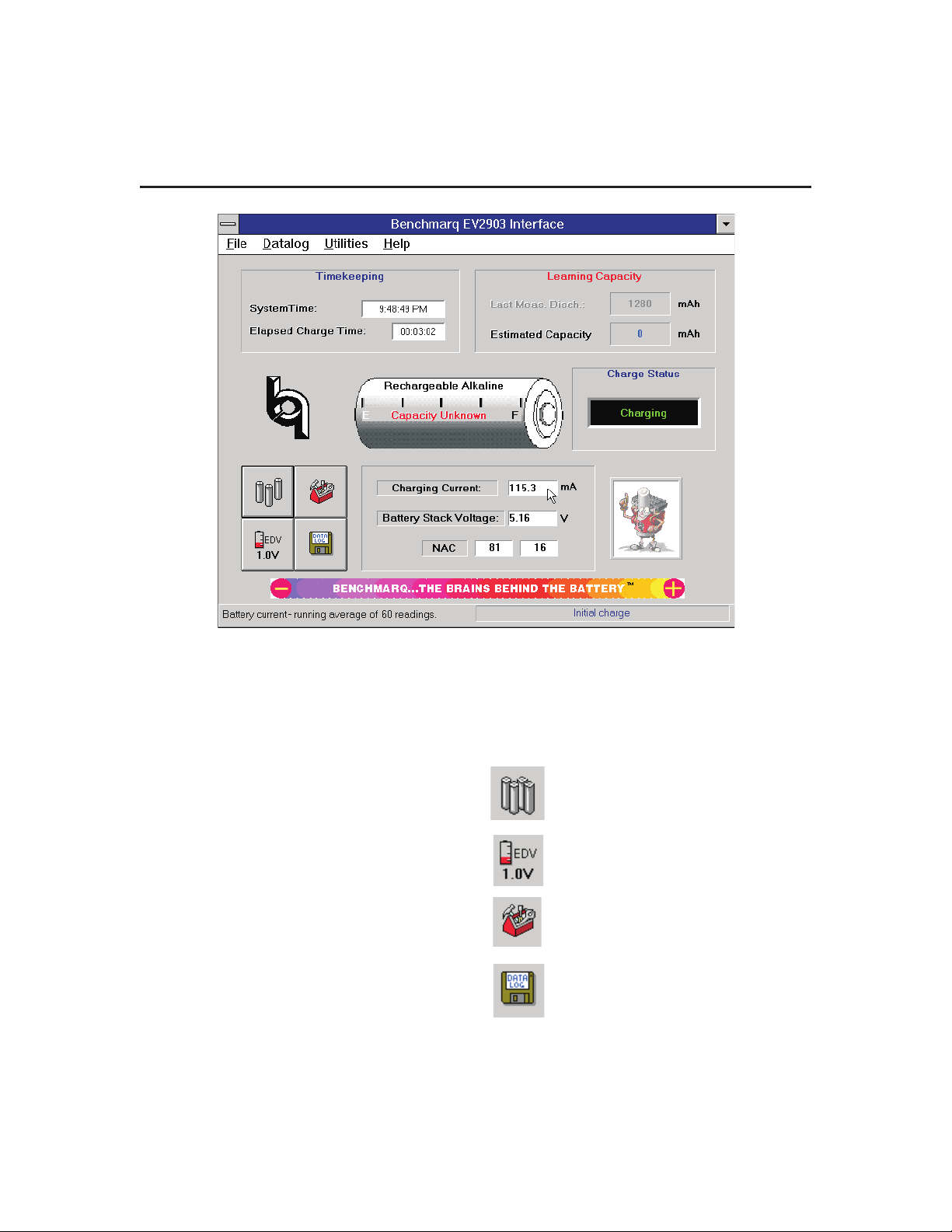
Real-Time Monitoring
The EV2903 Interface screen provides real-time moni-
toring of the current status of the battery stack. As con-
ditions change, the new values are displayed:
Current Time:
This displays the current time generated from the PC’s
real-time clock.
Elapsed Charge/Discharge Time:
This provides the elapsed time from the moment that a
charge/discharge is initiated.
Last Meas. Disch:
The Last Measured Discharge (LMD) is the last meas-
ured discharge capacity of the battery stack. The LMD
display will be updated only if a complete battery dis-
charge from full to empty occurs without any partial
battery charges. The “Learning Capacity” message will
continue to flash until the Last Meas. Disch. display is
updated, meaning the EV2903 has learned the batteries’
capacity.
Estimated Capacity:
This is the estimated capacity, or current battery state-
of-charge. This value will not be valid until the “Learn-
ing Capacity” message is not flashing. This value will
decrement during discharge and increment during
charge.
Charge Status:
Charge Status displays the charging/discharging activ-
ity occurring with the batteries. These messages will be
displayed depending on the status.
Charging The batteries are taking on a charge.
Discharging The batteries are discharging to the load.
Full The batteries are fully charged and have
terminated charging.
Empty The batteries have met the EDV limit and
are disconnected from the load.
Idle The batteries are neither charging nor
discharging.
Charging/Discharging Current:
This is the average charging/discharging battery cur-
rent. “N/A”will be displayed as the averaging routine is
averaging the current. Under the Utilities menu, you
can select the number of datapoints included in the av-
erage. By selecting a higher number of datapoints, a
plot of the data will be smoothed. Benchmarq suggests
60 datapoints.
Battery Stack Voltage:
This is the battery stack voltage as measured by the
bq2014 gas gauge and displayed by the EV2903.
While charging, the battery stack voltage may appear to
jump around. This action is due to the voltage being
sampled at various times, either during the charging
pulse or during the idle period. Refer to the bq2903
data sheet for charging activity.
When EDV is met, the Battery Stack Voltage will dis-
play “N/A” when the battery stack is disconnected from
the load.
Battery Gas Gauge:
The picture of the battery provides a bar graph depict-
ing the current state of battery capacity. The bar graph
shows “Estimated Capacity” as a percentage of “Last-
Measured Discharge.” The gas gauge will not display
capacity until the EV2903 has learned the battery ca-
pacity. The EV2903 is still learning the battery capacity
as long as the “Learning Capacity” message is blinking.
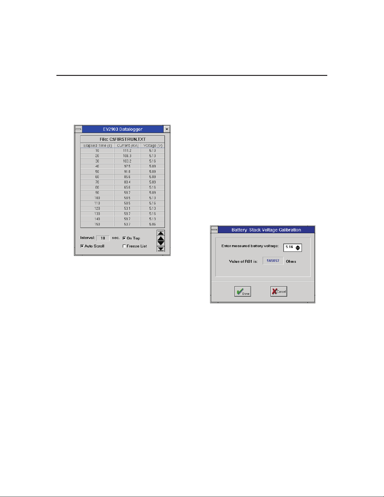
Data Logging
The EV2903 provides for data logging these values:
■Battery Stack Voltage
■Charge/Discharge Current
■Elapsed Time in Seconds
The datalog is activated from the datalog button on the
Interface screen or by selecting “Start Log” from the Da-
talog menu. When selected, a comment screen will ap-
pear, allowing one line of text to be included on the first
line of the datalog. After the comment screen, a prompt
dialog box will appear asking for a file name to which to
save the data log. If <Cancel> is selected, the data log
screen will still appear, but the data will not be saved.
The datalog screen at the bottom will scroll the informa-
tion as it is taken. Screen options allow for either freez-
ing or auto-scrolling the datalog list. The onscreen
datalog list will contain the last 200 datapoints taken,
but all the datapoints are saved to the hard drive (if you
have entered a file name)
The check boxes allow perusal of the data contained in
the list (up to the last 200 datapoints). Auto-scroll en-
ables the list to scroll up every time a new datapoint is
added, making the latest datapoints always visible.
When not checked, the list does not scroll, but you can
manually scroll using the arrow buttons. Freeze list
temporarily disables auto-scrolling while viewing data-
points. Clicking the scroll buttons or on any datapoint
in the list will automatically freeze the list.
4
EV2903

Click on Freeze List to disable and re-enable auto-
scrolling. The On Top check box causes the datalog win-
dow to remain on top of other windows; when un-
checked, other windows may cover up the datalog
window. You may minimize the datalog window at any
time without disrupting the datalogging process.
The Datalog Settings on the menu bar provides for set-
ting the time interval between each point datalogged.
This pull-down menu provides options with a minimum
of five-second intervals. Another option allows stopping
the datalog when the EV2903 detects that the batteries
are idle.
The datalog is saved as a text (.txt) file. If you desire a
plot, we suggest importing into a program such as Micro-
soft Excel.TM
Standard Operation and Helpful
Hints
Learning the Battery Capacity
Upon initialization of the program and/or inserting a dif-
ferent or new set of batteries, preferably start out by
charging the batteries to “Full.” Then, discharge the
batteries until “Empty.” Doing this will allow the
EV2903 to “learn” the capacity during the first discharge
cycle.
Batteries
For optimal battery performance, replace batteries as a
complete set. The EV2903 charges the battery stack in
series and not each cell individually. Charging termina-
tion takes place when any cell is fully charged. Dis-
charging terminates when any cell reaches EDV. Please
refer to the bq2903 data sheet.
Battery Stack Voltage (EDV)
When the bq2903 senses EDV, it disconnects the battery
stack from the load. At this time, the bq2014 Gas Gauge
cannot sense the battery stack voltage, sensing only 0
volts. The battery stack voltage will decrease quickly
due to the averaging routine internal to the bq2014.
When the EV2903 detects EDV, it will display “N/A” as
the Battery Stack Voltage.
Calibrating Battery Stack Voltage
The Battery Stack Voltage display should be within
±90mV of the true battery stack voltage. For better ac-
curacy, use the Calibration button. Measure directly
across the battery stack and input this value in the Cali-
bration window. Select Done.
For three- and four-cell calibration, measure directly
across the “+” terminal of battery 1 to the “-” terminal of
battery 3.
Message Status Bar
The lower right-hand corner of the EV2903 screen will
display helpful messages throughout the operation of
the EV2903 program. This message bar will indicate
the number of complete charge and discharge cycles.
Utilities Menu
Use this menu to calibrate the battery stack voltage and
to set the number of data points which the EV2903 uses
to average the current. Benchmarq suggests using 60
data points, which will smooth out graphs showing the
current.
Also in the Utilities menu are options for the Register
window and Flag window. Use these windows to moni-
tor the status of the bq2014. Please refer to the bq2014
data sheet for information concerning these registers
and flags.
5
EV2903

Appendix A: Troubleshooting
If the EV2903 Interface screen does not appear after
starting the program, then communication to the
EV2903 Evaluation board has not been established.
Please check the following:
Time-Out Error
On occasion, we have noticed that a communication
time-out error will occur. In most cases, clicking “OK”
will resume operation.
6
EV2903

7
EV2903
0.01UF
C9
0.01UF
C10
0.01UF
C11
1UF
C8
35V
10UF
C1
35V
10UF
C2
13K
R11
1K
R12
820
R13
1K
R14
1K
R23
1K
R2
1K
R1
3W0.1
R8
2.2
R6
1K
R3
1K
R4
1K
R5
1.5K
R22
1N5821
D10
LRTN
VSS
VSS
LRTN
DC
BAT1P
DRVCHG
DONE
BAT3N
BAT2N
BAT1N
NSEL
VSEL
BQ2903
U1
1
2
3
4
5
6
78
9
10
11
12
13
14
J1
1
2
3
4
5
6
CHARGE/RED
D1
DONE/GREEN
D2
VOLT
RENEWAL1
VOLT
RENEWAL3
1
VOLT
RENEWAL2
VOLT
RENEWAL4
IRLZ34
Q1
CELL_SEL
S1
12
3
45
6
JP7
JP8
JP9
1N4001
D9
1N4001
D4
1N4001
D11
J2
1
2
J3
1
2
SHEET_2
SHEET_2
SHEET_2
SHEET_2
TIP42
Q2
2N4403
Q3
2N3904
Q4
VP0104
Q5
DRV
BAT+
ISNS
DONE
DONE
DIS
EN
LD+
LD-
DONE
3 CELL
4 CELL
GND
GND
DRV
GND
GND
I+
V+
EDV
0.9V
1.0V
1.1V
EXT-I
EV2903/4-24-97/F
Appendix B: EV2903 Schematic

8
EV2903
0.1UF
C18
0.1UF
C4
0.1UF
C5
0.1UF
C6
0.1UF
C7
1K
R21
1%
200K
R9
20K
R18
20K
R16
20K
R19
1K
R20
1%
487K
R10
200K
R7
1K
R15
20K
R17
VCC
VCC
VCC
VCC
-
+
LM358N
U4
-
+LM358N
U4
1N751A
D12
JP3
1
3
2
JP4
1
3
2
JP5
1
3
2
JP6
1
3
20.1UF
C3
SHEET_1
SHEET_1
SHEET_1
SHEET_1
1N4148
D8
1N4148
D7
1N4148
D3
1N4148
D6
1N4148
D5
P1
1
2
3
4
5
6
7
8
9
CHG
DISP
DONE
SR
SB
EMPTY
DQ
REF
VSS
SEG5
SEG4
SEG3
SEG2
SEG1
VCCLCOM
BQ2014
U3
1
2
3
4
5
6
7
89
10
11
12
13
14
15
16
DRV
BAT+
ISNS
DONE
PG1PG2PG3PG4
DATA COLLECTION
EV2903/4-24-97/F2
Appendix B: EV2903 Schematic Continued

IMPORTANT NOTICE
TexasInstruments anditssubsidiaries(TI) reserve therighttomake changestotheirproducts ortodiscontinue
any product or service without notice, and advise customers to obtain the latest version of relevant information
to verify, before placing orders, that information being relied on is current and complete. All products are sold
subject to the terms and conditions of sale supplied at the time of order acknowledgement, including those
pertaining to warranty, patent infringement, and limitation of liability.
TI warrants performance of its semiconductor products to the specifications applicable at the time of sale in
accordance with TI’s standard warranty. Testing and other quality control techniques are utilized to the extent
TIdeemsnecessaryto support thiswarranty.Specifictestingof allparameters ofeachdeviceisnotnecessarily
performed, except those mandated by government requirements.
CERTAIN APPLICATIONS USING SEMICONDUCTOR PRODUCTS MAY INVOLVE POTENTIAL RISKS OF
DEATH, PERSONAL INJURY, OR SEVERE PROPERTY OR ENVIRONMENTAL DAMAGE (“CRITICAL
APPLICATIONS”). TI SEMICONDUCTOR PRODUCTS ARE NOT DESIGNED, AUTHORIZED, OR
WARRANTED TO BE SUITABLE FOR USE IN LIFE-SUPPORT DEVICES OR SYSTEMS OR OTHER
CRITICALAPPLICATIONS.INCLUSIONOFTIPRODUCTSINSUCHAPPLICATIONSISUNDERSTOODTO
BE FULLY AT THE CUSTOMER’S RISK.
In order to minimize risks associated with the customer’s applications, adequate design and operating
safeguards must be provided by the customer to minimize inherent or procedural hazards.
TIassumes no liabilityforapplications assistanceorcustomerproduct design.TIdoes notwarrantorrepresent
thatanylicense,eitherexpressorimplied,isgrantedunderanypatentright,copyright,maskworkright,orother
intellectual property right of TI covering or relating to any combination, machine, or process in which such
semiconductor products or services might be or are used. TI’s publication of information regarding any third
party’s products or services does not constitute TI’s approval, warranty or endorsement thereof.
Copyright 1999, Texas Instruments Incorporated
Table of contents
Other unitrode Motherboard manuals