Copyright © 2012 Universal Scientific Incorporated. All rights Reserved. www.universalscientificinc.com
6210 Campbell Drive. Madison, Ohio 44057-2003 | Phone: 440-428-7800 | Fax: 440-428-8650 Page 6
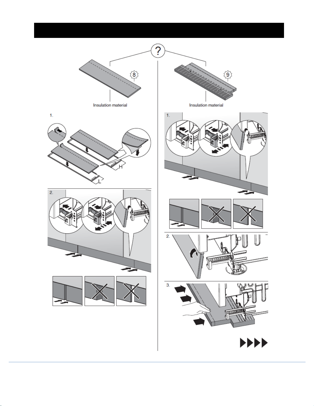
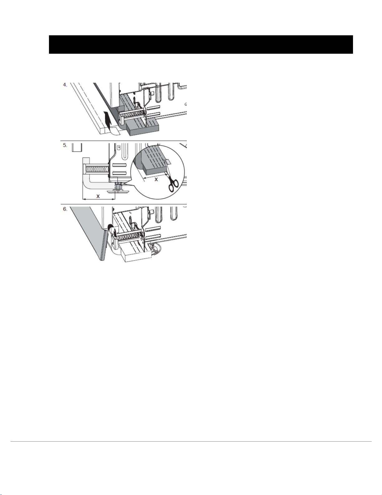
MOVING THE MACHINE INTO PLACE
ADJUSTING MACHINES WITH THREE OR FOUR
FEET
1. Position the machine in front of the cabinet
opening.
2. Push the plastic feet into place on all steel feet
(included in document bag).
3. Start by measuring the height from the floor to
the bottom edge of the counter top. Measure
the height from the floor to the top edge of
the dishwasher.
4. Loosen the lock nuts on the dishwasher’s steel
feet using a 5/8˝ (16 mm) open
-ended
wrench. Screw the lock nuts down as close to
the floor as possible.
5. Make the height adjustment while the
dishwasher is in front of the opening. Adjust
all feet by turning them clockwise to raise or
counterclockwise to lower the dishwasher.
6. Check that the height of the machine
corresponds to the height from the floor to
the bottom edge of the counter top.
7. Tighten the lock nuts (lock nut) on the rear
feet (foot).
8. Pull out the drain hose to ensure there are no
sharp bends.
9. Start to feed water and drain lines and electric
cord (if necessary) into the access hole(s) in
the cabinet.
10. Gently slide the unit into the dishwasher
opening. As you do this, feed the drain line
and inlet hose into the access hole(s) in the
side of the cabinet.
11. If installing in a metal cabinet, the hole(s) for
the drain hose and connection pipe must be
fitted with edge protectors/rubber grommets.
12. Place the spirit level on the dishwasher door
to check that the machine is level and adjust if
necessary. The door must be fully closed!
13. Make any final adjustments to the front feet.
(The machine may have an inclination of
3/16˝ (5 mm) maximum without affecting its
performance.)
14. When the front feet are properly adjusted,
tighten the lock nuts to the base pan.