Universal HP-100NI User manual

Page 1 of 27
OPERATION - MAINTENANCE
UNIVERSAL STENCILING & MARKING SYSTEMS, INC.
P.O. BOX 871 - ST. PETERSBURG, FLORIDA 33731 USA
PH: (727) 894-3027 FAX: (727) 821-7944
POROUS
HAND PRINTER
ALL MODELS
OWNER’S MANUAL
STENCILING & MARKING SYSTEMS
PHP-18122

Page 2 of 26
UNIVERSAL products are manufactured to exacting standards and every available
step has been taken to assure your complete satisfaction. It is most important,
however, that the instructions contained in this manual are read and carefully
followed for best results. Failure to do so may result in unsatisfactory
performance, damage to the equipment and personal injury.
IMPORTANT NOTE
TABLE OF CONTENTS
UNIVERSAL Hand Printers are guaranteed to be free from defects in materials and
workmanship for a period of 90 days from the date of purchase. Components found to be
defective during this time will be repaired free of charge if returned to the factory. Damage
resulting from use of improper inks, improper installation, or operation is not covered
under the scope of this warranty. For warranty service please contact our Customer
Service Department.
- LIMITED WARRANTY -
3
4
4
5
6
6
7
9
10
12
16
18
20
○○○○○○○○○○○○○○○○○○○○○○○○○○○○○○
○○○○○○○○○○○○○○○○○○○○○○○○○○○○○○○
○○○○○○○○○○○○○○○○○○○○○○○○○○○○○○
○○○○○○○○○○○○○○○○○○○○○○○○○○○○
○○○○○○○○○○○○○○○○○○○○○
○○○○○○○○○○○○○○○○○○○○○○○○○○○
○○○○○○○○○○○○○○○○○○○
○○○○○○○○○○○○○○○○○○○
○○○○○○○○○○○○○○○○○○○○
○○○○○○○○○○○○○○
○○○ ○○○○○○○○○○○○○○
○○○○○○○○○○○○○○○○○
SPECIFICATIONS
HP-100NI
HP-200
HP-200NI
Printing Die’s
Optional Type Blocking Kit
Ink Rolls & Inks
QUICKSTART
Pre-inking the Microcell Ink Roll
Re-inking the Microcell Ink Roll
MAINTENANCE
Replacing the Drum Covering
Replacing the Print Drum Index Spring on the HP-200 Indexing Coder
Adjusting the tension of the Index Spring
Assembly of the Ink Roller Eccentric
PARTSDIAGRAMS& PARTSLISTS

Page 27 of 27Page 3 of 26
HP-100NI HAND PRINTER
SPECIFICATIONS
NET WEIGHT: 1LB - 6 OZ. / 0.614 KG.
MAXIMUM DIE SIZE - US STANDARD: 2” (15 RIBS) X 5-9/16” LONG
MAXIMUM DIE SIZE - METRIC CODERS ONLY: 50.8 MM (14 RIBS) X 141.3 MM LONG
PRINT DRUM CIRCUMFERENCE: 6.5” (165 MM) MEASURED AT DIE FACE

Page 4 of 26
HP-200 & HP-200NI HAND PRINTER
SPECIFICATIONS
HP-200: NET WEIGHT: 1 LB. - 12 OZ. / 0.781 KG.
MAXIMUM DIE SIZE - US STANDARD: 2” (15 RIBS) X 8-3/8” LONG
MAXIMUM DIE SIZE - METRIC CODERS ONLY: 50.8 MM (14 RIBS) X 212.7 MM LONG
PRINT DRUM CIRCUMFERENCE: 9.1” (231 MM) MEASURED AT DIE FACE
MAXIMUM DIE SIZE - US STANDARD: 2” (15 RIBS) X 8-3/8” LONG
MAXIMUM DIE SIZE - METRIC CODERS ONLY: 50.8 MM (14 RIBS) X 212.7 MM LONG
PRINT DRUM CIRCUMFERENCE: 9.1” (231 MM) MEASURED AT DIE FACE
HP-200NI: NET WEIGHT: 1 LB. - 11 OZ. / 0.753 KG.

Page 5 of 26
SPECIFICATIONS
Figure 1
The Universal HP-100NI, HP-200NI and HP-200 hand printers are designed for
the hand application of printed data on cartons, bags and other flat, porous surface
materials
The HP-100NI and HP-200NI machines are non-indexing or continuous roll de-
signs. The HP-200 machine is an indexing or spot printing design which allows for
accurate print registration and eliminates duplication of data.
RIBtype® PRINTING DIES
Universal Coders are designed to use
RIBtype® printing dies which have a molded
rib backing. The ribs on the back of the die
snap into mating ribs in the ribtype drum cover
on the print drum as shown in Figure 1. Al-
thoughthere areseveral competitive ribbacked
die systems available, it is very important to
note that they are not all made to the same
specifications and are not interchangeable.
Dies are available in many standard character styles and sizes in sets containing
a combination of individual alphabetic and numeric characters or in sets of nu-
meric characters only. These character sets or “sorts” can be used to make up
text messages and code numbers as necessary. Dies are also available in
“logo” form in which a complete text message is produced on a single piece of rib
backed rubber. Logo dies are much faster to change and normally produce better
print quality since they are more dimensionally stable than individual characters
when installed on the print drum.
Universal also offers RIBtype® Metric Die systems for use in countries where
metric character sizes are the standard. The Metric dies are thicker and the rib
spacing differs slightly from the standard printing dies therefore the two versions
are not compatible. To accommodate the differences, the print drums for Metric
dies are machined to a slightly different diameter from the U.S. versions.
The coder model numbers on Metric coders will have a “-T” suffix and the Metric
Drum Covers have a distinct pink color.
METRIC RIBtype® PRINTING DIES

Page 6 of 26
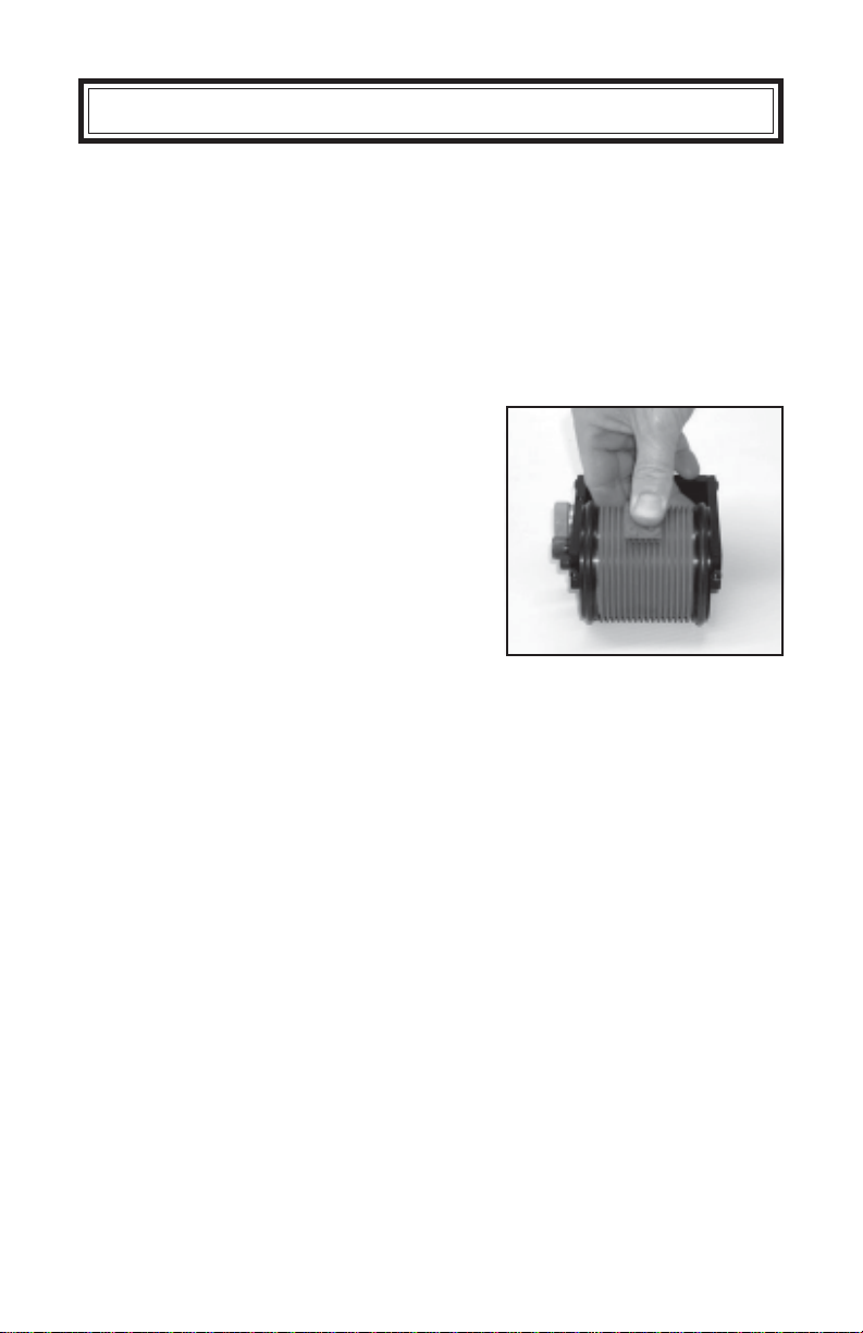
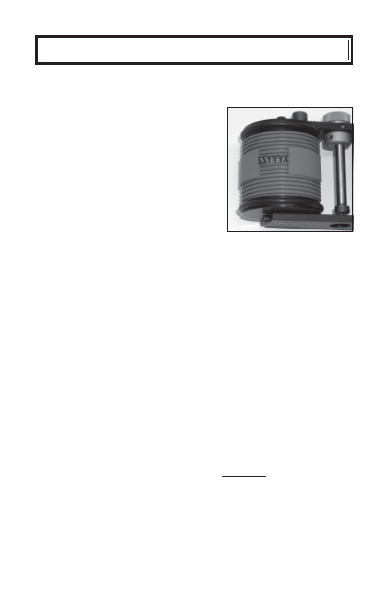
MICROCELL ROLLS: The standard ink rolls shipped with Universal Hand Print-
ers are made from reticulated urethane foam. This material is one of the most
durable ink roll materials available and with proper care should last in excess of
one year before replacement becomes necessary. Microcell rolls should be inked
with Universal No. 1150 porous coder ink only. It is extremely important to fol-
low the inking instructions or roll performance will be adversely affected.
INK ROLLS & INKS
SPECIFICATIONS
XF NEOPRENE ROLLS: Universal’s XF Neoprene Ink Rolls are made from an
extra firm density neoprene material. While not quite as durable as Microcell, the
extremely fine cell structure of these rolls provides exceptionally good print quality,
particularly when using small character printing dies. Due to their greater ability to
compensate for slight die thickness variations, these rolls are also recommended
to correct print quality problems when multiple lines of text are required.
Although these Hand Printers are not designed for production use with alcohol
base marking inks, the XF Neoprene Ink Rolls are compatible with a variety of
alcohol base inks. For limited use applications, slow drying alcohol base inks can
be used on the XF Neoprene ink rolls for marking on Non-Porous surfaces such as
metal,plastic,glass, etc. Pleasenote that thealcohol innon-porous inkswill evapo-
rate rapidly leaving the rolls dry and hard in a relatively short period of time. After
use with alcohol base inks, the rolls should be immediately removed from the coder
and stored in an air tight container.
OPTIONAL TYPE BLOCKING KITS
When using small individual characters with
onlya twoor threerib backing,anoptionalType
BlockingKit (stock no.UR-BK) should beused
to support the leading and trailing ends of the
type as shown.
Characters which have only a 2 or 3 rib back-
ing do not have the stability of the larger char-
acter sizes when snapped into the drum cover.
Addingthe ribbacked typeblocks onboth ends
ofthe code willprovide addedstability andpre-
vent the characters from shifting during print-
ing. The Type Blocks are not as thick as the
Type and will not pick up ink from the Ink Roll. FIGURE 2

Page 7 of 26
QUICK START
PRE-INKING THE MICROCELL INK ROLL
Universal Hand Printers are shipped from the factory fully assembled and, unless
otherwise specified, include a dry Microcell Ink Roll. The Ink Roll must be manu-
ally pre-inked prior to use. The initial inking of a dry roll is a critical process. The
following instructions will guide you through the inking and installation process and
have your coder ready to use in a few minutes.
Microcell Ink Rolls are designed for use with Uni-
versal #1150 Ink for marking on porous surfaces.
Inks will stain clothing, furniture, carpeting and your hands. Rubber gloves
should be worn during the following procedures.
1 - Fill a clean dry container with enough ink
to allow the ink roll to fully submerge.
2 - Carefully place the ink roll into the ink.
Do not force the roll to submerge. The
top surface of the roll must remain dry
during this process.
The roll should be allowed to float, undisturbed, in
the container of ink. Leaving the top surface of the
roll dry allows air to escape as the ink is absorbed
from the bottom. When the roll sinks under the
surface of the ink, it is fully saturated.
3 - Remove the ink roll from the container by
inserting a screwdriver through the core.
4 - Roll the ink roll over paper towels or a piece
of scrap cardboard to remove excess ink.
Therollswillbeexcessivelysaturatedafterremoval
from the container. Remove enough ink from the
roll so the surface does not appear wet. Use a
clean paper towel to blot the ink from the ends of
the core before installation on the coder.
Let the excess ink drip into the container.
FIGURE 3
FIGURE 4
FIGURE 5
FIGURE 6

Page 8 of 26
Grip the Ink Roll Eccentric Adjusting Knob with one
hand. Insert a 3/16” hex wrench through the ac-
cess hole in the side frame of the coder and turn the
Ink Roll Axle counterclockwise until loose. Pull the
Ink Roller Axle out through the access hole.
6 - Remove the Ink Roller Axle from the coder.
7 - Position the ink roll between the two side
frames of the coder and insert the Ink Roll
Axle through the Ink Roll core.
8 - Install the printing dies by aligning the ribs
on the die back with the matching grooves
on the print drum.
5 - Rotate the Ink Roll Eccentric Knob until the
Ink Roll Axle is at its farthest position away
from the print drum.
While gripping the Ink Roll EccentricAdjusting Knob
with one hand, tighten the Ink Roll Axle using the 3/
16” hex wrench.
QUICK START
In this position, the ink roll will not contact the print
drum during installation.
Start with one end and press the die into the print
drum cover until the die is fully engaged.
Tip to make die installation easier when installing larger logo dies: Moisten a
sponge with water containing a few drops of liquid dish detergent. Lightly moisten
the back of the printing die and then immediately press the die into the drum cover.
Do not apply too much liquid or the dies will slip during printing. Never apply any
other lubricants such as oil or silicone or the dies will not hold properly.
FIGURE 7
FIGURE 8
FIGURE 9
FIGURE 10

Page 9 of 26
9 - Adjust the Ink Roller Eccentric Knob to a
position where the ink roll just contacts the
die faces when the print drum is rotated.
Ink should only be applied to the die face, not the
sides or backing of the die. Excessive contact pres-
sure will result in an excessively wet and smudged
impression.
RE-INKING THE MICROCELL INK ROLL
10 - Your coder is now ready for use.
After the initial inking process, the Microcell Ink
Rollcan be re-inkedby carefullysquirting a small
amount of ink on the roll surface. It is best to
apply very small amounts of ink down the length
of the roll in multiple places rotating the roll
after each pass. Do not apply an excess amount
of ink or print quality will suffer.
FIGURE 11
FIGURE 12
QUICK START

Page 10 of 26
MAINTENANCE
REPLACING THE DRUM COVERING
1 - Lay the coder on it’s side as shown and
using a 5/64” hex wrench, loosen the set
screw in the end of the top Side Frame.
Donotloosenthe set screw in thebottomsideframe.
Replacing the Drum Covering requires removal of the print drum. The following
steps explain the process. For Indexing Coders, see Page 12 under Index Spring
Replacement for Print Drum removal instructions.
2 - Remove the two button head screws which
hold the Side Frame to the Back Frame us-
ing a 3/32” hex wrench.
3 - Lift the Side Frame off the coder.
4 - Pull the Print Drum off the Axle.
A slight wiggling action of the Side Frame may help
in this process.
Be careful not to lose the thin brass washers lo-
cated on either side of the print drum.
FIGURE 13
FIGURE 14
FIGURE 15
FIGURE 16

Page 11 of 26
MAINTENANCE
5 - Remove one of the Rubber Friction Bearer
Rings.
It does not matter which one is removed.
6 - Remove the old Print Drum Cover by grip-
ping one edge with your fingertips and roll-
ing the cover towards the end of the Print
Drum where the friction bearer was re-
moved.
7 -To install the new Drum Cover, stretch one
end of the cover over the end of the Print
Drum without the friction bearer.
8 - Pull the cover down in small steps, rotating
the drum and pulling in different areas as
you progress.
9 - Replace the Rubber Friction Bearer Ring
and reassemble the coder in the reverse
order of the disassembly process.
Moistening the inside of the Drum Cover with a so-
lution of water and a few drops of liquid dish deter-
gent will make this process easier.
These rings are tight and installation does take a bit
of effort. Do not use pliers to grip the rubber ring or
it will tear.
Besuretheprintdrumbrasswashersarereinstalled
on either side of the print drum.
FIGURE 17
FIGURE 18
FIGURE 19
FIGURE 20
FIGURE 21

Page 12 of 26
REPLACING THE PRINT DRUM INDEX SPRING
ON THE HP-200 INDEXING CODER
Replacing the Index Spring requires removal of the print drum. Please follow these
same disassembly steps for replacing the Drum Cover.
1 -Remove the Index Stop Pin and Washer us-
ing a 5/16” hex wrench.
If you are only replacing the Drum Cover, hold the
Print Drum from rotating when this pin is being re-
moved. As soon as the Stop Pin is removed the
index spring will relax, rotating the print drum in the
process.
2 -Loosen only the top Print Drum Axle Re-
taining Screw using a 9/64” hex wrench.
3 -Pull the Spring Tension Adjuster out of the
Axle.
4 -Remove the two button head screws that
hold the Side Frame to the Back Frame us-
ing a 3/32” hex wrench.
The Tension Adjuster has a flat body which fits into
the slotted end of the Print Drum Axle. This part is
used to pretension the Index Spring as explained
later.
Note: Both Side Frames can be removed, however,
for Print Drum removal purposes, remove only the
Side Frame with the Ink Roll Eccentric Knob as
shown in Figure 25.
Leaving the bottom screw tight will simplify the re-
assembly procedure.
FIGURE 22
FIGURE 23
FIGURE 24
FIGURE 25
MAINTENANCE

Page 13 of 26
5 -Lift the Side Frame off the coder.
6 -Lift the Print Drum off the Axle.
7 -Remove the Index Cam.
8 -If the Index Spring is broken, pull the broken
spring out of the Print Drum through the
hole where the Index Cam was removed.
9 -Remove the small white bushing.
After the spring is removed, shake the drum and
listen for any loose spring fragments. Ensure that
all loose pieces of spring are removed.
A slight wiggling action may help disengage the
Side Frame from the Print Drum Axle.
TheIndexCamonthisunit enables the Print Drumto
rotate 365 degrees before hitting the Stop Pin. This
unique feature increases the usable area of the
Print Drum for printing dies.
Figure 26
Figure 27
Figure 28
Figure 29
Figure 30
MAINTENANCE
Set the Print Drum on two 1/2” or thicker blocks
with enough gap between them to allow for the
bushing to fit through. Using a flat face 3/8” - 7/16”
diameter punch, gently tap the bushing from the
inside to remove.

Page 14 of 27
11 -Install the new Index Spring.
12 -The leg of the spring which extends out-
ward from the coil diameter must be aligned
and seated in the recessed slot in the end
of the Print Drum.
13 -Place the small end of the white plastic
bushing in the hole where the spring was
just installed.
14 -Press the bushing into the hole.
Insert your index finger through the large hole in the
print drum and use it to guide the spring as it is in-
serted through the small hole. The end of the spring
without the extended leg goes in first and should be
guided through the center of the large bushing on the
opposite end of the Print Drum.
If you have one available, using an arbor press is the
ideal way to install this bushing. If you use a ham-
mer be very careful not to damage the thin flange of
the bushing during installation.
The shoulder of this bushing is slightly larger than
the hole and must be pressed into the bottom of the
flange.
Figure 31
Figure 32
Figure 33
Figure 34
Figure 35
MAINTENANCE
10 -Remove the small white bushing from the
opposite end of the Print Drum.
The bushing will exit through the bottom of the
Print Drum as shown.

Page 15 of 27
15 -Install the Print Drum and engage the oppo-
site end of the spring with the slot in the
Print Drum Axle.
16 -Carefully turn the assembly over in order to
see the opposite end of the spring.
17 -Install the Index Cam.
18 -Install the Side Frame.
19 -Reinstall the two button head screws that
fasten the Side Frame to the Back Frame.
Set the Print Drum on the bench with the small plastic
bushing up. Carefully guide the end of the axle about
half way into the hole and stop.
Align the cross leg of the spring with the slot in the
axle and then slide the Print Drum fully onto the axle.
Apply a light film of grease to the shoulder and under
side of the Index Cam. Align the stainless steel pin
with the arced slot in the end of the print drum. The
top surface of the Index Cam will be flush with the
End of the Print Drum when properly installed.
Be sure the set screw in the end of the Side Frame
is not protruding into the axle hole.
Note that the milled flat on the inside end of the Side
Frame is used to align the Side Frame square with
the Back Frame. While holding the two frames to-
gether firmly, tighten the button head screws.
Figure 36
Figure 37
Figure 38
Figure 39
Figure 40
MAINTENANCE

Page 16 of 26
20 -Install the Spring Tension Adjuster in the
slot in the end of the Print Drum Axle.
21 -Install the Index Stop Pin & Washer.
22 -Tighten the Index Stop Pin using a 5/16”
hex wrench.
The tension adjuster should be pushed fully into the
axle slot.
ADJUSTING THE TENSION OF THE INDEX SPRING
The final step in the reassembly process is to adjust the tension of the Print Drum
Index Spring.
1 -Loosen only the top Print DrumAxle Retain-
ing Screw using a 9/64” hex wrench.
This screw should already be loose if you have just
replaced the Index Spring.
The Index Spring tension should be adjusted so the print drum returns in a smooth,
quick motion to the home or “indexed” position. Excessive tension will cause the
Print Drum to slam back hard against the Stop Pin and result in premature failure of
the Index Spring.
Figure 41
Figure 42
Figure 43
Figure 44
Rotate the Print Drum in a clockwise direction until
the arced slot in the Index Cam is directly below the
hole for the Stop Pin. Hold the Print Drum in position
while threading the Stop Pin into the hole.
MAINTENANCE

Page 17 of 26
2 -Insert a 3/16” hex wrench in the socket head
of the Spring Tension Adjuster. While hold-
ing the wrench firmly in position so it does
not turn, use a 9/64” hex wrench to loosen
the other Axle Retaining Screw.
Once the second Axle Retaining Screw is loose, the
Index Spring will try to relax and rotate the Tension
Adjuster.
3 -To increase the spring tension, turn the
Spring Tension Adjuster in a counterclock-
wise direction approximately 1/4 turn.
Tighten the Axle Retaining Screw firmly to
prevent the spring from relaxing.
4 - Test the adjustment.
5 -Tighten the remaining Axle Retaining
Screw .
Figure 45
Figure 46
Figure 47
Figure 48
Roll the coder across the bench top in the forward
directionuntilitstops. LiftthePrintDrumoff the bench
and observe the indexing action. The Print Drum
should snap back to the index position in a positive
motion. Repeat steps 2 & 3 as necessary until the
indexing action is satisfactory. Please note that the
printing dies and ink roll will add some drag to the
indexing action.
MAINTENANCE

Page 18 of 26
ASSEMBLY OF THE INK ROLLER ECCENTRIC
Proper installation of the Ink Roller Eccentric Assembly is critical to the perfor-
mance of the coder and uniform inking of the printing dies. It is easiest to as-
semble these parts properly with the Side Frame removed from the coder.
1 -Loosen the nylon tipped Tension Adjusting
Set Screw.
2 -Install one of the Delrin Washers on the
Eccentric Adjusting Knob.
3-Insert theEccentricAdjusting Knobthrough
the large hole in the Side Frame.
4 -Install the remaining Delrin Washer on the
Eccentric Adjusting Knob.
This set screw is used to keep tension on the Ec-
centric Knob and prevent the Ink Roller from mov-
ing out of position after it is properly adjusted.
Figure 49
Figure 50
Figure 51
Figure 52
Apply a thin film of grease on the shoulder of the
Eccentric Adjusting Knob after the Delrin Washer is
installed.
Note: The knurled head of the Eccentric must be
on the opposite side from the milled flat on the Side
Frame.
MAINTENANCE

Page 19 of 26
5 -Install the Locking Collar.
6 -Tighten the (2) Locking Collar Set Screws
while holding pressure on the Locking Col-
lar.
7 -Test the assembly by installing the Ink Roller
Axle and attempting to wiggle the end of
the axle.
Set the assembly on the bench with the knurled end
of the Eccentric Adjusting Knob down. Using your
fingertips, press down hard on the Locking Collar. It
is important that the Locking Collar is tight against
the Side Frame for this assembly to work properly.
The Ink RollerAxle must be held rigidly in position or
the Ink Roller will not be parallel to the printing dies.
If there is any play in the Axle, repeat Step 6 and
apply greater pressure to the Locking Collar before
tightening the set screws.
If you have to release the pressure against the
Locking Collar in order to access the other set
screw, reapply pressure before tightening the final
set screw.
8 -Snug the Tension Adjusting Set Screw as
necessary to provide resistance when turn-
ing the Eccentric Adjusting Knob.
Figure 53
Figure 54
Figure 55
Figure 56
Thenylontipofthe set screw should be tight enough
to prevent the Ink Roller Axle from moving out of
adjustment during operation.
MAINTENANCE

Page 20 of 26
1
2
3
45
6
7
8
9
10
11
12
13
14
15
16
17
18
POROUS HAND PRINTER
HP-100NI & HP-200NI SERIES
This manual suits for next models
2
Table of contents
Other Universal Printer manuals