10 DS1083-127
1. PRÉAMBULE
Les différentes actions à effectuer pour que le
dispositif soit opérationnel rapidement et facilement
sont énumérées ci-dessous :
1. INSTALLATION
Installation du dispositif au sein du système.
Configuration et phase de test du dispositif à
l’aide de l’application CallMe.
Habilitation au fonctionnement du dispositif.
Transfert du code UID à l’administrateur
2. ADMINISTRATEUR
Installation de l’application CallMe Manager
sur l’ordinateur.
Mise en service du dispositif par l’application
CallMe Manager et par le code UID.
Génération des PDF à envoyer aux
utilisateurs.
Envoi des PDF par mail ou courriel aux
utilisateurs.
3. UTILISATEUR
Création et activation du compte à l’aide
du PDF envoyé par l’administrateur et de
l’application CallMe.
Utilisationdudispositif àl’aidede l’application
CallMe.
Partage du compte principal avec des
comptes secondaires éventuels.
2. DESCRIPTION
Le Dispositif de Renvoi d’Appel Multi-Utilisateur
permet de renvoyer un appel audio-vidéo ou audio
uniquement à un smartphone ayant le système
d’exploitation Android ou iOS. Le dispositif est
en mesure de gérer jusqu’à 4 smartphones par
appartement (1 maître et 3 secondaires) pour un
maximum de 126 appartements.
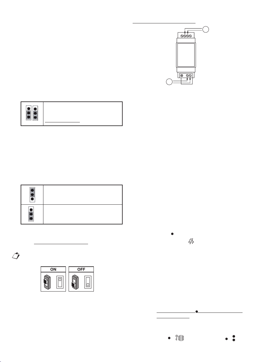
Le Dispositif de Renvoi d’Appel Multi-utilisateur est
fourni avec une alimentation locale Réf. 1083/24.
3. INSTALLATION DU
DISPOSITIF
L’installation du dispositif doit être effectuée par un
installateur de confiance.
Le dispositif doit être installé dans une colonne
conformément à la réglementation nationale en
vigueur.
Une connexion Internet est utilisée via un modem/
routeur ADSL ou 3G/4G par un câble Cat5/Cat5E
ou via une connexion Wi-Fi.
•
•
•
•
•
•
•
•
•
•
•
Le dispositif a été conçu pour une
utilisation résidentielle et ne permet
de configurer que certains paramètres
réseau ; pourtant il pourrait ne pas
fonctionner sur des configurations
spécifiques de réseaux IP d’entreprise.
Pour pouvoir recevoir l’appel, l’application Urmet
CallMe doit être installée sur un smartphone
connecté à Internet via une connexion de données
cellulaire ou Wi-Fi.
L’application Urmet CallMe permet également
d’utiliser :
la fonction d’intercom vers d’autres
smartphones connectés au même compte ;
la fonction d’auto-insertion (fonction
« Caméras » sur l’app CallMe) pour voir sur
le smartphone l’image filmée par les postes
externes (principaux et secondaires) et par
toute caméra de surveillance TVCC connectée
au poste externe ;
la fonction de liste des appels manqués.
L’application Urmet CallMe est également
essentielle pour la configuration du dispositif par
l’installateur et de la configuration du compte pour
l’utilisateur.
Le Dispositif de Renvoi d’Appel
fonctionne uniquement en supplément
des postes internes présents au sein de
l’appartement et est toujours configuré
comme s’il s’agissait d’un poste interne
avec ID/code correspondant à 3.
Le Dispositif de Renvoi d’Appel Multi-utilisateur
peut être installé selon l’un des modes suivants :
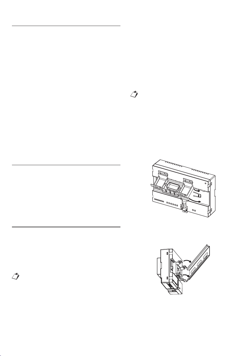
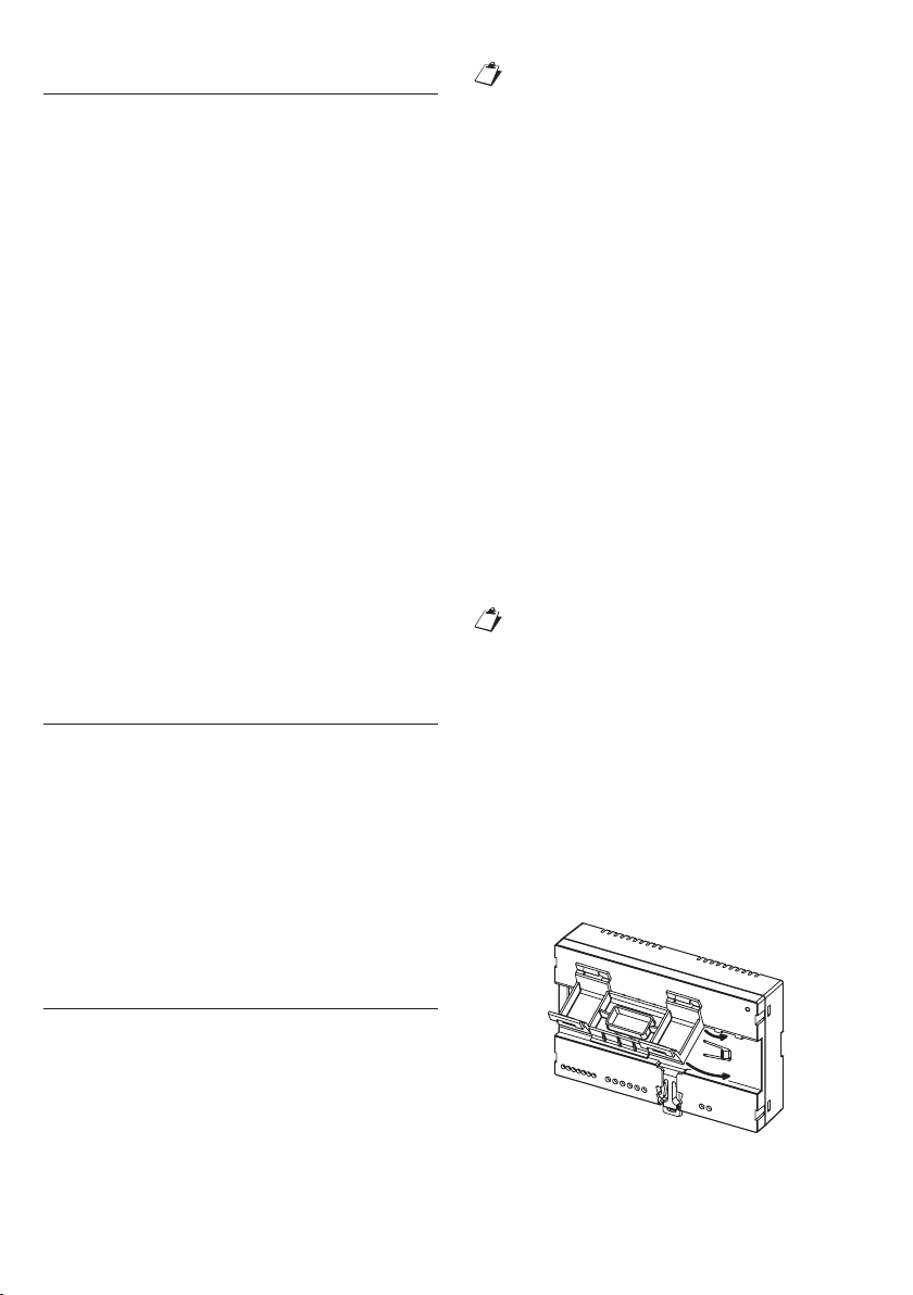
3.1. DANS UN TABLEAU
ÉLECTRIQUE
1. Inserire il distanziale dietro al dispositivo
nell’apposita sede, facendo in modo che venga
bloccato dalla leva A.
A
1
2
2. Mettre en place les crochets B de l’entretoise
dans le guide DIN de telle sorte que les borniers
du dispositif soient orientés vers le bas puis
mettre en place les crochets C.
1.
2.
3.