USBGEAR UTS-485 User manual

USB to RS-422 & RS-485 Adapter
-1-
USB TO RS-422 & RS-485 Adapter
User’s Manual
UTS-422 / UTS-485 / UTS-M12/UTS-M14-(DB-9 Connector)
UTS-422TB / UTS-485TB-(Terminal block Connector)
UTS-200J / UTS-200J2 / UTS-200J5-(RJ-11 Connector)

USB to RS-422 & RS-485 Adapter
-2-
Table of Contents
Introduction …………………………………………………………………..………….………….. 3
System Requirement
Features
Specifications
LED Indication
Pin-Assignment
Termination Resistor
Loopback
Win 98SE …………………….……………………………………….……………………..…………10
Installation
Uninstalling
Troubleshooting
Win 2000 ……………………………………………………………………………………..…………20
Installation
Uninstalling
Troubleshooting
Win CE ……………………………………………………………………….…………………….….. 29
Installation
Troubleshooting
Win XP ………………………………………………………..………………..……...………………. 36
Installation
Uninstalling
Troubleshooting
VISTA (Win 7 )………………………………………………………..……………,,….………… 48
Installation
Uninstalling
Troubleshooting
MAC ………………………………………………………………………………………,……………..57
Installation
Uninstalling
Troubleshooting
Regulatory Compliance …………………………….………………………………………,……….64

USB to RS-422 & RS-485 Adapter
-3-
Introduction
This Adapter is designed to make massive data communication become quick and simple through
an USB port of PC. By taking the advantage of the feature of USB port and Serial port, it provides
an easier and more convenient connectivity than ever for efficient and friendly interaction between
RS-422 or RS-485 devices and your computer systems.
The interface of RS-422 and RS-485 are very common adopted in data acquisition world. Both
standards feature reliable performance of full-duplex or half-duplex multi-drop communication
network with faster data rates and longer communication distance than RS-232. Application
devices include telecommunication units, LAN, data concentration, data multiplexers, ISDN, POS,
industrial controls, etc.
System Requirements
Windows Server 2000, 2008_2008R2_2003 x32_x64, Vista x32_x64, XP x32_x64, 7 x32_x64
Windows 98SE/ME/CE
Mac, Linux and higher,.
The system is equipped with USB Host Controller
Features
Reliable performance of full-duplex or half-duplex multi-drop communication
Fully compliant concurrent operation
Plug and play and hot-swapping
15KV ESD Protection
Supports data transmission at high rates over long distance(4,000ft.)
Supports devices include telecommunication units, LAN, data concentration, data
multiplexes, ISDN, POS, industrial controls, etc.
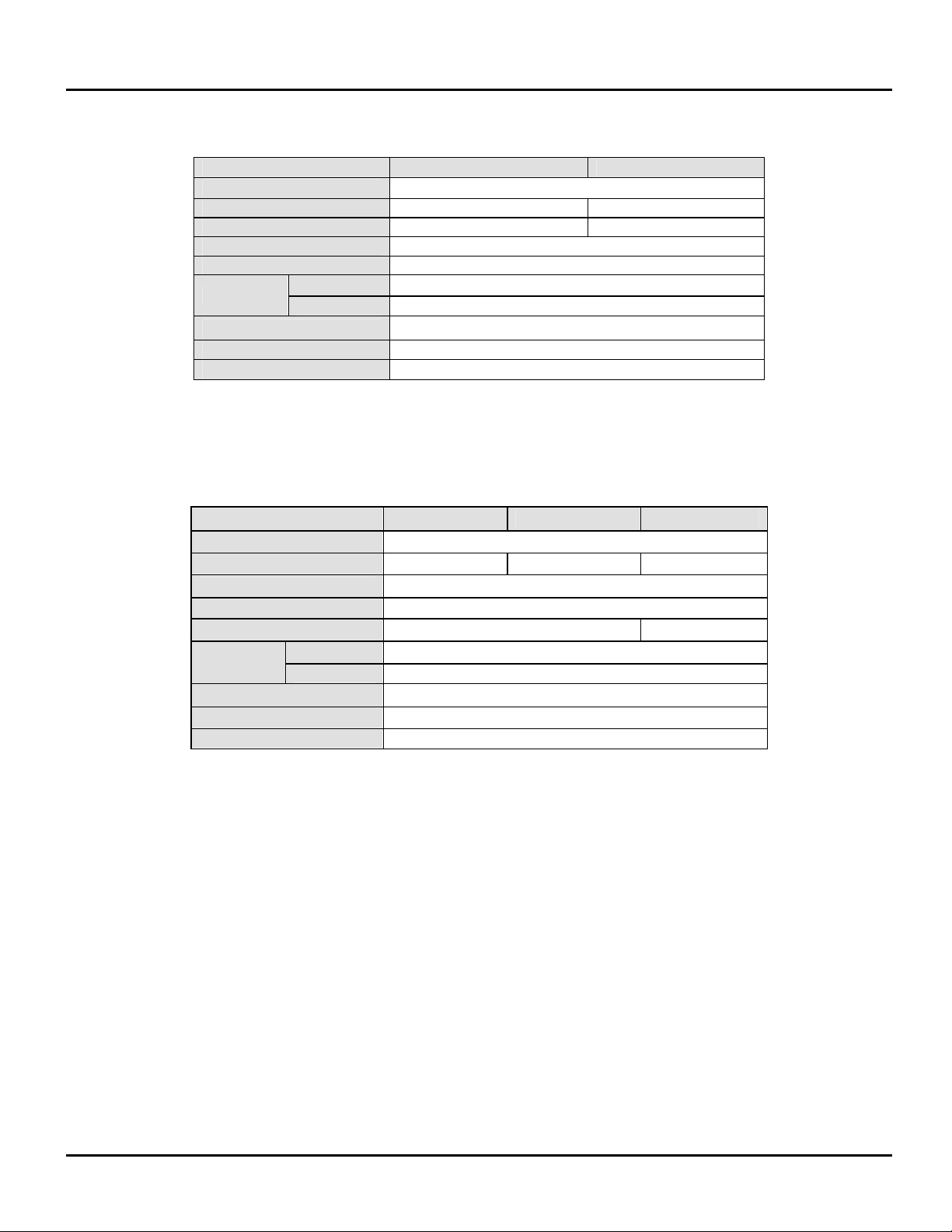
Specification:-
DB-9 Connector
Model No. UTS-485 UTS-422 UTS-M12 UTS-M14
Chipset FTDI
Interface RS-485 RS-422 RS-422/RS-485
Compliant USB Version USB 1.1 & 2.0
Data Speed 3 Mbps
Mode Selection Auto Slide Switch
Upstream USB A / M USB B / F
Connector Device DB-9 / M*1 DB-9/M*2 DB-9/ M*4
Power Mode Bus
Cable Length 1.1M 0.6M 1.8M
Housing PVC Molding Plastic Aluminum

USB to RS-422 & RS-485 Adapter
-4-
Terminal Block Connector
Model No. UTS-422TB UTS-485TB
Chipset FTDI
Device Interface RS-422 RS-485
Communication Mode Full-duplex-Multi-drop Half-duplex-Multi-drop
Compliant USB Version USB 1.1 & 2.0
Data Speed 3 Mbps
Upstream USB A / M
Connector Device Shield*1 and Terminal Block*4
Power Mode Bus
Cable Length 1M
Housing Plastic
RJ-11 Connector
Model No. UTS-200J2 UTS-200J5 UTS-200J
Chipset FTDI
Device Interface RS-422 RS-485 RS-422/RS-485
Compliant USB Version USB 1.1 & 2.0
Data Speed 3 Mbps
Selection Mode Auto Slide Switch
Upstream USB Type A Male
Connector Device RJ-11 4P phone jack/Female*2
Power Mode Bus
Cable Length 1M
Housing Plastic
LED light Indication
POWER/LINK--- unit is ready for use.
RX---Receive Data (Data is being sent from RS-422 or RS-485 device to USB port)
TX---Transmit Data (Data is being sent from USB port to RS-422 or RS-485 device).

USB to RS-422 & RS-485 Adapter
-5-
PIN Assignments
DB-9Connector
RS-422(DB-9M)
Pin# Description
1. TX-
2. TX+
3. RX+
4. RX-
5. GND
6. RTS-
7. RTS+
8. CTS+
9. CTS-
DB-9 DB-9
1 TX- RX- 4
2 TX+ RX+ 3
3 RX+ TX+ 2
4 RX- TX- 1
5 G G5
6 RTS- CTS- 9
7 RTS+ CTS+ 8
8 CTS+ RTS+ 7
9 CTS-
RTS- 6
RS-485(DB-9M)
Pin# Description
1. D+(TX)
2. D-(RX)
3.
4.
5. GND
6.
7.
8.
9.
DB-9 DB-9
1. D+(TX) D+(TX) 1
2 D-(RX) D-(RX) 2

USB to RS-422 & RS-485 Adapter
-6-
TerminalBlock
Pin# Definition Description
1. TX+
2. TX TX-
3. RX+
4. RX RX-
5. G GND
1 TX+ RX+ 3
2 TX- RX- 4
3 RX+ TX+ 1
4 RX- TX- 2
5 GND
GND 5
1. D+(TX) D+(TX) 1
2. D-(RX) D-(RX) 2
D+(TX) 3
D-(RX) 4
Pin# Definition Description
1. D+(TX)
2. 1 D-(RX)
3. D+(TX)
4. 2 D-(RX)
5. G GND
1 D+(TX)
2 D-(RX)
3 D+(TX) D+(TX) 3
4 D-(RX) D-(RX) 4
UTS-422TB
RX TX
G -+-+
5 4 3 2 1
UTS-485TB
2 1
G -+-+
5 4 3 2 1

USB to RS-422 & RS-485 Adapter
-7-
UTS-485TB
Termination Resistors :
Loopback
UTS-485TB Loopback
Jumper Pin J6 J7 Function Status
Setting Jumper
Plugged
Jumper
Un-Plugged OFF (Default)
Setting Jumper
Un-Plugged Jumper
Plugged ON
UTS-485TB Termination Resistor
120 Ω
Jumper Pin J1 Function Status
Setting Jumper Plugged ON (Default)
Setting Jumper Un-Plugged OFF

USB to RS-422 & RS-485 Adapter
-8-
RJ-11 Connector
RS-422 RS-485
Multi-Drop:
RS-422 (Full Duplex Mode)
PIN2 : RX+
PIN3 : RX-
PIN4 : TX-
PIN5 : TX+
RS-485 ( Half Duplex Mode)
PIN4 : D-(RX)
PIN5 : D+(TX)
Point to Point:
5
4PC# 1 PC# 2
2
3
5
4
2
3
RJ-11 RJ-11
TX+
TX-
RX+
RX-
TX+
TX-
RX+
RX-
PointtoPoint:
5
4
PC# 1 PC# 2
5
4
RJ-11 RJ-11
D+(TX)
D-(RX)
D+(TX)
D-(RX)
5
4
PC# 3 PC# 4
5
4
RJ-11 RJ-11
D+(TX)
D-(RX)
D+(TX
D-(RX)
5
4
PC# 1 PC# 2
5
4
RJ-11 RJ-11
D+(TX)
D-(RX)
D+(TX)
D-(RX)

USB to RS-422 & RS-485 Adapter
-9-
UTS-200J / UTS-200J5
Termination Resistors :
Loopback
N.B. Termination Resistors / Loopback alteration available for models shown only. Please
do not remove jumpers on other Models to avoid malfunction.
UTS-200J / UTS-200J5 Termination Resistor
120 Ω
Jumper Pin J1 J2
Function Status
Setting Jumper
Plugged
Jumper
Plugged ON (Default)
Setting Jumper
Un-Plugged Jumper
Un-Plugged OFF
UTS-200J / UTS-200J5 Loopback
Jumper Pin J6 J7
Function Status
Setting Jumper
Un-Plugged
Jumper
Plugged OFF (Default)
Setting Jumper
Plugged Jumper
UN-Plugged ON

USB to RS-422 & RS-485 Adapter
-10-
Windows 98SE Installation Guide
If a device of the same type has been installed on your machine before and the drivers that are about to be
installed are different from those installed already, the original drivers need to be uninstalled. Please refer to
the uninstalling instruction.
Download the latest available drivers from the FTDI website and unzip them to a location on your
PC.
Connect the device to a spare USB port on your PC. This will launch the Windows Add New
Hardware Wizard. Windows may display a message reading "Building driver database" at this point
which may take a few minutes to pass. Click "Next" to proceed with the installation.
Select "Search for the best driver for your device. (Recommended)." as shown below and then click "Next".

USB to RS-422 & RS-485 Adapter
-11-
· Check the box next to "Specify a location" and uncheck all others as shown below. Click "Browse" and
locate the driver files. Once the files have been located, click "Next" to proceed with the installation.
Windows may display a message reading "Building driver database" at this
point which may take a few minutes to pass. Once Windows has found the required files, click
"Next" to install the device.

USB to RS-422 & RS-485 Adapter
-12-
If the driver being installed does not have Microsoft WHQL signature files (.CAT files), the wizard will request
a driver disk to attempt to find them. Click "OK" on the "Insert Disk" message box.
The following window will appear to assist in locating the file. To proceed with the installation without
the .CAT file, click "Skip File".

USB to RS-422 & RS-485 Adapter
-13-
If the driver being installed is Microsoft WHQL certified, then the .CAT files will be located with the
other driver files and should be installed automatically.
Windows should then display a message indicating that the installation of the serial converter driver
was successful. The COM port emulation driver must now be installed. Click "Finish" to complete
the installation of the serial converter and proceed to the COM port emulation driver.
Under Windows 98SE, the COM port emulation driver will be automatically installed from the same location
as the serial converter driver. However, if the driver is not WHQL certified as explained above for the serial

USB to RS-422 & RS-485 Adapter
-14-
converter driver, the wizard will ask for the location of .CAT files. Click "OK" on the "Insert Disk" message
box.
The following window will appear to assist in locating the file. To proceed with the installation without
the .CAT file, click "Skip File".

USB to RS-422 & RS-485 Adapter
-15-
If the driver being installed is Microsoft WHQL certified, then the .CAT files will be located with the other
driver files and should be installed automatically.
Open the Device Manager (located in "Control Panel\System" then select the ""Device Manger" tab) and
select "View devices by type". The device appears as an additional COM port with the label "USB Serial
Port".
Please note:
1. For multiple-port converter, each port has to be installed with the driver individually, i.e.
you have to repeat this installation procedure 2 times (2-port converter) or 4 times (for
4-port converter).
2. If you have any
difficulties with the drivers we provided in this CD, you may download
the updated or appropriate versions from FTDI Web site
www.ftdichip.com/Drivers/VCP.htm, supported device “FT232BL(M)”.

USB to RS-422 & RS-485 Adapter
-16-
Uninstalling Instruction
To uninstall drivers, follow the instructions below:
Disconnect any devices that are attached to the PC.
Open the Add/Remove Programs utility located in "Control Panel\Add/Remove Programs". Select "FTDI
USB-Serial Converter Drivers" from the list of installed programs.
Click the "Add/Remove" button. This will run the FTDI uninstaller program. Click "Continue" to run the
uninstaller or "Cancel" to exit.

USB to RS-422 & RS-485 Adapter
-17-
When the uninstaller has finished removing the device from the system, the caption on the "Cancel" button
will change to "Finish". Click "Finish" to complete the process.

USB to RS-422 & RS-485 Adapter
-18-
Troubleshooting
1. Windows 98SE cannot find drivers for my device
This error can occur if the VID and PID programmed into the device EEPROM do not match those listed in
the INF files for the driver. The VID and PID programmed into the device EEPROM may be found by using
the USBView utility from the FTDI website. These can then be checked against the VID and PID entries in
the driver INF files. If they do not match, that driver cannot be installed the VID and PID entries in the driver
INF files. If they do not match, that driver cannot be installed for that device without either re-programming
the device EEPROM or modifying the list of VID and PID numbers in the INF files. Please note that only your
own company VID and PID or FTDI's VID (0x0403) and FTDI PID issued for use by your company should be
used in the EEPROM and INF/INI files.
2. Windows 98SE forces a reboot after installing a device
This problem can occur if an application is accessing a file while the New Hardware Wizard is trying to copy it.
This usually occurs with the FTD2XX.DLL file. If installing a D2XX device, selecting not to restart the
computer then unplugging and re-plugging the device may allow the device to function properly without
restarting. Restarting the machine will allow the device to work correctly.
3. Driver installation fails and Windows 98SE gives error code 10
Windows error code 10 indicates a hardware error or failed driver installation. This error may appear if a
device has insufficient power to operate correctly (e.g. plugged into a bus powered hub with other devices),
or may indicate a more serious hardware problem. Also, it may be indicative of USB root hub drivers being
incorrectly installed. Please refer to the example schematics on the FTDI website for standard device
configurations. If the error persists, please contact the FTDI support department.
4. Device hangs randomly during operation under Windows 98SE
This is not caused by the driver, but is a hardware compatibility problem. Some newer USB 2.0 hubs and
host controllers can be susceptible to noise and can cause random device failures. This can be overcome by
fitting 47pF capacitors to ground on the USBDP and USBDM lines on the USB connector side of the 27W
series resistors.
5. Windows 98SE complains about missing .CAT files
Files with the .cat extension are signature files issued by Microsoft that indicate a device driver is WHQL
certified. If a driver is not certified, there will be no .cat files available.
When installing drivers in Windows 98SE or Windows ME, the user is prompted to locate the .cat files if the
operating system cannot find them. If the driver is not certified but you wish to install it anyway, the files may
be skipped by clicking the "Skip" button.
6. Windows 98SE complains about missing ftccomms.vxd file

USB to RS-422 & RS-485 Adapter
-19-
This can occur when the USB Composite driver has been installed if the user has not browsed to the location
of the driver files. If this message appears, do not skip it but browse to the driver file location. The wizard will
then be able to correctly install the device.

USB to RS-422 & RS-485 Adapter
-20-
Windows 2000 Installation Guide
If a device of the same type has been installed on your machine before and the drivers that are
about to be installed are different from those installed already, the original drivers need to be
uninstalled. Please refer to the uninstalling instruction.
Download the latest available drivers from the FTDI web site and unzip them to a location on your
PC.
Connect the device to a spare USB port on your PC. Once the composite driver has been installed
the Found New Hardware Wizard will launch. Click "Next" to proceed with the installation.
Select "Search for a suitable driver for my device (recommended)" as shown
below and then click "Next".
This manual suits for next models
8
Table of contents
Other USBGEAR Adapter manuals