usi MS-01 User manual

MS-01 SOM Module
`
All rights are reserved by USI. No part of this technical document can be reproduced in any form without permission of USI.
Page 1
1. WiFi and Bluetooth
MS-01 Integrated Qualcomm WCN3990 to support WLAN 2x2 802.11a/b/g/n/ac with DBS and 160
MHz, Bluetooth 5.0.
n 2 × 2 802.11ac with MU-MIMO
n DBS support
n 160 MHz bandwidth support
n Bluetooth 5.0
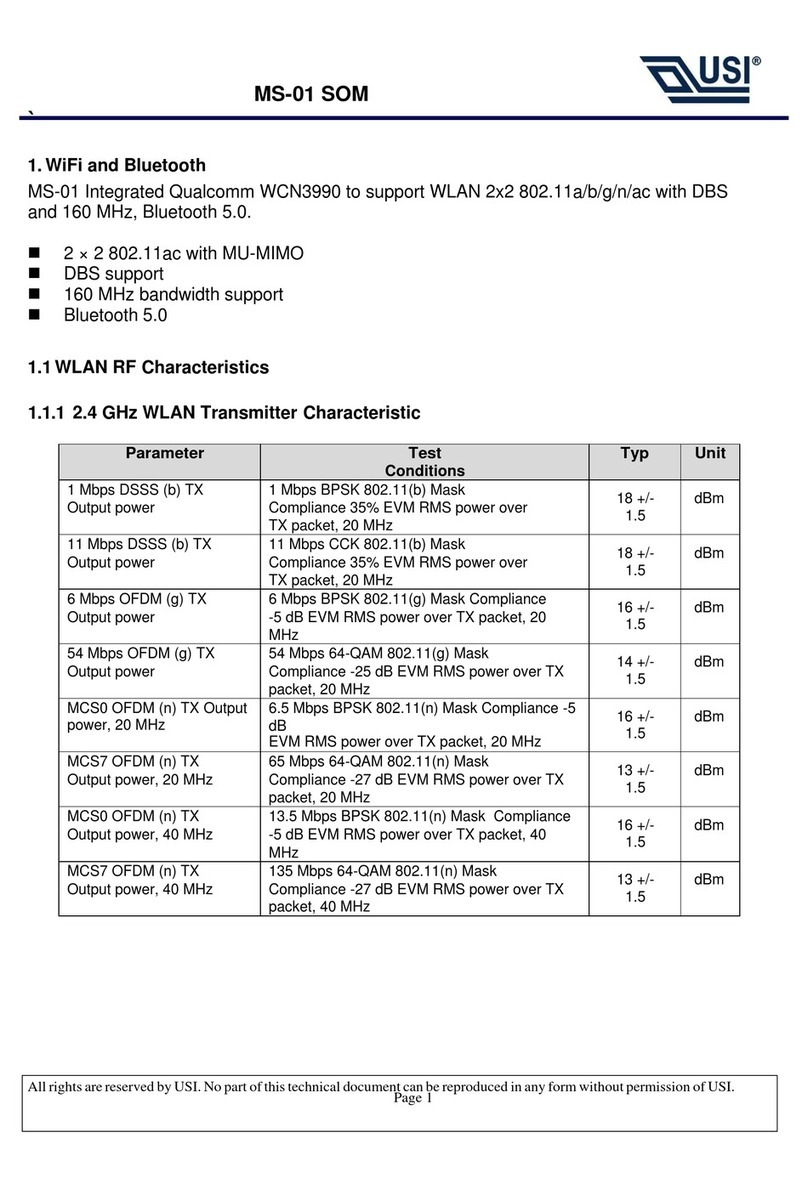
1.1 WLAN RF Characteristics
1.1.1 2.4 GHz WLAN Transmitter Characteristic
Parameter
Test Conditions
Typ
Unit
1 Mbps DSSS (b) TX Output
power
1 Mbps BPSK 802.11(b) Mask Compliance 35%
EVM RMS power over TX packet, 20 MHz
18 +/- 1.5
dBm
11 Mbps DSSS (b) TX Output
power
11 Mbps CCK 802.11(b) Mask Compliance 35%
EVM RMS power over TX packet, 20 MHz
18 +/- 1.5
dBm
6 Mbps OFDM (g) TX Output
power
6 Mbps BPSK 802.11(g) Mask Compliance -5 dB
EVM RMS power over TX packet, 20 MHz
16 +/- 1.5
dBm
54 Mbps OFDM (g) TX Output
power
54 Mbps 64-QAM 802.11(g) Mask Compliance -25
dB EVM RMS power over TX packet, 20 MHz
14 +/- 1.5
dBm
MCS0 OFDM (n) TX Output
power, 20 MHz
6.5 Mbps BPSK 802.11(n) Mask Compliance -5 dB
EVM RMS power over TX packet, 20 MHz
16 +/- 1.5
dBm
MCS7 OFDM (n) TX Output
power, 20 MHz
65 Mbps 64-QAM 802.11(n) Mask Compliance -27
dB EVM RMS power over TX packet, 20 MHz
13 +/- 1.5
dBm
MCS0 OFDM (n) TX Output
power, 40 MHz
13.5 Mbps BPSK 802.11(n) Mask Compliance -5 dB
EVM RMS power over TX packet, 40 MHz
16 +/- 1.5
dBm
MCS7 OFDM (n) TX Output
power, 40 MHz
135 Mbps 64-QAM 802.11(n) Mask Compliance -27
dB EVM RMS power over TX packet, 40 MHz
13 +/- 1.5
dBm

MS-01 SOM Module
`
All rights are reserved by USI. No part of this technical document can be reproduced in any form without permission of USI.
Page 2
1.1.2 2.4 GHz WLAN Receiver Characteristic
Parameter
Test Conditions
Min
Typ
Max
Unit
1 Mbps DSSS (b) Rx Sensitivity
8% PER, 20 MHz
-
-96
-
dBm
11 Mbps DSSS (b) Rx Sensitivity
8% PER, 20 MHz
-
-88
-
dBm
6 Mbps OFDM (g) Rx Sensitivity
10% PER, 20 MHz
-
-91
-
dBm
54 Mbps OFDM (g) Rx Sensitivity
10% PER, 20 MHz
-
-74
-
dBm
MCS0 OFDM (n) Rx Sensitivity
10% PER, 20 MHz
-
-91
-
dBm
MCS7 OFDM (n) Rx Sensitivity
10% PER, 20 MHz
-
-71
-
dBm
MCS0 OFDM (n) Rx Sensitivity
10% PER, 40 MHz
-
-88
-
dBm
MCS7 OFDM (n) Rx Sensitivity
10% PER, 40 MHz
-
-69
-
dBm
802.11b RX Overload Level - 20MHz
8% PER, 11 Mbps
-10
-
-
-
802.11g RX Overload Level - 20MHz
10% PER, 54 MHz
-20
-
-
-
802.11n RX Overload Level - 20MHz
10% PER, MCS7
-20
-
-
-
1.1.3 5 GHz WLAN Transmitter Characteristics
Parameter
Test Conditions
Typ
Unit
6 Mbps OFDM (a) TX Output power
6 Mbps BPSK 802.11(a) Mask Compliance -5 dB
EVM RMS power over TX packet, 20 MHz
16 +/- 1.5
dBm
54 Mbps OFDM (a) TX Output power
54 Mbps 64-QAM 802.11(a) Mask Compliance -
25 dB EVM RMS power over TX packet, 20 MHz
14 +/- 1.5
dBm
MCS0 OFDM (n) TX Output power, 20 MHz
6.5 Mbps BPSK 802.11(n) Mask Compliance -5
dB EVM RMS power over TX packet, 20 MHz
16 +/- 1.5
dBm
MCS7 OFDM (n) TX Output power, 20 MHz
65 Mbps 64-QAM 802.11(n) Mask Compliance -
27 dB EVM RMS power over TX packet, 20 MHz
13 +/- 1.5
dBm
MCS0 OFDM (n) TX Output power, 40 MHz
13.5 Mbps BPSK 802.11(n) Mask Compliance -5
dB EVM RMS power over TX packet, 40 MHz
16 +/- 1.5
dBm
MCS7 OFDM (n) TX Output power, 40 MHz
135 Mbps 64-QAM 802.11(n) Mask Compliance -
27 dB EVM RMS power over TX packet, 40 MHz
13 +/- 1.5
dBm
MCS0 OFDM (ac) TX Output power, 20
MHz
BPSK 802.11(ac) Mask Compliance -5 dB EVM
RMS power over TX packet, 20 MHz
16 +/- 1.5
dBm
MCS8 OFDM (ac) TX Output power, 20
MHz
64-QAM 802.11(ac) Mask Compliance -30 dB
EVM RMS power over TX packet, 20 MHz
12 +/- 1.5
dBm
MCS0 OFDM (ac) TX Output power, 40
MHz
13.5 Mbps BPSK 802.11(ac) Mask Compliance -5
dB EVM RMS power over TX packet, 40 MHz
16 +/- 1.5
dBm
MCS9 OFDM (ac) TX Output power, 40
MHz
180 Mbps 256-QAM 802.11(ac) Mask
Compliance -32 dB EVM RMS power over TX
packet, 40 MHz
11 +/- 1.5
dBm
MCS0 OFDM (ac) TX Output power, 80
MHz
29.3 Mbps BPSK 802.11(ac) Mask Compliance -5
dB EVM RMS power over TX packet, 80 MHz
16 +/- 1.5
dBm
MCS9 OFDM (ac) TX Output power, 80
MHz
390 Mbps 256-QAM 802.11(ac) Mask
Compliance -32 dB EVM RMS power over TX
packet, 40 MHz
11 +/- 1.5
dBm

MS-01 SOM Module
`
All rights are reserved by USI. No part of this technical document can be reproduced in any form without permission of USI.
Page 3
1.1.4 5 GHz WLAN Receiver Characteristics
1. Parameter
Test Conditions
Min
Typ
Max
Unit
6 Mbps OFDM (a) Rx Sensitivity
10% PER, 20 MHz
-
-92
-
dBm
54 Mbps OFDM (a) Rx Sensitivity
10% PER, 20 MHz
-
-75
-
dBm
MCS0 OFDM (n) Rx Sensitivity
10% PER, 20 MHz
-
-91
-
dBm
MCS7 OFDM (n) Rx Sensitivity
10% PER, 20 MHz
-
-73
-
dBm
MCS0 OFDM (n) Rx Sensitivity
10% PER, 40 MHz
-
-88
-
dBm
MCS7 OFDM (n) Rx Sensitivity
10% PER, 40 MHz
-
-70
-
dBm
MCS0 OFDM (ac) Rx Sensitivity
10% PER, 20 MHz
-
-91
-
dBm
MCS8 OFDM (ac) Rx Sensitivity
10% PER, 20 MHz
-
-68
-
dBm
MCS0 OFDM (ac) Rx Sensitivity
10% PER, 40 MHz
-
-88
-
dBm
MCS9 OFDM (ac) Rx Sensitivity
10% PER, 40 MHz
-
-64
-
dBm
MCS0 OFDM (ac) Rx Sensitivity
10% PER, 80 MHz
-
-84
-
dBm
MCS9 OFDM (ac) Rx Sensitivity
10% PER, 80 MHz
-
-59
-
dBm
2. Bluetooth RF Characteristics
MS-01 Integrated Qualcomm WCN3990 to Support Bluetooth 5.0 and is backwards compatible with
previous BT standard revisions.
2.1 Bluetooth RF Characteristics
The following tables show the Bluetooth transmitting and receiving performance
Transmitter Performance
Packet Types
DH5
2-DH5
3-DH5
Transmitting Power
11 +/- 1.5 dB
8 +/- 1.5 dB
8 +/- 1.5 dB
Receiver Performance
Packet Types
DH5
2-DH5
3-DH5
Receiving Sensitivity
-93 dBm
-93 dBm
-86 dBm

MS-01 SOM Module
`
All rights are reserved by USI. No part of this technical document can be reproduced in any form without permission of USI.
Page 4
OEM/Integrators Installation Manual
Important Notice to OEM integrators
1. This module is limited to OEM installation ONLY.
2. This module is limited to installation in mobile or fixed applications, according to Part 2.1091(b).
3. The separate approval is required for all other operating configurations, including portable
configurations with respect to Part 2.1093 and different antenna configurations
4. For FCC Part 15.31 (h) and (k): The host manufacturer is responsible for additional testing to verify
compliance as a composite system. When testing the host device for compliance with Part
15 Subpart B, the host manufacturer is required to show compliance with Part 15 Subpart B while the
transmitter module(s) are installed and operating. The modules should be transmitting and the
evaluation should confirm that the module's intentional emissions are compliant (i.e. fundamental
and out of band emissions). The host manufacturer must verify that there are no additional
unintentional emissions other than what is permitted in Part 15 Subpart B or emissions are complaint
with the transmitter(s) rule(s).
Antenna Installation
(1) The antenna must be installed such that 20 cm is maintained between the antenna and users,
(2) The transmitter module may not be co-located with any other transmitter or antenna.
(3) To comply with FCC/IC regulations limiting both maximum RF output power and human exposure
to RF radiation, the maximum antenna gain including cable loss in a mobile exposure condition must
not exceed:
Standalone Condition:
。 1.44 dBi in 2.4 GHz Band
。 2.16 dBi in 5.2GHz Band
。 2.16 dBi in 5.3GHz Band
。 2.16 dBi in 5.5GHz Band
。 2.16 dBi in 5.8GHz Band
In the event that these conditions cannot be met (for example certain laptop configurations or co-
location with another transmitter), then the FCC/IC authorization is no longer considered valid and
the FCC ID/IC ID cannot be used on the final product. In these circumstances, the OEM integrator will
be responsible for re-evaluating the end product (including the transmitter) and obtaining a separate
FCC/IC authorization.

MS-01 SOM Module
`
All rights are reserved by USI. No part of this technical document can be reproduced in any form without permission of USI.
Page 5
Federal Communication Commission Interference Statement
This device complies with Part 15 of the FCC Rules. Operation is subject to the following two
conditions: (1) This device may not cause harmful interference, and (2) this device must
accept any interference received, including interference that may cause undesired operation.
This equipment has been tested and found to comply with the limits for a Class B digital
device, pursuant to Part 15 of the FCC Rules. These limits are designed to provide reasonable
protection against harmful interference in a residential installation. This equipment generates,
uses and can radiate radio frequency energy and, if not installed and used in accordance with
the instructions, may cause harmful interference to radio communications. However, there is
no guarantee that interference will not occur in a particular installation. If this equipment
does cause harmful interference to radio or television reception, which can be determined by
turning the equipment off and on, the user is encouraged to try to correct the interference by
one of the following measures:
- Reorient or relocate the receiving antenna.
- Increase the separation between the equipment and receiver.
- Connect the equipment into an outlet on a circuit different from that
to which the receiver is connected.
- Consult the dealer or an experienced radio/TV technician for help.
FCC Caution: Any changes or modifications not expressly approved by the party responsible
for compliance could void the user's authority to operate this equipment.
This transmitter must not be co-located or operating in conjunction with any other antenna or
transmitter.
Radiation Exposure Statement:
This equipment complies with FCC radiation exposure limits set forth for an uncontrolled
environment. This equipment should be installed and operated with minimum distance 20cm
between the radiator & your body.

MS-01 SOM Module
`
All rights are reserved by USI. No part of this technical document can be reproduced in any form without permission of USI.
Page 6
This device is intended only for OEM integrators under the following conditions:
1) The antenna must be installed such that 20 cm is maintained between the antenna and
users, and
2) The transmitter module may not be co-located with any other transmitter or antenna.
As long as 2 conditions above are met, further transmitter test will not be required. However,
the OEM integrator is still responsible for testing their end-product for any additional
compliance requirements required with this module installed
IMPORTANT NOTE: In the event that these conditions can not be met (for example certain
laptop configurations or co-location with another transmitter), then the FCC authorization is
no longer considered valid and the FCC ID can not be used on the final product. In these
circumstances, the OEM integrator will be responsible for re-evaluating the end product
(including the transmitter) and obtaining a separate FCC authorization.
End Product Labeling
This transmitter module is authorized only for use in device where the antenna may be
installed such that 20 cm may be maintained between the antenna and users. The final end
product must be labeled in a visible area with the following: “Contains FCC ID: COF-MS01”.
The grantee's FCC ID can be used only when all FCC compliance requirements are met.
Manual Information To the End User
The OEM integrator has to be aware not to provide information to the end user regarding
how to install or remove this RF module in the user’s manual of the end product which
integrates this module.
The end user manual shall include all required regulatory information/warning as show in this
manual.

MS-01 SOM Module
`
All rights are reserved by USI. No part of this technical document can be reproduced in any form without permission of USI.
Page 7
This device is intended only for OEM integrators under the following conditions:
1) The antenna must be installed with 20 cm is maintained between the antenna and users in
mobile or fixed applications.
2) The Antenna for Module (MS-01) is Non-detachable and the maximum antenna gain allowed
for use with this device is 1.44 [email protected] band & 2.16dBi@5GHz band.
3) The transmitter module may not be co-located with any other transmitter or antenna.
4) OEM integrators Must demonstrate SAR test and meet compliance before end-product with
module (MS-01) marketed in portable application.
As long as 2 conditions above are met, further transmitter test will not be required. However, the
OEM integrator is still responsible for testing their end-product for any additional compliance
requirements required with this module installed.
OEM integrators Must demonstrate Part 15B test and meet compliance before end-product with
module (MS-01) marketed.
US Information
Name of the company: USI America, Inc
Address of the company: 2000 Regency Parkway, Suite 420, Cary, NC 27518
Phone number: 919-466-8688 Ext. 109
General
The SOM module uses Dipole antenna to do EMC official test then antenna gain and trace design,
please refer to antenna information and antenna trace design.
Antenna Information
Antenna Type: Dipole
Antenna gain: 1.44dBi@2.4GHz and 2.16dBi@5GHz

MS-01 SOM Module
`
All rights are reserved by USI. No part of this technical document can be reproduced in any form without permission of USI.
Page 8
Antenna Trace Design
WLAN chain0/BT
Top layer
WLAN chain1
Top layer

MS-01 SOM Module
`
All rights are reserved by USI. No part of this technical document can be reproduced in any form without permission of USI.
Page 9
Industry Canada statement:
This device complies with ISED’s licence-exempt RSSs. Operation is subject to the following two
conditions: (1) This device may not cause harmful interference, and (2) this device must accept any
interference received, including interference that may cause undesired operation.
Le présent appareil est conforme aux CNR d’ ISED applicables aux appareils radio exempts de licence.
L’exploitation est autorisée aux deux conditions suivantes : (1) le dispositif ne doit pas produire de
brouillage préjudiciable, et (2) ce dispositif doit accepter tout brouillage reçu, y compris un brouillage
susceptible de provoquer un fonctionnement indésirable.
Radiation Exposure Statement:
This equipment complies with ISED radiation exposure limits set forth for an uncontrolled
environment. This equipment should be installed and operated with minimum distance 20cm
between the radiator & your body.
Déclaration d'exposition aux radiations:
Cet équipement est conforme aux limites d'exposition aux rayonnements ISED établies pour un
environnement non contrôlé. Cet équipement doit être installé et utilisé avec un minimum de 20 cm
de distance entre la source de rayonnement et votre corps.

MS-01 SOM Module
`
All rights are reserved by USI. No part of this technical document can be reproduced in any form without permission of USI.
Page 10
This device is intended only for OEM integrators under the following conditions: (For module device use)
1) The antenna must be installed such that 20 cm is maintained between the antenna and users, and
2) The transmitter module may not be co-located with any other transmitter or antenna.
As long as 2 conditions above are met, further transmitter test will not be required. However, the
OEM integrator is still responsible for testing their end-product for any additional compliance
requirements required with this module installed.
Cet appareil est conçu uniquement pour les intégrateurs OEM dans les conditions suivantes: (Pour
utilisation de dispositif module)
1) L'antenne doit être installée de telle sorte qu'une distance de 20 cm est respectée entre l'antenne
et les utilisateurs, et
2) Le module émetteur peut ne pas être coïmplanté avec un autre émetteur ou antenne.
Tant que les 2 conditions ci-dessus sont remplies, des essais supplémentaires sur l'émetteur ne
seront pas nécessaires. Toutefois, l'intégrateur OEM est toujours responsable des essais sur son
produit final pour toutes exigences de conformité supplémentaires requis pour ce module installé.
IMPORTANT NOTE:
In the event that these conditions can not be met (for example certain laptop configurations or co-
location with another transmitter), then the Canada authorization is no longer considered valid and
the IC ID can not be used on the final product. In these circumstances, the OEM integrator will be
responsible for re-evaluating the end product (including the transmitter) and obtaining a separate
Canada authorization.
NOTE IMPORTANTE:
Dans le cas où ces conditions ne peuvent être satisfaites (par exemple pour certaines configurations
d'ordinateur portable ou de certaines co-localisation avec un autre émetteur), l'autorisation du
Canada n'est plus considéré comme valide et l'ID IC ne peut pas être utilisé sur le produit final. Dans
ces circonstances, l'intégrateur OEM sera chargé de réévaluer le produit final (y compris l'émetteur)
et l'obtention d'une autorisation distincte au Canada.
End Product Labeling
This transmitter module is authorized only for use in device where the antenna may be installed such
that 20 cm may be maintained between the antenna and users. The final end product must be
labeled in a visible area with the following: “Contains IC:10293A-MS01”.

MS-01 SOM Module
`
All rights are reserved by USI. No part of this technical document can be reproduced in any form without permission of USI.
Page 11
Plaque signalétique du produit final
Ce module émetteur est autorisé uniquement pour une utilisation dans un dispositif où l'antenne
peut être installée de telle sorte qu'une distance de 20cm peut être maintenue entre l'antenne et les
utilisateurs. Le produit final doit être étiqueté dans un endroit visible avec l'inscription suivante:
"Contient des IC: 10293A-MS01 ".
Manual Information To the End User
The OEM integrator has to be aware not to provide information to the end user regarding how to
install or remove this RF module in the user’s manual of the end product which integrates this
module.
The end user manual shall include all required regulatory information/warning as show in this
manual.
Manuel d'information à l'utilisateur final
L'intégrateur OEM doit être conscient de ne pas fournir des informations à l'utilisateur final quant à
la façon d'installer ou de supprimer ce module RF dans le manuel de l'utilisateur du produit final qui
intègre ce module.
Le manuel de l'utilisateur final doit inclure toutes les informations réglementaires requises et
avertissements comme indiqué dans ce manuel.

MS-01 SOM Module
`
All rights are reserved by USI. No part of this technical document can be reproduced in any form without permission of USI.
Page 12
RSS-247 Section 6.4 (5) (6) (for local area network devices, 5GHz)
The device could automatically discontinue transmission in case of absence of information to
transmit, or operational failure. Note that this is not intended to prohibit transmission of control or
signaling information or the use of repetitive codes where required by the technology.
The device for operation in the band 5150–5250 MHz is only for indoor use to reduce the potential
for harmful interference to co-channel mobile satellite systems;
The maximum antenna gain permitted for devices in the bands 5250–5350 MHz and 5470–5725 MHz
shall comply with the e.i.r.p. limit; and
The maximum antenna gain permitted for devices in the band 5725–5825 MHz shall comply with the
e.i.r.p. limits specified for point-to-point and non point-to-point operation as appropriate.
L'appareil peut interrompre automatiquement la transmission en cas d'absence d'informations à
transmettre ou de panne opérationnelle. Notez que ceci n'est pas destiné à interdire la transmission
d'informations de contrôle ou de signalisation ou l'utilisation de codes répétitifs lorsque cela est
requis par la technologie.
Le dispositif utilisé dans la bande 5150-5250 MHz est réservé à une utilisation en intérieur afin de
réduire le risque de brouillage préjudiciable aux systèmes mobiles par satellite dans le même canal;
Le gain d'antenne maximal autorisé pour les dispositifs dans les bandes 5250-5350 MHz et 5470-5725
MHz doit être conforme à la norme e.r.p. limite; et
Le gain d'antenne maximal autorisé pour les appareils de la bande 5725-5825 MHz doit être
conforme à la norme e.i.r.p. les limites spécifiées pour un fonctionnement point à point et non point
à point, selon le cas.

MS-01 SOM Module
`
All rights are reserved by USI. No part of this technical document can be reproduced in any form without permission of USI.
Page 13
CE RF exposure
RF Exposure Information (MPE)
This device has been tested and meets applicable limits for Radio Frequency (RF) exposure. To
comply with the RF exposure requirements, this module must be installed in a host platform that is
intended to be operated in a minimum of 20 cm separation distance to the user.
Hereby, USI declares that the radio equipment type WiFi SOM Module is in compliance with Directive
2014/53/EU.
The full text of the EU declaration of conformity is available at the following internet address:
https://www.usiglobal.com/tw/MS-01/DoC.pdf
In all cases assessment of the final product must be met against the Essential requirements of the RE
Directive Articles 3.1(a) and (b), safety and EMC respectively, as well as any relevant Article 3.3
requirements.
1. The Dipole antenna (WLAN/BT: 1.44dBi@2.4GHz,2.16dBi@5GHz) was verified in the conformity
testing, and for compliance the antenna shall not be modified. A separate approval is required for all
other operating configurations, including different antenna configurations.
2. If any other simultaneous transmission radio is installed in the host platform together with this
module, or above restrictions cannot be kept, a separate RF exposure assessment and CE equipment
certification is required.
The device is restricted to indoor use only when operating in the 5150 to 5350 MHz frequency range.
AT
BE
BG
HR
CY
CZ
DK
EE
FI
FR
DE
EL
HU
IE
IT
LV
LT
LU
MT
NL
PL
PT
RO
SK
SI
ES
SE
UK
Table of contents
Other usi Computer Hardware manuals
Popular Computer Hardware manuals by other brands

Sony
Sony BKPF-L752 Maintenance manual

CNC4PC
CNC4PC C25 user manual

HPE
HPE FlexFabric 12900E LSXM1TGS24QGMODHB1 quick start guide

FirmTek
FirmTek SeriTek /e6G user manual

ZyXEL Communications
ZyXEL Communications ZyXEL ZyAIR B-120 Quick installation guide

Phytec
Phytec phyCORE-LPC3180 Quick start instructions

TECOM
TECOM A335W user manual

ETAS
ETAS FETK-T4.0B user guide

ekwb
ekwb EK-XRES DCP 4.0 INSTALLATION AND MOUNTING MANUAL

Middle Atlantic Products
Middle Atlantic Products ESSEX FANTOP-138DC instruction sheet

EK-Quantum
EK-Quantum Vector Master RTX 4090 D-RGB user guide

Acrosser Technology
Acrosser Technology AR-ES5495 installation guide