USOUND TARVOS 1.0 UC-E3010 User manual

Tarvos evaluation board 1.0 UC-E3010 | User Manual
NDA required | Released in March 2023
EVALUATION BOARD
FOR ASIC LINEAR AMPLIFIER
TARVOS EVALUATION BOARD 1.0 UC-E3010
USER MANUAL
Tarvos evaluation board 1.0 UC-E3010
provides the access to the key features of the
ASIC linear audio amplifier Tarvos 1.0
UC P3010. It allows acoustical performance
measurements of Usound MEMS speakers in
combination with the Carme kits.
Tarvos 1.0 UC-P3010 is included in the Tarvos
evaluation board 1.0 with default
configuration to provide optimized
performance of the USound MEMS speakers.
FEATURES
■
Pre-configurated for Conamara or Ganymede
MEMS speaker series
■
Selectable gain settings 18, 24, 30 dB
■
Compatible with Carme kits for acoustical
measurements
■
Power consumption measurements

2
Tarvos evaluation board 1.0 UC-E3010 | User Manual
NDA required | Released in March 2023
CONTENTS
OVERVIEW 3
QUICK START GUIDE 4
OPERATING CONDITIONS 5
EVALUATION BOARD SCHEMATIC 5
CONNECTIONS 6
APPENDIX 1 - POWER CONSUMPTION MEASUREMENTS PROCEDURE 7
APPENDIX 2 –BILL OF MATERIAL 10
REVISION HISTORY:
March 2023: First release

3
Tarvos evaluation board 1.0 UC-E3010 | User Manual
NDA required | Released in March 2023
OVERVIEW
Tarvos evaluation board 1.0, UC-E3010, allows testing of performance and key features of Tarvos 1.0
ASIC linear audio amplifier UC-P3010. Tarvos 1.0 UC-P3010 is a high-voltage linear audio amplifier
with integrated DC-DC boost converter. The device can provide up to 28 VPP and draws 0.8 mA of
quiescent current, or 0.5 μA when Tarvos 1.0 UC-P3010 is disabled, from a 3.6 V supply.
It’s features a differential input, programmable gain, DC/DC boost converter (VBST ), and DC bias (VBP)
to fully optimize the performance of USound MEMS speakers depending on the application. Therefore,
Tarvos 1.0 UC-P3010 is provided on the Tarvos evaluation board 1.0 UC-E3010 with the
corresponding default configuration.
Default configuration Tarvos 1.0 UC-P3010 for Conamara series:
•Gain 18 dB
•DC-DC Boost VBST=11 V, MEMS speaker VDC BIAS=11 V
Default configuration Tarvos 1.0 UC-P3010 for Ganymede series:
•Gain 24 dB
•DC-DC Boost VBST=14 V, MEMS speaker VDC BIAS=14 V
Further customization of the configuration can be done through a I2C master device.
Ordering product codes
UC-E3010-C00
Tarvos Evaluation Board 1.0 with default configuration for Conamara series
(UA-C0501-2T, UA-C0601-2F, UA-C0601-2T)
UC-E3010-G00
Tarvos Evaluation Board 1.0 with default configuration for Ganymede series
(UT-P2023, UT-P2020, UT-P2016)
Table 1. Ordering product codes
Tarvos evaluation board 1.0 UC-E3010 is shown in Figure 1. It can be supplied with an external power
supply (2.7 V ≤ V BAT ≤ 5.0 V) and an audio signal source.
Additionally, the evaluation board enables the user to perform acoustical measurements of USound
MEMS speakers in combination with Usound measurement adapters Carme kit: UJ-E1040C06 for
Conamara 6 mm, UJ-E1040C05 for Conamara 5 mm or UJ-E1040G00 for Ganymede series.

4
Tarvos evaluation board 1.0 UC-E3010 | User Manual
NDA required | Released in March 2023
Figure 1. Tarvos evaluation board 1.0 UC-E3010 top view
QUICK START GUIDE
1. Drive enable (EN) of J6 to GND for starting with a disabled Tarvos evaluation board 1.0
UC-P3010.
2. Connect the load (i.e. Conamara or Ganymede MEMS speakers) across OUTP (J11) and OUTN
(J7). The Carme kits (UJ-E1040G00, UJ-E1040C05, UJ-E1040C06) can be directly connected
to these headers.
3. Connect a power supply (2.7 V ≤ VBAT ≤ 5.0 V) and ground reference, respectively to VBAT
and GND headers on the evaluation board.
4. Connect a differential audio input to either INN and INP (including a low pass filter) or to J5-2
and J4-2 (without including the low pass filter). The latter is recommended when using Audio
Instrumentations (i.e. Audio Precision, SoundCheck, etc.).
5. Drive enable (EN) of J6 to VBAT for normal operation.
6. Power on the board
7. Provide the audio input signal and measure the output on OUTN and OUTP.
DON’TS
•Do not connect or disconnect wires to the audio inputs INP, INN while the device enabled.
Always drive EN low before connecting the signal generator.
•Do not connect and disconnect the output load (speaker) while the audio signal is applied.
•Hard clipping of the audio signal (amplitude too high) must be avoided.
•Square wave input signal is not allowed
•Do not send any I2C commands without support from Usound

5
Tarvos evaluation board 1.0 UC-E3010 | User Manual
NDA required | Released in March 2023
OPERATING CONDITIONS
Table 2shows the operating temperature and supply voltage ranges for Tarvos evaluation board 1.0
UC-E3010.
Operating Conditions
Temperature range: (TMIN ≤ TA≤ TMAX)
-20⁰ C ≤ TA≤ 85⁰ C
Supply Voltage (VBAT )
2.7 V ≤ VBAT ≤ 5.0 V
Table 2. Tarvos evaluation board 1.0 UC-E3010 operating conditions
EVALUATION BOARD SCHEMATIC
Figure 2. Tarvos evaluation board 1.0 UC-E3010 schematic

6
Tarvos evaluation board 1.0 UC-E3010 | User Manual
NDA required | Released in March 2023
CONNECTIONS
Table 3 displays all the connections available on the Tarvos evaluation board 1.0 UC-E3010.
Designator
Function
Notes
J2
VBAT
Power supply, positive terminal
J3
GND
Power supply, negative terminal
J4
INP –HEADER
J4 allows separation of INP (J15) and a low pass filter stage
(cut-off frequency at 30kHz) from the coupling capacitor C.
If the low pass filter is desired, short J4-1 and J4-2, and
apply the positive audio signal to J15 (INP).
If the low pass filter is not desired ensure there is not any
contact between J4-1 and J4-2 and connect the positive
audio signal to J4-2 (TP12).
J5
INN –HEADER
J5 allows separation of INP (J8) and a low pass filter stage
(cut-off frequency at 30kHz) from the coupling capacitor C9.
If the low pass filter is desired, short J5-1 and J5-2, and
apply the positive audio signal to J8 (INP).
If the low pass filter is not desired ensure there is not any
contact between J5-1 and J5-2 and connect the positive
audio signal to J5-2 (TP13).
J6
ENABLE
Active High Enable. Drive EN low to disable the device.
Connect EN to VBAT for normal operation.
J7
OUTN
Negative audio output terminal (to be connected to MEMS
speaker negative electrode)
J8
INN
Negative audio input terminal with a following low pass
filter stage (cut-off frequency at 30 kHz)
J9
VEXT
External digital supply for pulling up the I2C lines with R5
(not assembled) and R6 (not assembled) to the digital supply
domain
J11
OUTP
Positive audio output terminal (to be connected to MEMS
speaker positive electrode)
J13
I2C SDA/SCL/GND
I2C terminals SDA, SCL and GND for connection to an I2C
Master
J15
INP
Positive audio input terminal with a following low pass filter
stage (cut-off frequency at 30 kHz)
J18
GND
Ground connections for instrumentation references
Table 3. Tarvos evaluation board 1.0 UC-E3010 connections

7
Tarvos evaluation board 1.0 UC-E3010 | User Manual
NDA required | Released in March 2023
APPENDIX 1 - POWER CONSUMPTION MEASUREMENTS
PROCEDURE
USound MEMS speakers have a frequency dependent impedance (showing a capacitance behaviour),
so the power consumption is strongly dependent on the frequency of the signal. Therefore, only power
consumption measurements such as the quiescent current from a certain power supply can be taken
from a static DC current measurement instrument (i.e. Multimeter).
In order to provide a more accurate power consumption measurement within the context of the
application (i.e. audio playback), various measurement signals (i.e. IEC Noise 60268-1) are used and
the average of the power consumption over time must be taken.
HARDWARE MEASUREMENT SETUP
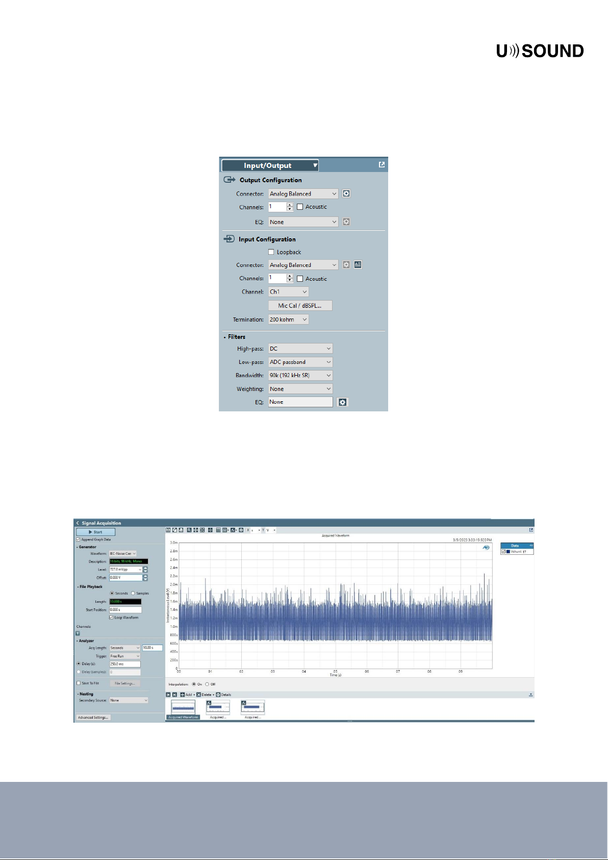
Power consumption measurements with audio playback can be carried out with the appropriate
instrumentation (with enough sampling frequency, low enough noise floor, enough sensitivity and
range, etc.). Instrumentation used for measuring audio signals (for example: Audio Precision
instrumentation) usually provide the means necessary to also perform such power consumption
measurements. Therefore, an Audio Precision instrument is used in this section to set a reference
example on how to measure power consumption with a frequency and amplitude changing signal,
such as audio songs or IEC Noise.
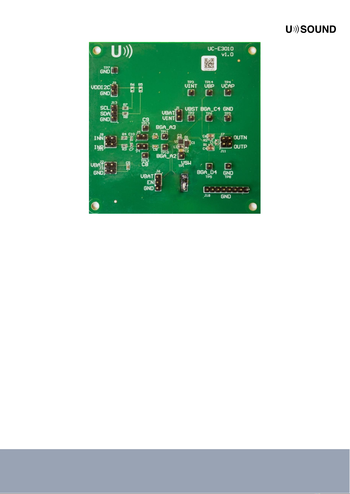
For performing a power consumption measurement at a certain dBSPL with Tarvos evaluation
board 1.0 UC-E3010 and any kind of signal, the following devices are needed:
•Power Supply (i.e. HMC 8043)
•APX measurement system (i.e. 525 or 515)
•1Ωshunt
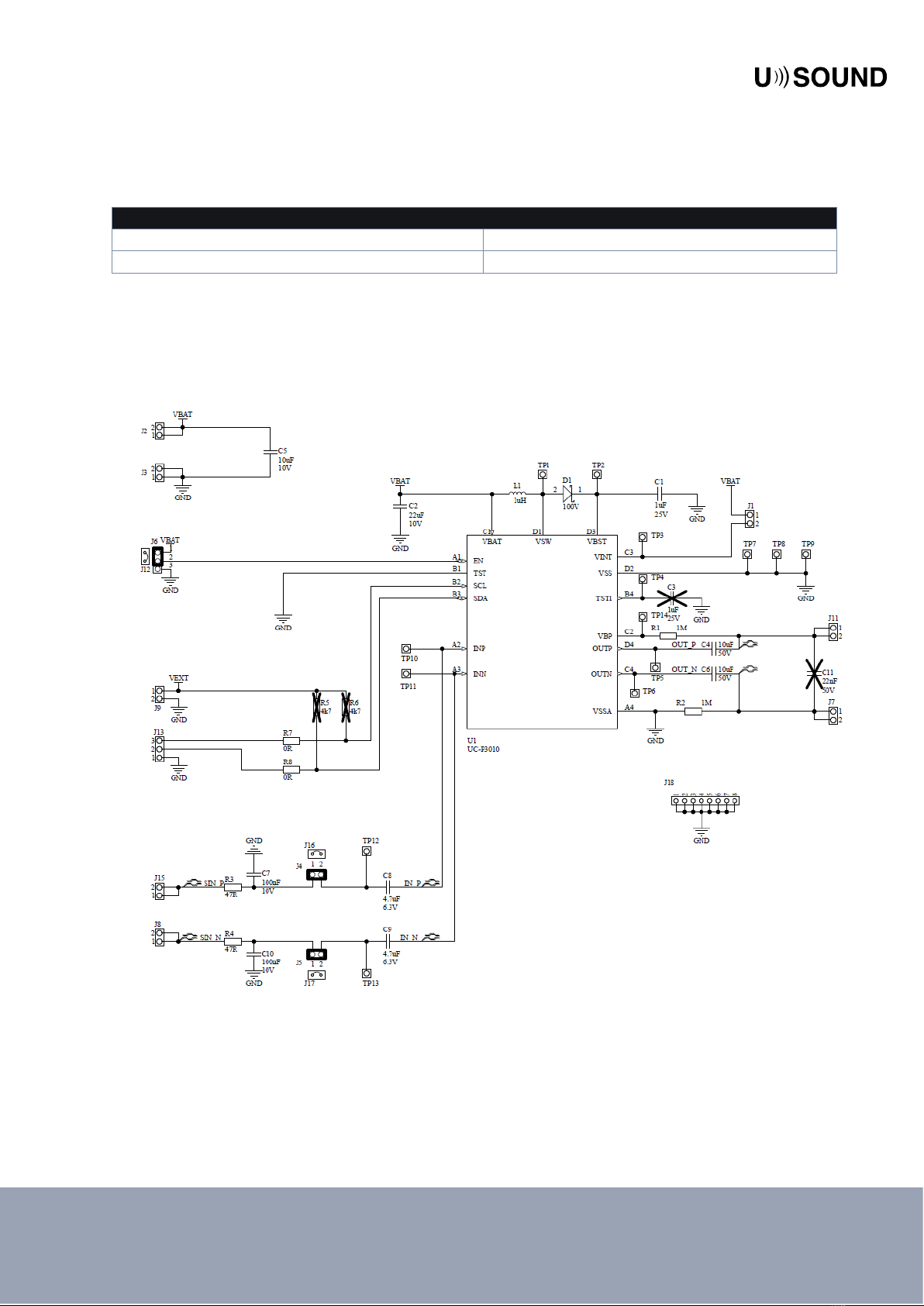
Figure 3 displays how the different elements must be connected.
Figure 3. Power consumption measurement setup with UC-E3010

8
Tarvos evaluation board 1.0 UC-E3010 | User Manual
NDA required | Released in March 2023
SOFTWARE MEASUREMENT SETUP
First, the necessary settings for input and output need to be chosen in the APx measurement software.
These settings can be found in the signal path setup and should be set according to Figure 4. It is
important that the option for the high-pass filter is selected to be “DC”.
Figure 4. Input / Output settings in the APx software
The signal acquisition measurement type is preferred for its higher sampling rate (i.e. 90kHz or even
higher) that can be set (in the Signal Path Setup, or in Advance Settings within Signal Acquisition),
which is convenient for current (voltage on shunt) measurements of non-periodic signals.
The analog output level can be set for obtaining the curve for the Signal Acquisition measurement, as
shown in Figure 5.
Figure 5. Signal Acquisition waveform - current (voltage on shunt)

9
Tarvos evaluation board 1.0 UC-E3010 | User Manual
NDA required | Released in March 2023
It can be observed that the waveform is above 0 always, which indicates a DC component and a proper
polarity in the setup of the balanced signal. In order to obtain a single value result that would
determine the power consumption over time (the arithmetic mean or average value), the arithmetic
mean value can be derived from the right-click menu on the acquired waveform, like in Figure 6.
Figure 6. Derived Result - Arithmetic Mean
The Arithmetic Mean value for the current would then appear in a new window, as it is shown on
Figure 7.
Figure 7. Signal Acquisition - single value result arithmetic mean
In this case the value of 0.904 mV, which equals 0.904 mA due to the 1Ω shunt, would be the final
result of the measurement.

10
Tarvos evaluation board 1.0 UC-E3010 | User Manual
NDA required | Released in March 2023
APPENDIX 2 –BILL OF MATERIAL
Designator
Description
Value
Manufacturer
Manufacturer Number
Fitted
Quantity
R7, R8
0 Ohms Jumper
0.1W, 1/10W Chip
Resistor 0603 (1608
Metric) Moisture
Resistant Thick Film
0R
Yageo
RC0603JR-070RL
Fitted
2
C7, C10
0.1µF ±10% 10V
Ceramic Capacitor
X5R 0402 (1005
Metric)
100nF
Murata
GRM155R61A104KA01D
Fitted
2
L1
1 µH Shielded
Inductor Multilayer 1.7
A 100mOhm Max
0805 (2012 metrisch)
1uH
Murata
LQM21PN1R0MGHL
Fitted
1
R1, R2
1 Mohms ±1%
0.063W, 1/16W Chip
Resistor 0402 (1005
Metric) Moisture
Resistant Thick Film
1M
Yageo
RC0402FR-071ML
Fitted
2
TP1, TP2,
TP3, TP4,
TP5, TP6,
TP7, TP8,
TP9, TP10,
TP11,
TP12,
TP13,
TP14
1 Positions Header,
Breakaway Connector
Through Hole Tin
Molex
0901200121
Fitted
14
C1
1µF ±20% 25V
Ceramic Capacitor
X5R 0402 (1005
Metric)
1uF
Murata
GRM155R61E105MA12D
Fitted
1
J12, J16,
J17
2 (1 x 2) Position
Shunt Connector
Black Open Top, Grip
0.100”(2.54mm) Gold
Würth
Elektronik
609002115121
Fitted
4
J1, J2, J3,
J7, J8, J9,
J11, J15
2 Positions Header,
Breakaway Connector
0.100”(2.54mm)
Through Hole Tin
Molex
0901200122
Fitted
8
J13
3 Positions Header,
Breakaway Connector
0.100”(2.54mm)
Through Hole Tin
Molex
0901200123
Fitted
1
C8, C9
4.7µF ±10% 6.3V
Ceramic Capacitor
X7R 0603 (1608
Metric)
4.7uF
Samsung
CL10B475KQ8NQNC
Fitted
2
C4, C6
10 µF ±10% 50V
Ceramic Capacitor
X5R 0805 (2012
Metric)
10uF
Murata
GRM21BR61H106KE43L
Fitted
2

11
Tarvos evaluation board 1.0 UC-E3010 | User Manual
NDA required | Released in March 2023
Designator
Description
Value
Manufacturer
Manufacturer Number
Fitted
Quantity
C5
10µF ±10% 10V
Ceramic Capacitor
X5R 0603 (1608
Metric)
10uF
Murata
GRM188R61A106KE69D
Fitted
1
C2
22 µF ±20% 10V
Ceramic Capacitor
X5R 0805 (2012
Metric)
22uF
Murata
Electronics
GRM21BR61A226ME51L
Fitted
1
R3, R4
47 Ohms ±1% 0.1W,
1/10W Chip Resistor
0603 (1608 Metric)
Automotive AEC-
Q200 Thick Film
47R
Stackpole
Electronics
Inc
RMCF0603FT47R0
Fitted
2
J4, J5
Connector Header
Through Hole 2
position 0.100”
(2.54mm)
Molex
0901200762
Fitted
2
J6
Connector Header
Through Hole 3
position 0.100”
(2.54mm)
Molex
0901200763
Fitted
1
J18
Connector Header
Through Hole 8
position 0.100”
(2.54mm)
Würth
Elektronik
61300811121
Fitted
1
D1
Diode Schottky 100 V
1A Surface Mount
SOD-123W
100V
Nexperia
USA Inc.
PMEG10010ELRX
Fitted
1
LS1, LS2
Fiducial marker
Fitted
2
U1
Mono, MEMS
speaker driver with
I2C control
Usound
UC-P3010
Fitted
1
R5, R6
4.7 kOhms ±1%
0.1W, 1/10W Chip
Resistor 0603 (1608
Metric) Automotive
AEC-Q200 Thick Film
4k7
Stackpole
Electronics
Inc
RMCF0603FT4K70
Not
Fitted
0
C11
220 pF ±5% 50V
Ceramic Capacitor
C0G, NP0 0603 (1608
Metric)
22nF
Murata
GCM1885C1H221JA16D
Not
Fitted
0
C3
1µF ±20% 25V
Ceramic Capacitor
X5R 0402 (1005
Metric)
1uF
Murata
GRM155R61E105MA12D
Not
Fitted
1

12
Tarvos evaluation board 1.0 UC-E3010 | User Manual
NDA required | Released in March 2023
RELATED DOCUMENTATION
Tarvos 1.0 UC-P3010 Product Brief
Tarvos 1.0 UC-P3010 Preliminary Datasheet
Tarvos 1.0 UC-P3010 Application note
Tarvos 1.0 UC-P3010 Register map
COMPATIBLE PRODUCTS
Product Name
Description
Tarvos evaluation
board 1.0 UC-E3010
Evaluation board for testing key features of the USound ASIC linear
audio amplifier.
Carme kit 6 mm UJ-
E1040C06
A speaker evaluation kit for testing acoustical performance of the
USound MEMS speaker Conamara 6 mm.
Carme kit 5 mm UJ-
E1040C05
A speaker evaluation kit for the testing acoustical performance of the
USound MEMS speaker Conamara 5 mm.
Carme kit Ganymede UJ-
E1040G00
A speaker evaluation kit for testing acoustical performance of the
USound MEMS speaker Adap/Achelous.
Conamara
UA-C0501-2T
MEMS speaker for 2-way speaker solution in wearables and
hearables, tweeter, 5 mm diameter.
Conamara
UA-C0601-2T
MEMS speaker for 2-way speaker solution in wearables and
hearables, tweeter, 6 mm diameter
Conamara
UA-C0601-2F
MEMS speaker for wearables and hearables, full bandwidth, 6 mm
diameter.
Achelous UT-P2020
MEMS speaker for in-ear audio solution, hearables, full-bandwidth,
rectangular
Adap UT-P2023
MEMS speaker for free-field applications, rectangular
IMPORTANT NOTICE AND DISCLAIMER
USound GmbH (“USound”) makes no warranties for the use of USound products, other than those
expressly contained in USound’s applicable General Terms of Sale, located at www.usound.com.
USound assumes no responsibility for any errors which may have crept into this document, reserves
the right to change devices or specifications detailed herein at any time without notice, and does not
make any commitment to update the information contained herein. No license to patents or other
intellectual property rights of USound are granted in connection with the sale of USound products,
neither expressly nor implicitly.
In respect of the intended use of USound products by customer, customer is solely responsible for
observing existing patents and other intellectual property rights of third parties and for obtaining, as
the case may be, the necessary licenses. For more information about USound patents visit
https://www.usound.com/patents/.
Important note: The use of USound products as components in medical devices and/or medical
applications, including but not limited to, safety and life supporting systems, where malfunctions of
such USound products might result in damage to and/or injury or death of persons is expressly
prohibited, as USound products are neither destined nor qualified for use as components in such
medical devices and/or medical applications. The prohibited use of USound products in such medical
devices and/or medical applications is exclusively at the risk of the customer.
Table of contents
Other USOUND Motherboard manuals
Popular Motherboard manuals by other brands

ECS
ECS 945GCT-M user manual

Biostar
Biostar M7VIG Pro-D user guide

Chipcon
Chipcon SmartRF CC2420DBK Quick start instructions

EPC
EPC EPC9041 quick start guide

Linear Technology
Linear Technology DC1084A-A Demo Manual

Intel
Intel BLKD945GNTL - LGA775 1066 800FSB 4DDR2 A/V Lan SATA ATX 10Pack... Technical product specification