USound GmbH | Ananke 3.0 UA-E1030
evaluation board user manual
Released February 2020
www.usound.com | sales@usound.com
7
On the output side, a pair of DAC’s, that are built into the DSP, provide the analog signal to the ampliers.
This is the output routing:
Channel 0: Right channel of analog signal
Channel 1: Left channel of analog signal
In order to route a signal from input to output in the SigmaStudio software, drag a line from the starting point
(source channel) to the desired output channel. You must activate the in/outs by checking the checkboxes next
to the desired in/out number.
DSP SETTINGS AND FUNCTIONS
The ADAU1401A in conjunction with SigmaStudio
allows for different signal manipulations, some of
which shall be explained here by a small project. Use
the talkthrough DSP project and modify it, this way the
lower level hardware settings will be set correctly. Delete
the yellow connections by clicking on them and hitting
del.
Please note: It is possible to zoom the workspace view
of SigmaStudio, however if the zoom factor is not set to
the native/original value it won’t be possible to change
parameters of the building blocks!
To implement a simple low pass lter, that attenuates
the high frequency parts of the signals above 12 kHz,
navigate to the general 2nd order stereo lter by using
the tree toolbox, drag the lter into the workspace and
connect the outputs from the mixer to the input of the
lter. By clicking on the blue window of the lter block,
the lter settings appear. Select LP from the dropdown
menu and type 12000 into the freq. eld.
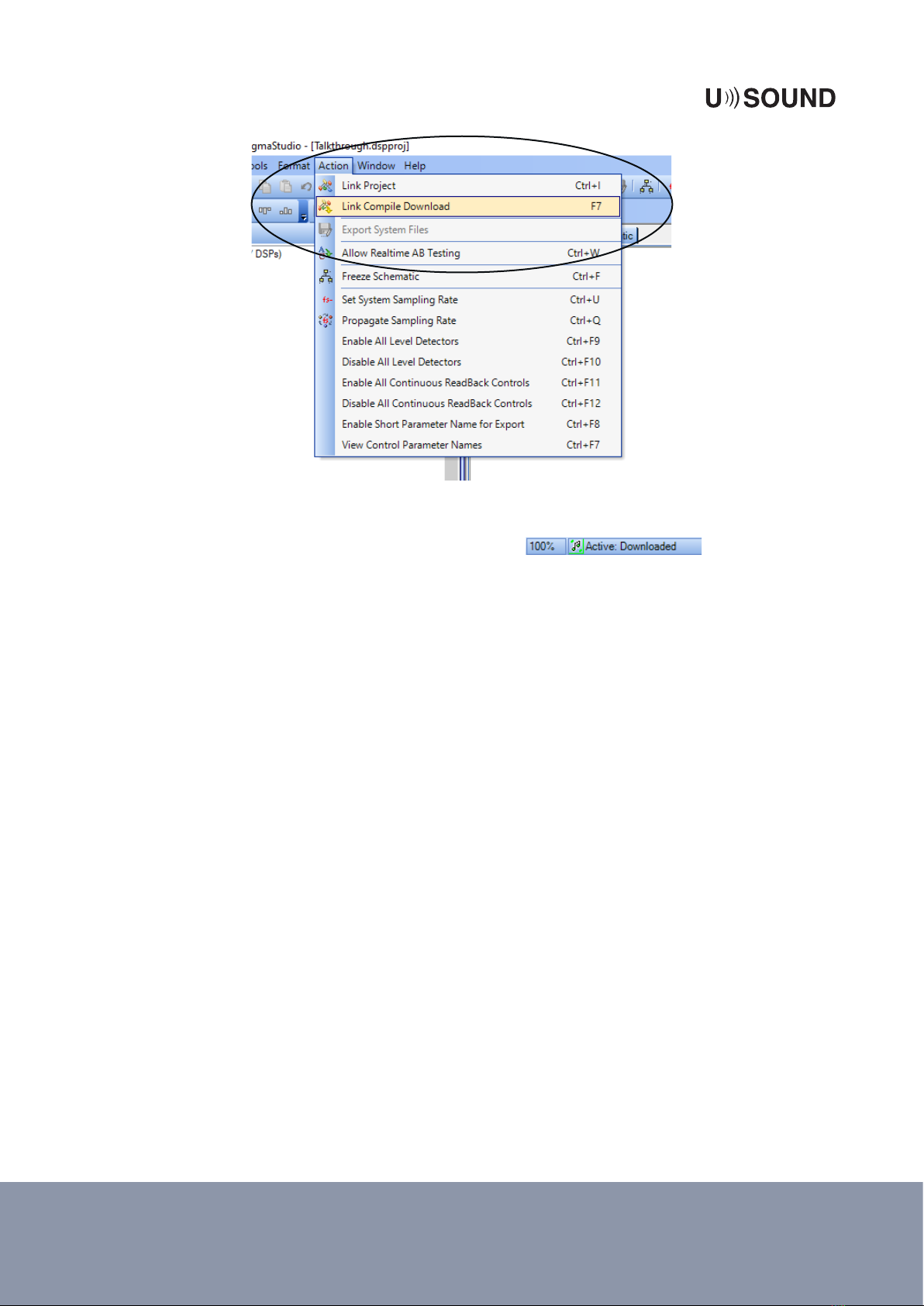
Finalize the project, by connecting the outputs of the
lter to the DACs. The project should now look like the
one in gure 5.
Figure 4: Link Compile Download
A description of most DSP building blocks can be found on the Analog devices website in the SigmaStudio
Toolbox documentation https://wiki.analog.com/resources/tools-software/sigmastudio/toolbox.