VICOR HD Series User manual

UG:118 vicorpower.com Applications Engineering: 800 927.9474 Page 1
Features
nOscilloscope probe jack for output voltage and ripple measurements
nSimple to use
nRing lug connections
Introduction
The Customer Evaluation Board oers a convenient means to evaluate the
performance of Vicor’s high density converter (HDC) Brick module and has been
optimized for user convenience. Please refer to the appropriate HDC datasheet for
performance and operating limits. The datasheets are available for downloading at
vicorpower.com.
Please refer to Figure 1 for locations of the input and output connections as viewed
from the component side. Wires may be soldered directly to the pads instead of ring
lugs if desired to minimize circuit impedances.
NOTE: The Customer Evaluation Board has footprints for both A and B Series HDC modules, but only
one module can be populated on the evaluation board.
HD Series Brick Evaluation Board
USER GUIDE | UG:118
Written by: Michael DeGaetano
Associate Product Line Engineer
July 2014
Contents Page
Features 1
Introduction 1
Set Up 2
Recommended 3
Hardware
Thermals 3
Ordering Info 3
Test Point List 4
Bill of Materials 4

UG:118 vicorpower.com Applications Engineering: 800 927.9474 Page 2
Set Up
The Customer Evaluation Board should be set up as follows:
Note: Care should be taken to avoid reversing polarities if connecting to the opposite
(solder) side of the board.
+IN, –IN
Connect a high-quality, low noise power supply to the +IN and-IN terminals of the
Customer Evaluation Board. The startup slew rate of the input source should be no
greater than 1 V/µs. The interconnect leads should be heavy gauge and as short as
possible. Additional capacitance may have to be added on the evaluation board to
make up for impedances in the interconnect leads as well as deficiencies in the source.
+OUT, –OUT
The load should be connected to +OUT and –OUT terminals of the evaluation board
with short leads of suitable gauge to carry the output current and minimize losses. The
evaluation board can be connected directly to the application for which the module is
intended. However the interconnect impedances between the evaluation board and the
application can greatly aect the transient response. For applications where transient
response is critical, the user should consider mounting the HDC module directly to
the target application PCB. Test points TP14 (+OUT) and TP06 (-OUT) can be used to
monitor the output.
Primary Control (PC)
The PC can be used to disable the HDC or provide a primary referenced bias supply. The
module can be disabled by connecting PC (TP03) to –HDC_IN (TP05).
Trim (TR)
The S01 switch on the Customer Evaluation Board can be used to enable or disable
output voltage trimming on the HDC. Potentiometer R12 can be adjusted to trim the
output voltage of the converter.
Figure 1.
HDC Customer Evaluation Board
layout drawing, component side

UG:118 vicorpower.com Applications Engineering: 800 927.9474 Page 3
GND
The GND terminal of the Customer Evaluation Board is provided for basic conducted EMI
testing of the HDC, during which it should be connected to earth ground.
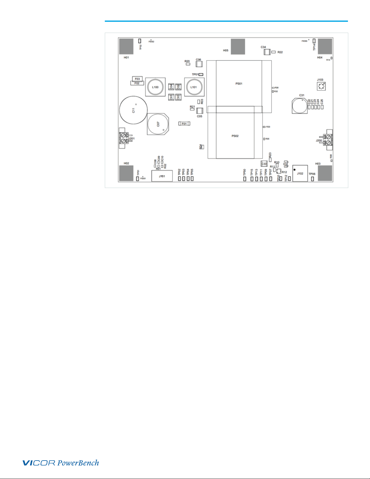
Output Voltage Measurement Jack (J103)
This connector is provided to make accurate measurements of the output voltage of the
HDC. Many types of scope probes may be directly connected to this point if the probe is
equipped with a removable plastic sheath. To avoid creating ground loops when making
measurements of the output or input voltage, these measurements should be made
separately.
Input Current Measurement
A current probe can be passed around the +IN lead connected to the HDC.
Note: The input filter consists of capacitors C01, C02, C03, C04 and common-mode inductors L100 and
L101 on the Customer Evaluation Board. This filter is downstream of input current measurements.
Efficiency Measurement
As the HDC can deliver and consume large currents, the eect of the PCB must be
considered when making an eciency measurement. Be certain to accurately measure
the voltage directly at the HDC using the appropriate pair of contact points located at the
corners of the HDC.
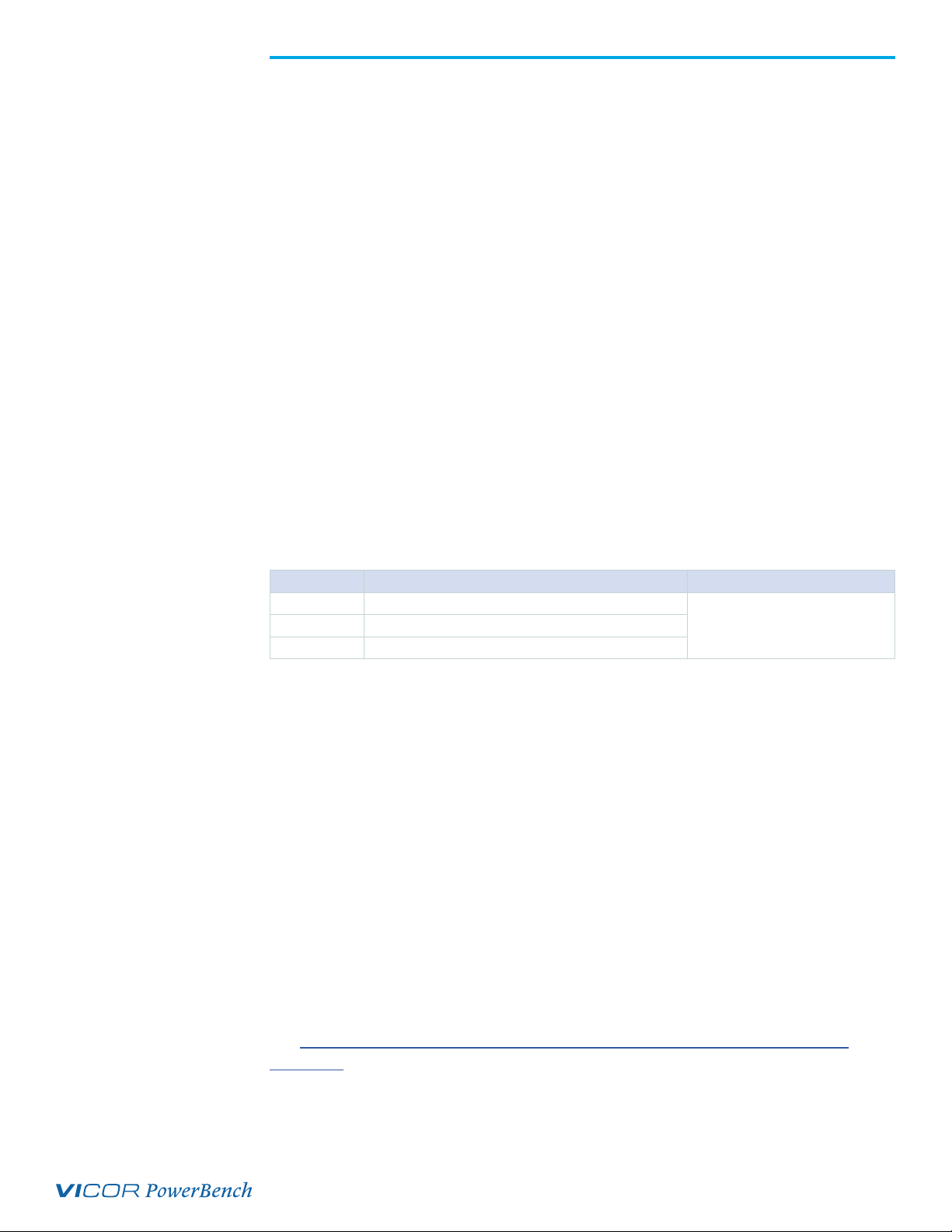
Recommended Hardware:
Qty Description Manufacturer P/N
5 # 10-32 lock washer
Kit # 410625 # 10-32 screw
5 # 10-32 hex nut
Kit # 41062 is included with the Customer Evaluation Board.
Thermals
For most lab environments a fan blowing across the evaluation board is recommended.
For additional thermal information regarding the HDC refer to the datasheet or contact
Vicor Applications Engineering for assistance (800) 927-9474.
NOTE: The HDC Customer Evaluation Board can operate between -20 to 100°C.
Caution
The HDC Customer Evaluation Board can comfortably operate at surface temperatures
which may pose a thermal hazard to the operator. Be careful not to touch any exposed
surface. HDCs may operate at potentially dangerous voltages and pose and energy
hazard. The Customer Evaluation Board is not intended for use in end item equipment.
Ordering Information
The Customer Evaluation Board is specified by replacing the “–00” sux with “–CB” to
the appropriate HDCC model number.
See: http://www.vicorpower.com/dc-dc-converters-board-mount/hd-brick-dc-dc-
converters for model number listings.

UG:118 vicorpower.com Applications Engineering: 800 927.9474 Page 4
Test Point List
Test
Point
Reference
Description Comments
TP01 +HDC_IN +IN of converter after input filter
TP02 FT
TP03 PC
TP05 -HDC_IN -IN of converter after input filter
TP06 -OUT
TP07 SGND
TP09 FB
TP10 TR
TP11 VDDB
TP12 VDD
TP14 +OUT
TP52 +IN
TP51 -IN
Bill of Materials
Ref.
Desc. Description Digi-Key
Manufacturer
Digi-Key
Part #
Future
Manufacturer
Future
Part #
C01
CAP X7T 0.68 µF
10% 450 V 2220 TDK 445-7776-1-ND TDK C5750X7T2W684K-
200KA
C02
C03
C04
C05 CAP X7R 2200 pF
10% 250 V 2220 Murata 490-3480-1-ND Murata GA355QR7GF222K-
W01L
C06
C07 N/A N/A N/A N/A N/A
C11
C21
CAP X7R .22 µF
10% 50 V 1206 AVX 478-1560-1-ND AVX 12065C224KAT2A
C22
C23
C24
C25
C31
CAP ALEL
1000 µF 20% 25V
SMD 13.5 X 13.5
Panasonic PCE3462CT-ND No Stock No Stock
C33 CAP X7R 2200 pF
10% 250 V 2220 Murata 490-3480-1-ND Murata GA355QR7GF222K-
W01L
C34
F01 N/A N/A N/A N/A N/A
F02
FUSE 4 A 425
VDC FAST
3.6 X 11 SMD
No Stock No Stock No Stock No Stock
F03 N/A N/A N/A N/A N/A
Table 1.
Test Point descriptions
Table 2.
Bill of materials

UG:118 vicorpower.com Applications Engineering: 800 927.9474 Page 5
Ref.
Desc. Description Digi-Key
Manufacturer
Digi-Key
Part #
Future
Manufacturer
Future
Part #
J101
CONN 5POS
SINGLE ROW
RIGHT ANGLE
Molex Inc WM1893-ND No Stock No Stock
J102
CONN 10POS
90DEG THRUHOLE
FEMALE 0.100SPC
Sullins S5519-ND Sullins PPTC052LJBN-RC
J200 CON 2 CKT TERM
BLK SMD No Stock No Stock No Stock No Stock
J201
L100 IND COM
MODE 11mH
-25%+45% 5.0 A
.70x.65
No Stock No Stock No Stock No Stock
L101
PS01 Model Specific Vicor Model Specific Vicor Model Specific
PS02
R01 RES 374K OHM
1/8 W 1% 0805 Panasonic P374KCCT-ND Panasonic ERJ-6ENF3743V
R02
R03 RES ZERO OHM
JUMPER 2 A 1206 Vishay 541-0.0ECT-ND Vishay CRCW-
12060000Z0EC
R04 N/A N/A N/A N/A N/A
R05 RES 23.7 OHM
1/8 W 1% 0805 Panasonic P23.7CCT-ND Panasonic ERJ-6ENF23R7V
R08 RES 0 OHM
JUMPER 1 A 0603 Panasonic P0.0GCT-ND Panasonic ERJ-3GEY0R00V
R10 N/A N/A N/A N/A N/A
R11 RES 20 OHM
1/4 W 1% 1206 Panasonic P20.0FCT-ND Panasonic ERJ-8ENF20R0V
R12
RES 100K OHM
1/4 W 20% POT
3636
Murata 490-2645-1-ND Murata PVG3A104C01R00
R20
RES 23.2K OHM
1/4 W 1% 1206 Panasonic P23.2KFCT-ND Panasonic ERJ-8ENF2322V
R21
R22
R23
R30
N/A N/A N/A N/A N/A
R32
R33
R35
R36
S01 SW DIP SPDT
1POS SMD No Stock No Stock No Stock No Stock
Table 2 (Cont.).
Bill of materials

The Power Behind Performance
Rev 1.0 07/14 vicorpower.com Applications Engineering: 800 927.9474 Page 6
Figure 2.
HDC Customer Evaluation
Board Schematic
Table of contents
Other VICOR Motherboard manuals

VICOR
VICOR VI Chip VTM User manual

VICOR
VICOR VI Chip VTM User manual

VICOR
VICOR DCM2322 User manual

VICOR
VICOR ChiP DCM3623 User manual

VICOR
VICOR VI Chip BCM User manual

VICOR
VICOR PI352 series User manual

VICOR
VICOR 4623 User manual

VICOR
VICOR PI3740-00-EVAL1 User manual

VICOR
VICOR VITA62 3U User manual

VICOR
VICOR PI3741-0x-EVAL1 User manual