Utopia Lustre series User manual

Bathroom Installation Instructions

INSTALLATION INSTRUCTIONS
WWW.UTOPIAGROUP.COM
page 2
Contents
Base Units
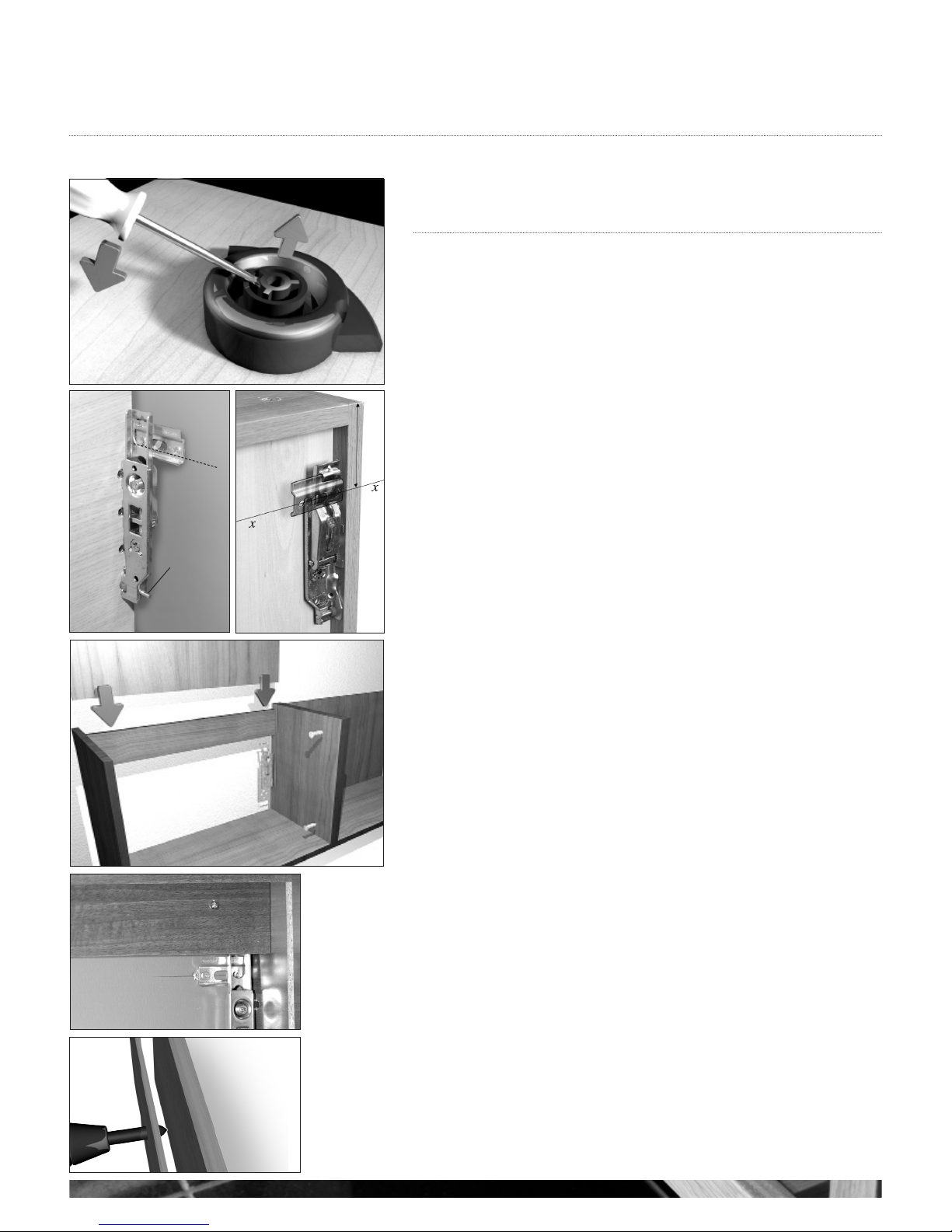
Fitting Base Units 3
Base Units and Drawer Packs 3
Fitting Wall Hung Base and Wall Units 4
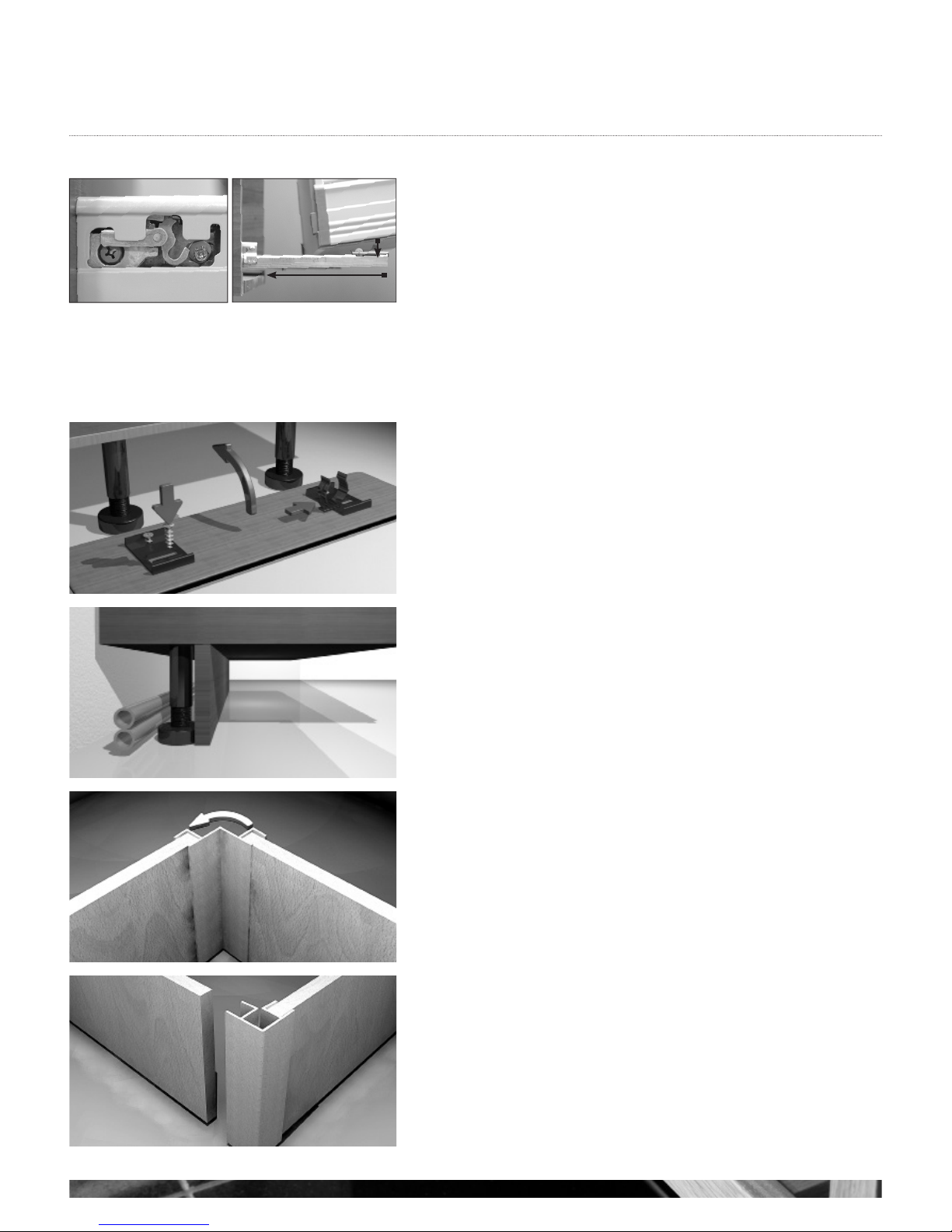
Adjusting a Soft Close Drawer Box 5
Fitting a Plinth 5
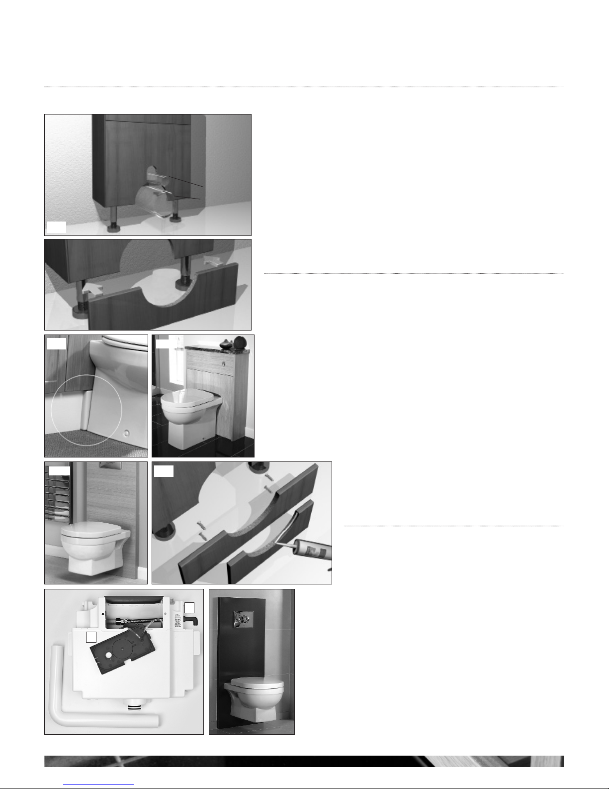
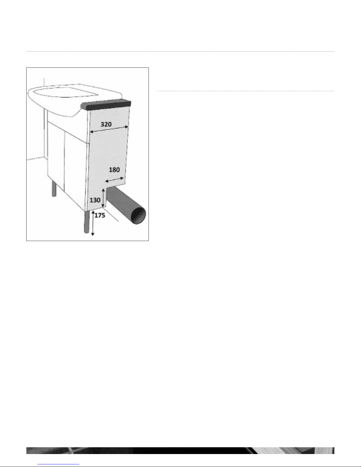
WC Fascia Cut Outs 6
Utopia Push Button Concealed Cisterns 6
Dual Flush Push Button Cistern Features 6
WC Panels 6
Cut-Out Semi Recessed Washbasin Units 7
Wall Units
Fitting Wall Cabinets 8
Fitting the Lighting Unit 8
Access and Removal of Transformers and Front Fascia 8
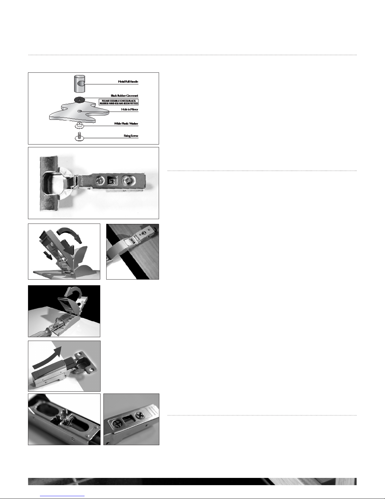
Mirror Cabinet Handle Fitting 9
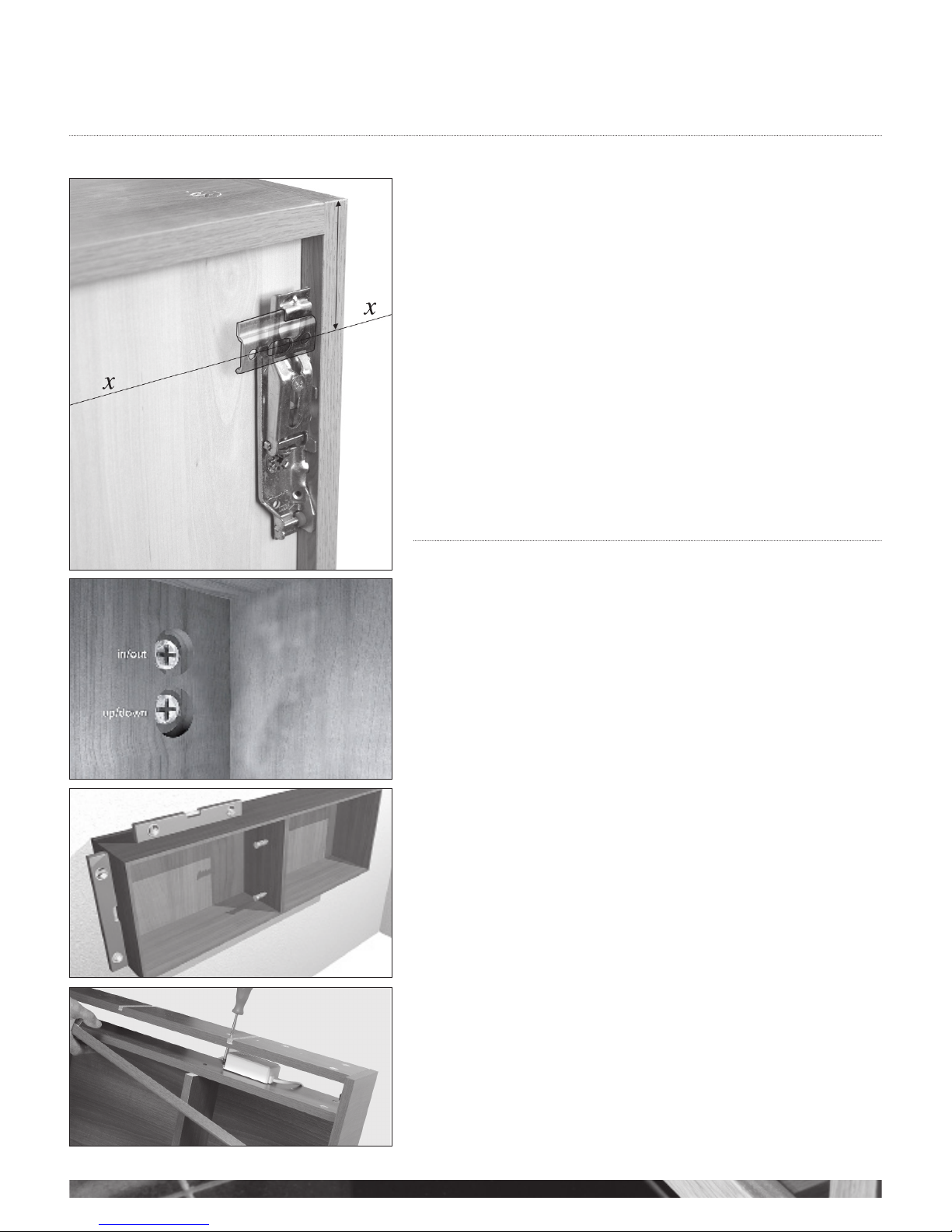
Door Adjustment 9
Fitting a Mirror Door onto a Unit 9
Soft Close Hinge Mechanism, Removal and Re-Fitting 9
Mirrors
Fitting a Mirror 10
Fitting Designer Illuminated, Curved and Modular Offset Mirrors 11
Lighting, Flyover Shelves and Cornice
Fitting Flyover Shelves 12
Fitting LED Downlighters 12
Fitting Chrome Bow Lights 12
Fitting Wall Mounted Mirror Lights 12
Tall Units
Fitting a Tall Glass Shelf Display Unit and
All Other Tall Units 13
Modular Units
Fitting Wall Hung Base and Wall Units 14
Modular Mirror Fitting 15
Modular Sliding Mirror 15
Mirror Cabinet Handle Fitting 16
Door Adjustment 16
Fitting a Mirror Door on to a Unit 16
Soft Close Hinge Mechanism, Removal and Re-fitting 16
Fitting a Square Profile Laminate Worktop 17
Basin Waste Recommendation 17
Adjusting a Soft Close Drawer Box 17
Halo and Qube Furniture
Fitting Hinged Door Mirror Unit 18
Fitting Mirror Drawer Unit 18
Fitting Qube Unit 19
Fitting Halo Twin Base Unit 19
Fitting Side Cabinet 20
Fitting Cloakroom Cabinet 20
i-Line Furniture
Fitting i-Line 50mm Side Panels 21
Fitting i-Line Wall and Mirror Units 22
Symmetry Furniture
Fitting Symmetry Modular Fitted/Freestanding Base Units 23
Fitting Symmetry Worktops / Solid Surface 23
Decorative End Panels 24
Fitting Side Panels with an External Filler Panel 24
Fitting Symmetry Plinths 24
Plinth Lighting 24
Downton
Fitting Traditional Base Unit 25
Downton 26
Bath Panels
Bath Panel Component Identification 27
Bath Panel Installation 27
Definity Fitted Bath 28
Free-standing Bath 29
Fitting Symmetry Baths 30
Fitting Symmetry Bath Side Panels 30
Fitting Symmetry panels with end storage unit 30-32
Geo
Geo Drawer Unit 35
Geo Integra Solid Surface and Freeflow Basin 35
Tap Holes
Drilling For Taps in the Worktop 36
Drilling a Tap Hole In a Gelcast Cloakroom Washbasin 36
50mm Laminate Worktops 36
Solid Surface and Laminate Worktops
Installation of Laminate and Solid Surface Worktops 37
Fitting a Worktop 38
Installing a Washbasin into a Worktop 39
Washbasin Fascia and Worktop Cut Outs 39
Washbasin Waste Recommendation 39
Fitting a Solid Surface Apron Standard
and Short Projection 40
Solid Surface Shelves and Shelf Supports 40
50mm Decorative Floating Shelves
Fitting a 50mm Shelf with an Adjustable Support 41
Roseberry Painted Products
Fitting Instructions 42
Modular 2017 ( Star, Lustre, Opula )
Fitting Instructions 53
Care and Maintenace
Guide 59
Important Note
These fitting instructions refer to fitting Utopia
Furniture to a solid wall. If your bathroom has
studded walls, please use appropriate plasterboard
fixings such as the ones illustrated here, available
from DIY stores throughout the UK.
PLEASE READ THESE INSTRUCTIONS CAREFULLY BEFORE COMMENCING WORK
All units are packed together with a relevant fitting pack and are identified by a label which appears on the front of the box and the rear of the unit.
It is advised that fitting commences from a corner wherever possible, ensuring correct spacing should a corner filler be used.
It is also advised that all doors and fascias are removed prior to fitting to avoid unnecessary damage occurring.
Please note that some of Utopia’s units, sanitaryware and worktops are heavy. Always take care when lifting, and follow health and safety guidelines.

WWW.UTOPIAGROUP.COM
page 3
Base Units
FITTING BASE UNITS AND TALL BASE UNITS
NOTE: SHOULD THE FLOOR BE UNLEVEL AND YOU WISH TO LOWER THE
PLINTH HEIGHT FROM 175mm YOU WILL NEED TO CUT THE LEGS TO THE
REQUIRED HEIGHT (REMOVING UNWANTED MATERIAL FROM THE TOP) BEFORE
FITTING THEM TO THE BASE OF THE UNIT
Attach the plastic legs by pushing them into the sockets on the underside of the unit. It is
advised to give the base of the leg a slight tap with a hammer to ensure a good connection
in the socket (see g 1).
Adjust the leg to approximately the correct height of 175mm (see g 2). Having ensured
all relevant pipework is completed, position the unit on its legs against the wall. Adjust the
legs if necessary to ensure the unit sits level in both directions by using a spirit level on all
sides (see g 3).
Maintain the plinth height of 175mm as near to the optimum as possible.
Once the unit has been positioned level, remove the back (if applicable) and fix the unit
to the wall via the back rail or stretcher plates (see g 4). If you are attaching this unit to a
plasterboard wall please ensure that you use the correct fixings.
Once all units are in place they can be joined together by means of drilling and screwing
through adjacent side panels. We suggest making fixing less obvious by drilling behind
hinges or loose shelves (see g 5). Once all the units are securely fixed, ensure that all
the back panels that were removed earlier are slid back into position before proceeding
further.
Please note that many back panels are double-sided and have a different finish on either side.
Always check that you slide the panel in with the correct finish facing forwards before the
worktops are fitted (see g 5).
Please Note
When fitting a base unit for a Short Projection Solid Surface basin, the back rail has a gap to
allow the inset basin to fit nearer the wall. Fix this unit to the wall through the side cheeks
of the back rail, A & B. This will also assist in supporting the worktop (see g 6).
BASE UNITS AND DRAWER PACKS
This unit should be fitted the same way as a normal base unit. Please note drawer packs
do not have 8mm slide-in backs, this allows easy access to the top rail for fitting purposes.
If your unit is to be wall hung, please refer to the section ‘fitting a wall hung base unit’
on page 4.
Important
Check all products before fitting.
Do not fit any defective products, contact your supplier immediately.
Utopia Bathroom Group assumes that this/these product/s will be fitted by an experienced
and competent installer. Failure to do so will result in the invalidation of Utopia’s guarantee.
Under our policy of improvement we reserve the right to alter materials or specification
in line with our continuing programme of product and service development.
g 4
g 3
g 2
g 1
g 5
A
B
g 6

INSTALLATION INSTRUCTIONS
WWW.UTOPIAGROUP.COM
page 4
Base Units
g 1
FITTING WALL HUNG BASE UNITS AND WALL UNITS
Units should be fitted by professional installers.
All base units whether with legs or wall-hung come complete with leg sockets fitted for
transit purposes. If the units are to be installed wall-hung, please remove these sockets
prior to fixing. To do this, insert a small flat headed screwdriver into the centre section and
carefully lever out the centre pin. The bracket can now be easily removed (see g 1).
It is advised that a line is now drawn along the length of the wall, level with where the units
are to be fitted at the desired height above floor level. If the space between the floor and
the unit is to be 175mm then the line shown as x(see g 2) should be drawn to suit the
unit being fitted.
Wall hanging brackets need to be fixed to the carcass when they are sold separately. The
brackets should be fixed the correct way up by knocking four prongs into the holes at the
rear of the carcass. Ensure that the securing pin is knocked into place, (see g 3).
Fix the brackets to the wall with appropriate plugs and screws for your wall type (not
supplied).
The units then simply hook onto the wall fixed brackets. Adjustment to gain a level surface
is as follows,
A - Adjust this to pull the cabinet into the wall
B - Adjust this to move the cabinets up or down (see g 3);
Pull the cabinets tightly in against the wall using the adjustment screws on brackets. It is
important to ensure you have sufficient support for the weight of pottery and unit plus
contents when fitting wall hung units.
Once all units are in place they can be joined together by means of drilling and screwing
through adjacent side panels. We suggest making fixing less obvious by drilling behind
hinges and/or loose shelves, (see g 4).
A securing screw should then be fitted through the back of the unit, through the fixed back
rail of the cabinet and into the wall on a base unit, this will help to stabilise the unit
(see g 5 point 4).
Now that all the units are securely fixed, ensure that all the back panels that were removed
earlier are slid back into position before proceeding further. Please note that many back
panels are double-sided and therefore have a different finish on either side. Always check
that you slide the panel in with the correct finish facing forwards, (see g 4).
For all units with a fixed back panel we advise that you drill a 10mm hole through the back
panel and then fit a stabilising screw though the back rail of the cabinet into the wall. The
10mm hole can be covered with one of the caps supplied or if positioned appropriately, by
the loose shelf of the unit, when applicable (see g 6).
g 4
g 3
TOP OF UNIT
Back Panel Back Rail
10mm drill
Wall
6 in/out
4
g 5
g 6
level line
securing pin
A
in +
out
up +
down B
g 2

WWW.UTOPIAGROUP.COM
page 5
Base Units
ADJUSTING A SOFT CLOSE DRAWER BOX
Drawer boxes are factory installed and should not need to be adjusted. However, if
adjustment is required, pull the drawer box out and remove the Utopia branded plastic
cover cap. This will reveal the two adjustment screws. Use one of the screws to raise and
lower the drawer box (see g 1 A) and the other (see g 1 B) to move it, left and right.
Large drawer units have a fixing bracket, located in the centre of the drawer box on the
underside, that needs to be slackened off before adjustment and re-tightened after.
If you need to remove a drawer box, lift up and away from the drawer runners.
To replace the drawer box, fully extend the drawer runners, place the drawer box onto
them and close the drawer. The box will clip itself in to place upon closing (see g 2).
To remove drawer front from the side turn screw (see g 1 C).
A
B
g 2g 1
FITTING A PLINTH
Cut the plinth to the required length. If you are using a Plinth Return to go around a 90°
corner, reduce the overall length by 20mm to accommodate the corner piece.
On the reverse of the plinth mark the position of the cabinet legs in order to fix the leg
plates and cups. Fix with number 6 x 5/8 screws.
Push the plinth complete with clips onto the legs (see g 3).
Alternatively;
As another option to wall hanging or fitting the plinth on the front legs of the cabinet, you
can remove the front legs and the plinth may be fitted to the rear legs only, (see g 4).
Please Note
Before fitting always check that you have identified the correct finish side of the plinth.
Plinth Returns can be used to take a plinth round an internal (see g 4) or an external (see
g 5) corner.
g 3
g 5
g 6
g 4
Plinth can be fitted to the rear legs
C

INSTALLATION INSTRUCTIONS
WWW.UTOPIAGROUP.COM
page 6
Base Units
WC FASCIA CUT OUTS
When fitting a WC it may be necessary to cut the bottom fascia to accommodate both the
soil pipe and flush pipe. Use the pottery as a template (see g 1, 4 and 5).
NOTE: Wall-hung WC pottery should not be screwed directly to the fascias as the WC
units are not load carrying.
Wall-hung pottery needs a steel supporting frame which has two large bolts that need to
be accommodated within the fascia panel. The plinth must also be cut to accommodate
the soil pipe (see g 2) if applicable.
You may have to remove one of the rear legs of this unit to accommodate the waste pipe.
For aesthetic looks a pan return should be used to act as a filler between the front of the
plinth (if applicable) and the back of the WC pan (see g 3). To ensure a good fit, screw
through the back of the plinth into the pan return (see g 6).
Re-seal all cut edges.
g 2
g 3
g 6
g 1
Flush Pipe
Waste Pipe
g 4
g 5
UTOPIA PUSH BUTTON CONCEALED CISTERNS
The concealed cistern for use in Utopia Furniture is pneumatically operated by a small push
button which is both aesthetically pleasing and functional.
The cistern unit complies with the new regulations, maximum 6 litres flush volume, and is
totally installer and user friendly.
DUAL FLUSH PUSH BUTTON CISTERN FEATURES
1. 190 x 100mm clip-off service panel.
2. Complete with push-fit water inlet pipe and internal isolation valve (see g 7).
1
2
g 7
WC PANELS
These panels are held in place by your wall-hung or back-to-wall
toilet pan.
Additional fixings can be hidden behind the push button plate if
required (see g 8).
g 8

WWW.UTOPIAGROUP.COM
page 7
Base Unit Cut-Outs
g 1 CUT-OUT SEMI RECESSED WASHBASIN UNITS
The cut-out washbasin unit incorporates a void at the back to allow pipework
to pass behind the unit. (see g 1).

Wall Units
INSTALLATION INSTRUCTIONS
WWW.UTOPIAGROUP.COM
page 8
FITTING WALL CABINETS, DELUXE MIRROR UNITS,
DOUBLE FULL MIRROR UNITS, WALL CABINETS, OPEN
SHELF UNITS AND QUBE MIRROR CABINET
Wall cabinet hanging brackets are supplied with the unit.
It is advised that a line is drawn along the length of the wall, level with where the units are
to be fitted at the desired height above floor level. If tall units or tall sit on units are to be
used, these will determine the height of line x, i.e. the top of the unit being 1955mm if a
175mm plinth is to be used (see g 1).
If you are attaching this unit to a plasterboard wall please ensure that you use the correct
fixings.
The units then simply hook onto the wall fixed brackets. Adjust to gain a level top edge
using the adjustment screws - (see g 2). Also see instructions on page 4 (g 2. and 3).
A securing screw should be placed at the back of the unit to stabilise it. The screw should
be located through the fixed back rail at the back of the cabinet (see g 6 point A).
Once the units are in place they can be joined together (see g 3).
Once the unit has been levelled and pulled against the wall, fix conceal cover over
adjustment hole in back of unit with 10mm.
Cover caps supplied.
To fit mirror doors please refer to the section on fitting a mirror door on page 9.
FITTING THE LIGHTING UNIT
These units come with a transformer pre-installed that will power one extra light to the two
supplied with the unit, and the shaver socket.
If more than three lights are required, additional transformers must be added. These will fit
next to the existing transformer at the top of the unit, provided that the top of the unit is cut to
accommodate the transformer. Should the transformer be fitted with a 13 amp plug this must
be removed.
ACCESS AND REMOVAL OF TRANSFORMERS AND FRONT FASCIA
Carefully remove the fascia from the front of the unit and access the transformer
(see g 4).
Cabinet interior
g 1
g 3
TOP OF UNIT
g 4
g 2

WWW.UTOPIAGROUP.COM
page 9
Wall Units
MIRROR CABINET HANDLE FITTING
Please ensure all components are fitted in accordance with the diagram (see g 1).
Please fit hand tight only using a manual screwdriver. Do not overtighten as this may cause
damage to the mirror door.
DOOR ADJUSTMENT
When adjustment is necessary to the doors, follow these directions (see g 2):
W - Lift this clip to release the door from the carcass
X - Adjusts the door’s horizontal position
Y - Adjusts the door’s vertical position
Z - Adjusts the door’s vertical position or this screw being in the hinge fixing plate.
FITTING A MIRROR DOOR ON TO A UNIT
Remove the hinges from the units by lifting the tab underneath the hinge indicated by
position W (see g 2).
Place the hinges on to the glass doors by locating them in to their housing (see g 3 B) and
rotating them forward until they lock in to place.
We advise that the hinge plates fitted are loosened off to allow easy fitting of the door.
Align the door back up to the unit and clip the hinges back in to place on the unit (see g
4).
On full mirror units please ensure when fitting the mirror there is no misalignment with the
three mirror hinges to reduce the risk of stress upon the hinge and glass.
Once the door is in the correct position re-tighten the hinge plates to the cabinets and
carry out final adjustment (see g 2).
To remove the hinge from a glass door (see g 5).
a. Insert a small flat headed screwdriver underneath the release catch
situated inside the hinge.
b. Rotate the blade of the screwdriver through 90º.
c. Close the hinge, releasing it from the bracket.
It is vitally important that all doors are adjusted correctly, as over a period of time the
stresses caused by misalignment can result in failure of the bond between the hinge
plate and the glass surface, and your guarantee will become invalid.
SOFT CLOSE HINGE MECHANISM, REMOVAL AND RE-FITTING
1. This is supplied ready fitted to one of the hinges on the unit. Remove this to gain access
to the hinge adjustment screws by sliding the soft close mechanism off the hinge, towards
the door, as shown in diagram (see g 6).
2. To re-fit the mechanism, simply locate the metal tab (see g 7 b) and the two hooks
(see g 7 c) inside the small hole on the hinge (see g 8 d) and push forward and
down until it clicks in to place.
Y
Z
X
W
c
door
g 1
g 2
g 4
g 5
g 8
g 3
B
XY
c
bd
ZW
g 6
g 7

INSTALLATION INSTRUCTIONS
WWW.UTOPIAGROUP.COM
page 10
Mirrors
FITTING A MIRROR
Decide which way you wish to hang the mirror, horizontal or vertical.
Insert the white plastic pegs into the carcass holes (see g 1), ensuring they are pushed
in properly, and straight. (Please note that once the white plastic inserts are fitted into the
holes on the carcass backboard, they cannot be removed).
Drill holes into the wall at the appropriate positions, depending upon which way you are
hanging the mirror. Make sure they are level (using a spirit level).
If you are fitting this unit to a plasterboard wall, please ensure the correct fixings are used.
Hang the mirror onto the screws.
To p
g 1

WWW.UTOPIAGROUP.COM
page 11
Designer Illuminated, Curved and Modular Offset Mirrors
Decide on the position that you want your mirror and mark a horizontal line on the wall.
(see g 1).
Mark out the position of the supporting brackets. It is important that they are fitted as
accurately as possible, so the mirror does not move left or right when installed.
Fix the brackets to the wall using appropriate fixings for your wall type.
Please note that LED lights (when supplied), should be installed by a qualified electrician.
Screw the supplied hanging plates to the rear of the mirror in the position to suit your
desired orientation (see g 2 and 3)
Hang the mirror unit in place on to the brackets.
Please note
When fitting one of these mirrors the installer must allow a minimum distance of 150mm
from the sensor to the next facing surface.
g 1
g 2
g 3
Hanging Plates
Transformer recess
Pockets labelled A for horizontal hanging
Pockets labelled B for vertical hanging
AA
A
B
B
B

INSTALLATION INSTRUCTIONS
WWW.UTOPIAGROUP.COM
page 12
Lighting, Flyover Shelves and Cornice
We strongly recommend that a qualified electrician be used for the installation of
electrical products.
FITTING FLYOVER SHELVES
Three types of material may be used as flyover shelving;
(a) 16mm carcass material
(b) 28mm worktop material
(c) Solid Surface worktop material
All are fitted in the same way, by either;
Drilling through the flyover into the top of the unit (see g 1 example 1)
or
Drilling through the top panel of the carcass and screwing into the flyover
(see g 1 example 2)
Do not screw directly into Solid Surface. There must be a 5mm drill hole to clear the 3mm
surface, then screw into the board only.
FITTING LED DOWNLIGHTERS
Drill a hole in the desired position using a 57mm hole saw and push the light into place.
(see g 2)
Please note that the LED downlighters must be used in conjunction with a transformer.
FITTING CORNICE
We recommend that cornice is fitted to the top of wall units in line with the front of the
cabinet.
or
example 2
example 1
g 2
g 1

WWW.UTOPIAGROUP.COM
page 13
Tall Units
Fixing Spacers
Back rail
Back panel
5mm drill
10mm drill
g 2
g 3
g 4
FITTING A TALL GLASS SHELF DISPLAY UNIT AND
ALL OTHER TALL UNITS
With either drawers or cabinet.
Drill the fixing holes in the back of the unit as follows:
aIn the top and bottom sections of the unit, mark the positions of the two
fixing holes as shown (see gs 1 and 2).
bIn the bottom section of the unit mark the positions of the two holes (see g 2).
Also note drilling method (see gs 3 and 4).
cOnce the hole positions have been marked, open up the hole in
the 8mm back to10mm, to accommodate the cover cap. (see g 4).
Once the unit has been positioned level (using a spirit level on all sides), push the supplied
fixing screws through the Ø5mm holes until they touch the wall. Gently tap the screw
heads to enable the screw points to mark the fixing points on the wall.
Remove the unit from its position and drill the wall in the positions you have just marked. If
you are attaching the unit to a plasterboard wall, please ensure you use the correct fixings
(not supplied).
Replace the unit into the desired position and use the screws provided to fix it to the wall
through the back panel, through the plastic spacers, and into the wall. Ensure the unit is still
level in all directions. Insert the10mm screw covers.
If you are fitting the drawer pack version of this unit, there will not be an 8mm back
behind the drawer boxes, simply fix through the back rail which can be easily accessed by
removing the drawers. See drawer pack information on page 5.
Once all units are in place they can be joined together (if applicable) by means of drilling
and screwing through adjacent side panels. We suggest making fixing less obvious by drilling
behind hinges and shelves.
g 1

INSTALLATION INSTRUCTIONS
WWW.UTOPIAGROUP.COM
page 14
Modular Units
The recommended height from the floor to the top of the basin shown above as Y, is 900mm
FITTING WALL-HUNG BASE UNITS AND WALL UNITS
Wall hanging brackets need to be fixed to the carcass if supplied separately. The brackets
should be fixed the correct way up by knocking four prongs into the holes at the rear of
the carcass. Ensure that the securing pin is knocked into place, (see g 1).
Draw a line along the length of the wall, level with where the units are to be fitted at the
desired height x(see g 2).
Fix the brackets to the wall with appropriate plugs and screws for your wall type (not
supplied).
The units then simply hook onto the wall fixed brackets. Adjustment to gain a level surface
is as follows,
A - Adjust this to pull the cabinet into the wall
B - Adjust this to move the cabinets up or down (see g 1);
Pull the cabinets tightly in against the wall using the adjustment screws on brackets. It is
important to ensure you have sufficient support for the weight of pottery and unit plus
contents when fitting wall hung units.
Once all units are in place they can be joined together by means of drilling and screwing
through adjacent side panels. We suggest making fixing less obvious by drilling behind
hinges and/or loose shelves, (see g 3).
A securing screw should then be fitted through the back of the unit, through the fixed back
rail of the cabinet (where available) and into the wall, this will help to stabilise the unit,
(see g 3).
Now that all the units are securely fixed, ensure that all the back panels that were removed
earlier are slid back into position before proceeding further, (see g 3). Please note that
many back panels are double-sided and therefore have a different finish on either side.
Always check that you slide the panel in with the correct finish facing forwards.
For all units with a fixed back panel we advise that you drill a 10mm hole through the back
panel and then fit a stabilising screw though the back rail of the cabinet into the wall. The
10mm hole can be covered with one of the caps supplied or if positioned appropriately, by
the loose shelf of the unit, when applicable (see g 4).
Handles for wall units are to be fitted by the installer on location according to the
customers requirements.
Units should be fitted by professional installers.
g 3
g 2
level line
securing pin
removeable
back panel
back rail
A
in +
out
up +
down B
TOP OF UNIT
g 1
Back Panel Back Rail
10mm drill
Wall
g 4

INSTALLATION INSTRUCTIONS
WWW.UTOPIAGROUP.COM
page 15
Modular Units
All wall mounted units and basins are supplied as standard with hanging brackets. Please note it is the installer’s responsibility
to obtain fixings that are suitable for the unit to be installed against either a solid or a studded wall; see page 4.
MODULAR WALL MIRROR FITTING
Determine the orientation of the mirror required for this installation, either vertical or
horizontal (see g 1).
It is advised that a line is now drawn along the length of the wall, level with where the unit
is to be fitted at the desired height above floor level at position x(see g 2 and 3).
Fix the brackets to the wall with appropriate plugs and screws for your wall type (not
supplied). (Please see either g 2 or g 3 depending on which brackets you have been
supplied)
Position mirror against the wall slightly above the brackets, then lower until the brackets on
the back of the mirror interlock with those on the wall - (see g 3).
MODULAR SLIDING MIRROR FITTING
Wall cabinet hanging brackets are supplied with the unit.
It is advised that a line is now drawn along the length of the wall, level with where the unit
is to be fitted at the desired height above floor level at position x (see g 4).
If you are attaching this unit to a plasterboard wall please ensure that you use the correct
fixings.
The units then simply hook onto the wall fixed brackets. Adjust to gain a level top edge
using the adjustment screws - (see g 5).
Pull the cabinets tightly against the wall using the adjustment screws on the brackets.
(see g 5).
This unit is 1200mm or 1600mm wide and will need a screw fitted as shown in (see g 6).
A pocket hole has been drilled to the left and right of the top, and can be used when
drilling into the wall for fixing.
Fitting the mirror (packed separately)
Place bottom groove over the two pegs set in the base shelf. (see g 7) top of page 18
Hold the mirror and push the two roller guides into the mirror backboard. (see g 8, page
18).
To remove the mirror release the top roller guides by gently releasing the catch with a
screwdriver, (see g 9). Carefully lift the mirror off the grooves, (see g 7, page 18).
g 1
g 3
g 2
WALL
WALL
MIRROR MIRROR
X
X
X
X
securing pin
A
in +
out
up +
down B
g 4 g 5 g 6
Hanging Plates

WWW.UTOPIAGROUP.COM
page 16
Modular Unit Mirror Door Handles and Door Hinge Adjustment
MIRROR CABINET HANDLE FITTING
Please ensure all components are fitted in accordance with the diagram (see g 1).
Please fit hand tight only using a manual screwdriver. Do not overtighten as this may cause
damage to the mirror door.
DOOR ADJUSTMENT
When adjustment is necessary to the doors, follow these directions (see g 2):
W - Lift this clip to release the door from the carcass
X - Adjusts the door’s horizontal position
Y - Adjusts the door’s vertical position
Z - Adjusts the in/out position of the door.
FITTING A MIRROR DOOR ON TO A UNIT
Remove the hinges from the units by lifting the tab underneath the hinge indicated by
position W in the diagram (see g 2).
Place the hinges on to the glass doors by locating them in to their housing (g 3 B) and
rotating them forward until they lock in to place.
We advise that the hinge plates fitted are loosened off to allow easy fitting of the door.
Offer the door back up to the unit and clip the hinges back in to place on the unit.
On full mirror units please ensure when fitting the mirror there is no misalignment with the
three mirror hinges to reduce the risk of stress upon the hinge and glass.
Once the door is in the correct position re-tighten the hinge plates to the cabinets and
carry out final adjustment (see door adjustment and g 2).
Removing the hinge from glass door - (see g 5).
a. Insert a small flat headed screwdriver underneath the release catch
situated inside the hinge.
b. Rotate the blade of the screwdriver through 90º.
c. Close the hinge, thus releasing it from the bracket.
It is vitally important that all doors are adjusted correctly, as over a period of time the
stresses caused by misalignment can result in failure of the bond between the hinge
plate and the glass surface, and your guarantee will become invalid.
SOFT CLOSE HINGE MECHANISM, REMOVAL AND RE-FITTING
1. This is supplied ready fitted to one of the hinges on the unit. Remove this to gain access
to the hinge adjustment screws by sliding the soft close mechanism off the hinge,
towards the door, as shown in the diagram (see g 6).
2. To re-fit the mechanism, simply locate the metal tab (see g 7 b) and the two hooks
(see g 7 c) inside the small hole on the hinge (see g 8 d) and push forward and
down until it clicks in to place.
Y
Z
X
W
c
door
g 1
g 2
g 4
g 5
g 8
g 3
B
XY
c
bd
ZW
g 6
g 7
g 7 g 8 g 9

WWW.UTOPIAGROUP.COM
page 17
Modular Units
FITTING THE MODULAR SQUARE PROFILE LAMINATE
WORKTOPS - 1006MM, 1206MM, 1606MM LENGTH
Note: Utopia as standard provides 2 brackets with each 1006mm, 1206mm and 1606mm
worktop purchased separately to cover any possible installation. Dependent upon
installation arrangement and number of worktops used, you may find that some brackets
are not required.
If you are installing a fascia box and/or drawer unit along with the worktop(s) (see g 1) and
refer to page 14 of these instructions.
50MM LAMINATE WORKTOPS
Use the Nylon Sleeve Insert, specially designed for use with 50mm laminate worktops,
when fitting a worktop mounted tap.
Drill a small pilot hole at the centre of tap position.
Drill part way from under side a hole of 52-54mm Diameter (see g 3). Then drill a
35mm hole from the top which will accommodate your tap. Insert the nylon sleeve. Use a
quality silicon seal around both hole cuts and insert sleeve and fit tap.
INSTALLATION OF A WORKTOP ON ITS OWN OR
AS THE LOWER WORKTOP OPTION SEEN IN FIG. 1
Work out the desired height on the wall of the shelf location and mark out where the
brackets are going to be. We advise that the brackets are set approximately 300mm in from
the ends of the shelf (see g 2).
Making sure the brackets will be level, screw the brackets to the wall using suitable fixings.
BASIN WASTE RECOMMENDATION
A standard 32mm P trap or bottle trap can be accommodated in all washbasin unit
installations. An in-line trap, or an extendable waste connector can be accommodated in all
washbasins.
ADJUSTING A SOFT CLOSE DRAWER BOX
Drawer boxes are factory installed and should not need to be adjusted. However, if
adjustment is required, pull the drawer box out and remove the Utopia branded plastic
cap. This will reveal the two adjustment screws. Use one of the screws to raise and lower
the drawer box (see g 4 A) and the other (see g 4 B) to move it left and right.
Large drawer units have a fixing bracket, located in the centre of the drawer box on the
underside, that needs to be slackened off before adjustment and re-tightened after.
If you need to remove a drawer box, lift up and away from the drawer runners.
To replace the drawer box, fully extend the drawer runners, place the drawer box onto
them and close the drawer. The box will clip itself in to place upon closing (see g 5).
To remove drawer front from the side turn screw (see g 4 C).
g 1
g 2
g 3
35mm hole
tap
52-54mm hole
Nylon sleeve
A
C
B
g 4
g 5

WWW.UTOPIAGROUP.COM
page 18
Halo Units
1200 HINGED DOOR MIRROR UNIT
Mirror door can be either left hand or right hand.
Fitting the cabinet to the wall,
Remove the door from the unit, care needs to be taken due to the weight of the mirror
door panel
Note: the door hinges are fitted the reverse way to a normal hinged door (see g 2) - the
hinge back plate is fitted to the door not the unit side panel, to release the hinge and door
depress the button at the rear of the hinge body (see fig 2), to remove the door take the
weight of the door and release the hinges working from the bottom up. To re-fit start with
clipping the top hinge first.
Fit cabinet to the wall using the standard cabinet hangers which are pre-fitted to the unit
(see g 4), also see page 14 for full instructions on how to fit the wall bracket and how to
mount and adjust the cabinet.
1200 MIRROR DRAWER UNIT
Fitting this unit requires the front mirror panel to be removed from the unit, care needs to
be taken due to the weight of the mirror panel.
Remove the front mirror panel from the top and bottom drawers boxes (Note the middle
drawer stays with the front mirror panel).
Start with the bottom drawer box (g 2), Insert a cross bladed screwdriver into the catch
release mechanism on the drawer box side and turn clockwise (g 3), ensure that when
you remove the screwdriver from the catch that it remains in the open position, this may
require the front mirror door panel being pulled away from the drawer box slightly, until
the top drawer box has been released.
Once all the drawer boxes sides have been released, pull the mirror panel away from the
cabinet.
Fit cabinet to the wall using the standard cabinet hangers which are pre-fitted to the unit
(see g 4), also see page 14 for full instructions on how to fit the wall bracket and how to
mount and adjust the cabinet.
Once the cabinet has been fitted to the wall securely and adjusted, push the mirror panel
back into the drawer boxes, ensuring that the lock mechanism on each drawer box has
been fully engaged and are in the closed position,
You should hear an audible click as the catches engage, carefully pull open the mirror panel
to ensure all catches have fully engaged before passing off.
For drawer box adjustment refer to page 5 and 18.
g 1
g 1 g 2
g 2
g 3
g 4
g 3
Cabinet
Depress button to release
hinge from backplate
This drawer
box stays
with the
front mirror
panel when
removed.
Top and
bottom
drawer boxes
stay in the unit
Cabinet
INSTALLATION INSTRUCTIONS

WWW.UTOPIAGROUP.COM
page 19
TWIN BASE UNIT 650MM - 1200MM
Draw a line along the length of the wall for the wall brackets (g 2), the line is approx. 30mm
below worktop height, ensure that the line is drawn level.
Measure between the gables ‘Y’ in (see g 2) so that the wall brackets are fitted just to the inside
of the gable
Fix the brackets to the wall by aligning the centre of the top holes in the bracket to the line X
(see g 2), fix bracket with appropriate plugs and screws for your wall type (not supplied). Ensure
brackets fit just inside the gables (see g 3).
After the wall brackets are fitted to the wall:
Remove both drawer boxes before fitting the base unit to the wall.
Open and remove the main drawer by lifting the drawer up and off runners.
Push the top drawer so that it opens and lift off the runners.
Hook the base unit onto the brackets (see g 3) ensuring that the arm on the unit clips behind the
anti-jump spring on the wall bracket.
To adjust the unit level and square to the wall - adjust the brackets as follows.
A - Move the cabinet up or down
B - Pull the cabinet into the wall.
Once unit has been adjusted level the basin and taps can be fitted.
Fit 2 stretcher brackets equally spaced (see g 4) to the rear of the unit, level brackets with the
gable ends which will support the rear of the basin when fitted.
Re-fit drawer boxes starting with the push to open first.
Re-fit the main drawer, if drawers need adjusting in height or position - refer to page 5 for details
on how to adjust.
To square the drawer front to the base unit side:
Open the main drawer, slide the cover plate at the front of the drawer box support rail
backwards (see g 5), to revel an orange adjusting nut, turn nut either clockwise or anti-clockwise
to level the drawer front to the side gable.
If support rail needs to be removed fully, remove drawer box from unit, at the rear of the support
arm a plastic tab needs to be depressed then pull arm upwards to remove from rear panel, fold
the arm inwards across the drawer front, the arm can then be pulled from the drawer front.
For fitting and fixing a basin refer to page 40.
QUBE UNIT DRAWER BOXES.
To remove a Qube drawer box from the unit runners, pull the drawer box out and remove the
covers from each drawer side. Then by lifting the catches on each side as shown. (See g 6 A),
and release from its runner.
Please note: When refitting ensure the runner has engaged fully at the back of the drawer box,
as this will prevent the box closing correctly.
Qube drawer box front adjustment see (g 6 B). The base drawer has a gallery rail fitted to each
side, this allows adjustment to the side gable of the unit and the back of the drawer front (g 7
A). Make adjustment by twisting the round rail clockwise or anti-clockwise, this will tilt the drawer
front back and forth to give a parallel fit to the side. Should you need to remove this rail, first
remove box from unit, at the back were the rail fits into place, press at the point (g 7 B).
Halo and Qube Units
Recommended
height 870mm
X
Y
A
B
Fit 2
stretcher
brackets
equally
spaced
level with
gable ends
g 1
g 2
g 3
g 4
g 5
g 6 g 7
A - Lift to
remove
from drawer
runners
C - Remove the
drawer front
A
B - Raise or lower
the drawer front
B

WWW.UTOPIAGROUP.COM
page 20
Halo Units
SIDE CABINET
Open and remove the main drawer by lifting the drawer up and pull off runners.
Push the top drawer so that it opens and lift off the runners.
To fit wall brackets and how to mount and adjust cabinet refer to page 20.
Fit and fix worktop or basin into position, refer to page 40 for full fittng instructions.
After worktop or basins have been fitted re-fit drawers.
For drawer adjustment refer to page 5.
CLOAKROOM CABINET
Open and remove the main drawer by lifting the drawer up and pull off runners.
To fit wall brackets and how to mount and adjust cabinet refer to page 14.
Fit and fix basin into position, refer to page 40 for full fitting instructions.
After worktop or basins have been fitted re-fit drawers.
For drawer adjustment refer to page 5.
To square the drawer front to the base unit side:
Open the main drawer, slide the cover plate at the front of the drawer box support rail
backwards (see page 20 g 5), to revel an orange adjusting nut, turn nut either clockwise
or anti-clockwise to level the drawer front to the side gable.
If support rail needs to be removed fully, remove drawer box from unit, at the rear of the
support arm a plastic tab needs to be depressed then pull arm upwards to remove from
rear panel, fold the arm inwards across the drawer front, the arm can then be pulled from
the drawer front.
Cabinet hangers
Cabinet hangers
INSTALLATION INSTRUCTIONS
This manual suits for next models
9
Table of contents
Other Utopia Indoor Furnishing manuals
Popular Indoor Furnishing manuals by other brands

SUNON
SUNON YD9001.062142 Assembly manual

Mooreco
Mooreco 91784 Assembly instructions

Organized Living
Organized Living freedomRail GOCabinet Assembly instructions

Provincia
Provincia 81100 Assembly instructions

Niche
Niche CUBO PC1206 Assembly instructions

LDI Spaces
LDI Spaces SAFCO Rumba 2050 Assembly instructions