TABLE OF CONTENTS
...
Page
INTRODUCTION
......................................................................................................
1
...
Special Features
.............................................................................................................
2
...............................................................................................................
..-i.
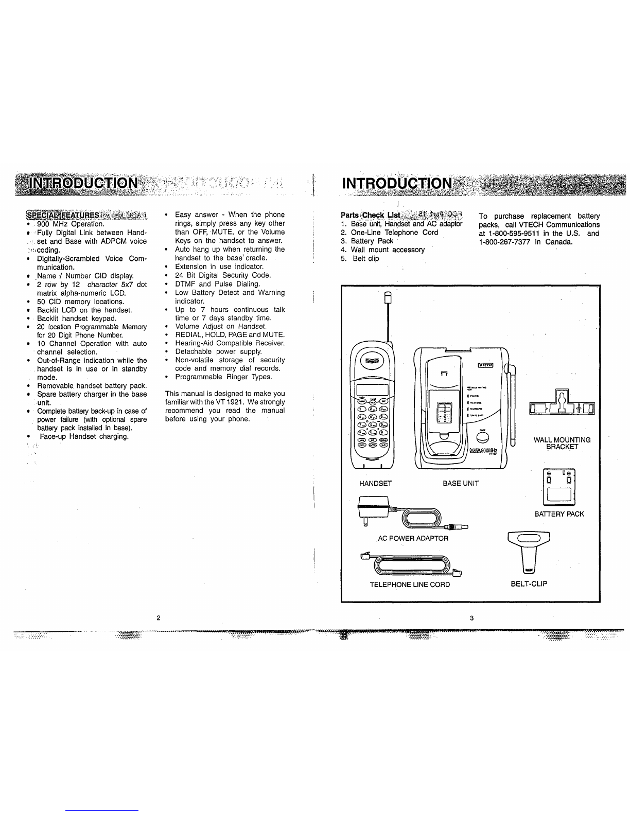
Parts Check List 3
.......................................
....................................
FCC AND IC REGULATIONS
.........
4
.......................................................................
.
IMPORTANT SAFETY INSTRUCTIONS
7
!'
...
I;
REPLACING THE BAlTERY PACK
..............................................................................
9
GETTING STARTED
.....................................................................................................
13
..........................................................................................................
"
WALL MOUNTING 15
.................................
....................................................................
THE LCD DISPLAY
..
16
':
;
'"THEHANDSET LAYOUT
.................................................................................................
-17
THE BASE UNIT LAYOUT
............................................................................................
-18
QUICK REFERENCE GUIDE
...................
...
...............................................................
19
BASIC OPERATION
.................................................................................................
21
............................................................................................
ADVANCED FUNCTIONS
22
CID WithcallWaiting
.......................................................................................................
22
Switching Calls
..............................................................................................................
22
Temporary Tone
....................................
....
.......................................................................
22
PrograinmingThe Ringer
................................................................................................
22
Changing Ringer Types
.....................................................................................................
22
CALL WAITING
.........................................................................................................
,.22
TEMPORARY TONE
......................................................................................................
22
Turning
Off
The Ringer
..........................
..
...................................................................
23
CheckingThe RingerType
..........................
..
................................................................
23
CLWDELKey Function
..........................
....
.................................................................
23
Advanced Dialing
.............................................................................................................
24
MEMORY DIALING
.......................................................................................................
25
....................................................................
StoringSpeed Dial Numbers
.....................
..
25
Dialing From Memory
.....................................................................................................
26
ChangingStored Numbers
....................
..
.......................................................................
26
DeletingStored Numbers
..................................................................................................
26
Storing Special Codes
......................................................................................................
27
...............................................................................................................
CID-CALLER ID
28
CID-CALLER ID
........................
..
................................................................................
..28
Receiving and Storing Calls
..............................................................................................
28
Dialing From CID Memory
...............................................................................................
28
Out Of Area Calls
...........................................................................................................
29
"PrivateuCalls
...............................................................................................................
29
Transmission Error
....................
....................
...................................................................
29
Reviewing Numbers
.......................................................................................................
30
Deleting Numbers
..........................................................................................................
31
ADDITIONAL OPERATING TIPS
................................................................................
32
.........................................................................................
MAINTENACE
....................
..
.33
....................................................................
IN
CASE OF DIFFICULTY
.......................
..
35
WARRANTY
....................................................................................................................
36
TECHNICAL SPECIFICATIONS
......................................................................................
37
Congratulations! You have purchased
one of the most sophisticatedcordless
telephones on the market! The
VT
1921 has been designed to offer a
new standard in cordless telephone
technology.
Unlike most other cordless phones,
the VT 1921digitizesyour voice using
advancedADPCMdigitalvoicecoding
to provide noise and distortion free
performance. In most conditions you
will not be able to te!l you are using
a cordless phone. Gone are the
annoyances of static, interference
and having to listen to other people's
conversationsonyourcordlessphone.
The VT 1921 scrambles your voice
before it transmits it. This allows you
the security of knowing that no one
can tune in and eavesdrop on your
conversations.
The VT 1921 decodes and displays
name and/or number Caller ID (CID)
informationwhere availableandwhen
subscribed to. The alpha-numeric
display can show both thename and
number of the calling party. Up to 24
namecharactersor 11phone number
digits can be displayed on the LCD.
With the VT 1921,the user can easily
answer a call by pressing any key
otherthantheOFF,MUTEorVOLUME
Keys. In addition, the handset keypad
and LCD illuminate while the handset
rings to signal an incoming call. This
is very useful in a dark environment.
The VT 1921 also provides a one-
way PageIFind. Pressing the base
PAGE key will cause the .handset to
ring in a manner which distinguishes
it from normal incoming ringing. This
can be usedto alert the handsetuser,
or to simply locate the handset in the
event that it is misplaced.
The VT 1921 uses special memory in
both the base and handset which is
not susceptible -to power failures.
This provides permanent storage of
a11 memory dial numbers, CID
information as well as the base and
handset security, codes.
When an optional battery pack is
installed,inthe base unit,the
VT
1921
uses this battery pack to provide
operational backup in case of power
failure. In this way you have access
to all normal phone functions during a
total power outage. Calls can still be
placed and received without
interruption. Morethan
5
hoursbackup
will be possible with a fully charged
battery pack in the base unit.
The
VT
1921informsyou that another
extension is currently in use on the
same phone line. The phone.willalso
alert you when you are Out of Range,
evenwhen you're notusingthe phone!