1
Caution! Read All Instructions and Warnings
Before Installation
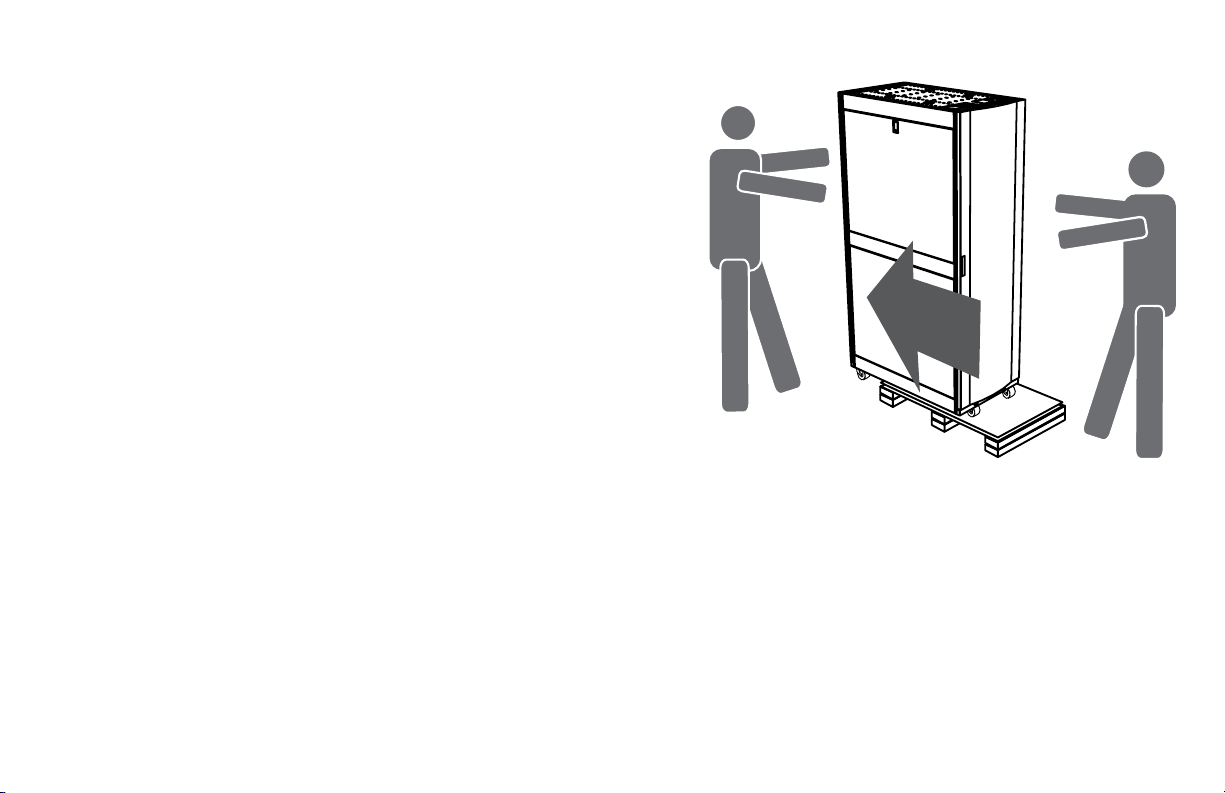
Warning: Rack enclosures can be extremely heavy.
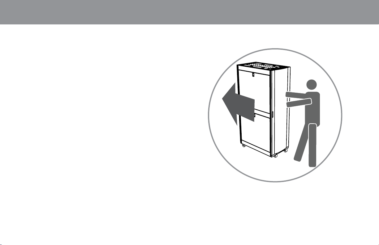
Do not attempt to unpack, move or install the
enclosure without assistance. Use extreme caution
when handling the enclosure and be sure to follow
all handling and installation instructions. Do not
attempt to install equipment without rst stabilizing
the enclosure.
Getting Started
The enclosure must be installed in a structurally
sound area that is able to bear the weight of the
enclosure, all the equipment that will be installed
in the enclosure and any other enclosures and/
or equipment that will be installed nearby. Before
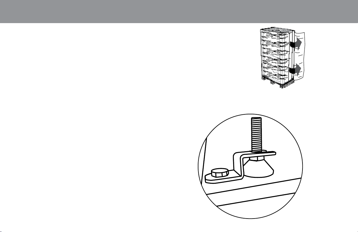
unpacking the enclosure, you should transport the
shipping container closer to the nal installation
location to minimize the distance you will need to
move the unit after the protective packaging has
been removed.
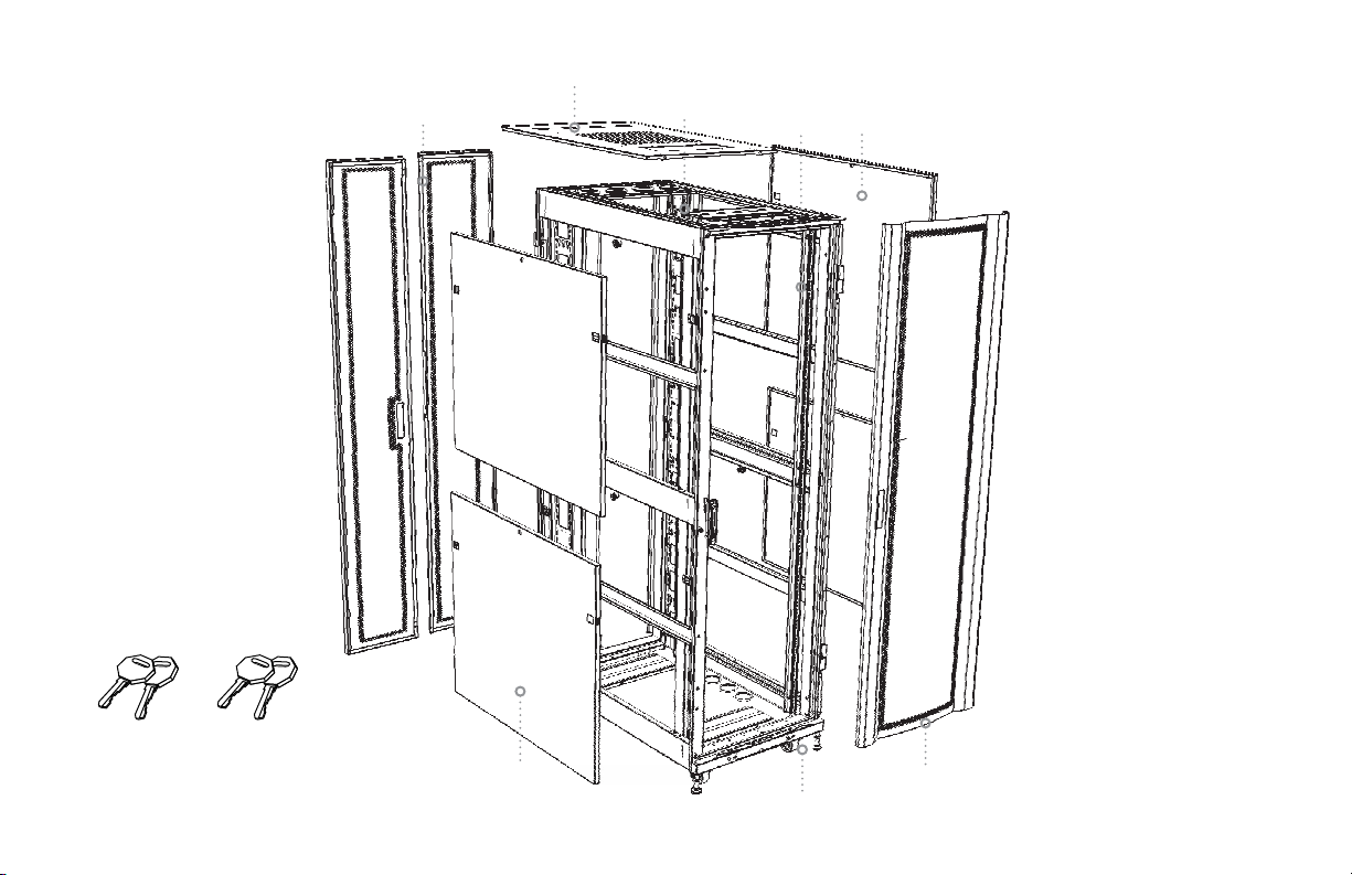
Included
• Cabinet
• 4 casters
• 4 bolt-down hardware
• 4 leveling feet
• 50 sets hardware M6 (screws/cage nuts)
Tools Required:
• open-end wrench • phillips-head screwdriver
• utility knife • carpenters level
Caution! Read All Instructions and Warnings
Before Installation
Warning: Rack enclosures can be extremely heavy.
Do not attempt to unpack, move or install the
enclosure without assistance. Use extreme caution
when handling the enclosure and be sure to follow
all handling and installation instructions. Do not
attempt to install equipment without rst stabilizing
the enclosure.
Getting Started
The enclosure must be installed in a structurally
sound area that is able to bear the weight of the
enclosure, all the equipment that will be installed
in the enclosure and any other enclosures and/
or equipment that will be installed nearby. Before
unpacking the enclosure, you should transport the
shipping container closer to the nal installation
location to minimize the distance you will need to
move the unit after the protective packaging has
been removed.
Included
• Cabinet
• 4 casters
• 4 bolt-down hardware
• 4 leveling feet
• 50 sets hardware M6 (screws/cage nuts)
Tools Required:
• open-end wrench • phillips-head screwdriver
• utility knife • carpenters level
Enclosure
Installation •Enclosure
Installation •Enclosure
Installation •Enclosure
Installation •Enclosure
Installation •Enclosure
Installation