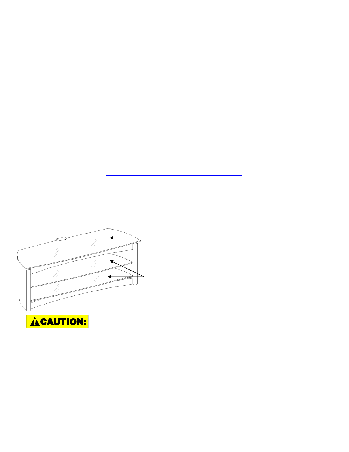
Bayside Furnishings Vision 3-in-1 TV Console User manual


Other Bayside Furnishings Indoor Furnishing manuals

Bayside Furnishings
Bayside Furnishings CORC-8B User manual

Bayside Furnishings
Bayside Furnishings CSC4836AC-2 User manual

Bayside Furnishings
Bayside Furnishings Metrex CORC-7 User manual

Bayside Furnishings
Bayside Furnishings CSC5430WD-3PC User manual

Bayside Furnishings
Bayside Furnishings CSC48WD-2PC User manual

Bayside Furnishings
Bayside Furnishings CSC9PD-4 User manual

Bayside Furnishings
Bayside Furnishings CSC9PD-6 User manual

Bayside Furnishings
Bayside Furnishings CSC7PCHD-1N User manual

Bayside Furnishings
Bayside Furnishings 9-Piece Dining Set User manual

Bayside Furnishings
Bayside Furnishings CUKGLBST-1 User manual

Bayside Furnishings
Bayside Furnishings Fontana FTN60C User manual

Bayside Furnishings
Bayside Furnishings PT3N1C-46-N User manual

Bayside Furnishings
Bayside Furnishings RHSPD-UK User manual

Bayside Furnishings
Bayside Furnishings Kavari 223243-30-00GT User manual

Bayside Furnishings
Bayside Furnishings SON3N1CGT User manual
Popular Indoor Furnishing manuals by other brands

Regency
Regency LWMS3015 Assembly instructions

Furniture of America
Furniture of America CM7751C Assembly instructions

Safavieh Furniture
Safavieh Furniture Estella CNS5731 manual

PLACES OF STYLE
PLACES OF STYLE Ovalfuss Assembly instruction

Trasman
Trasman 1138 Bo1 Assembly manual

Costway
Costway JV10856 manual


