Operation 4
0020230756_00 0020230738 Operating instructions 5
installation no longer provides sufficient excess energy, it
may be the case that the immersion heater circuit is oper-
ated for a maximum of 10 seconds with energy from the
energy supply company before the PV electrical immersion
heater is switched off.
If the PV electrical immersion heater has been switched,
it remains switched off for a minimum of 110, 170 or
230 seconds, depending on the power, before it can be
switched on again.
Example: Even if the Energy Manager reports a feed-in of
1000 W to the PV electrical immersion heater, the 1000 W
immersion heater circuit remains switched off for at least
170 seconds as soon as it is switched on and then off again,
before it can heat again.
For safety reasons, the Energy Manager must continuously
communicate with the PV electrical immersion heater via
the RS485 interface. If communication no longer takes
place after 10 seconds, the PV electrical immersion heater
switches the immersion heater circuits off and displays the
status "No connection" (operating status signal LED lights up
permanently in red).
3.4 CE label
The CE label shows that the products comply with the basic
requirements of the applicable directives as stated on the
identification plate.
The declaration of conformity can be viewed at the manufac-
turer's site.
4 Operation
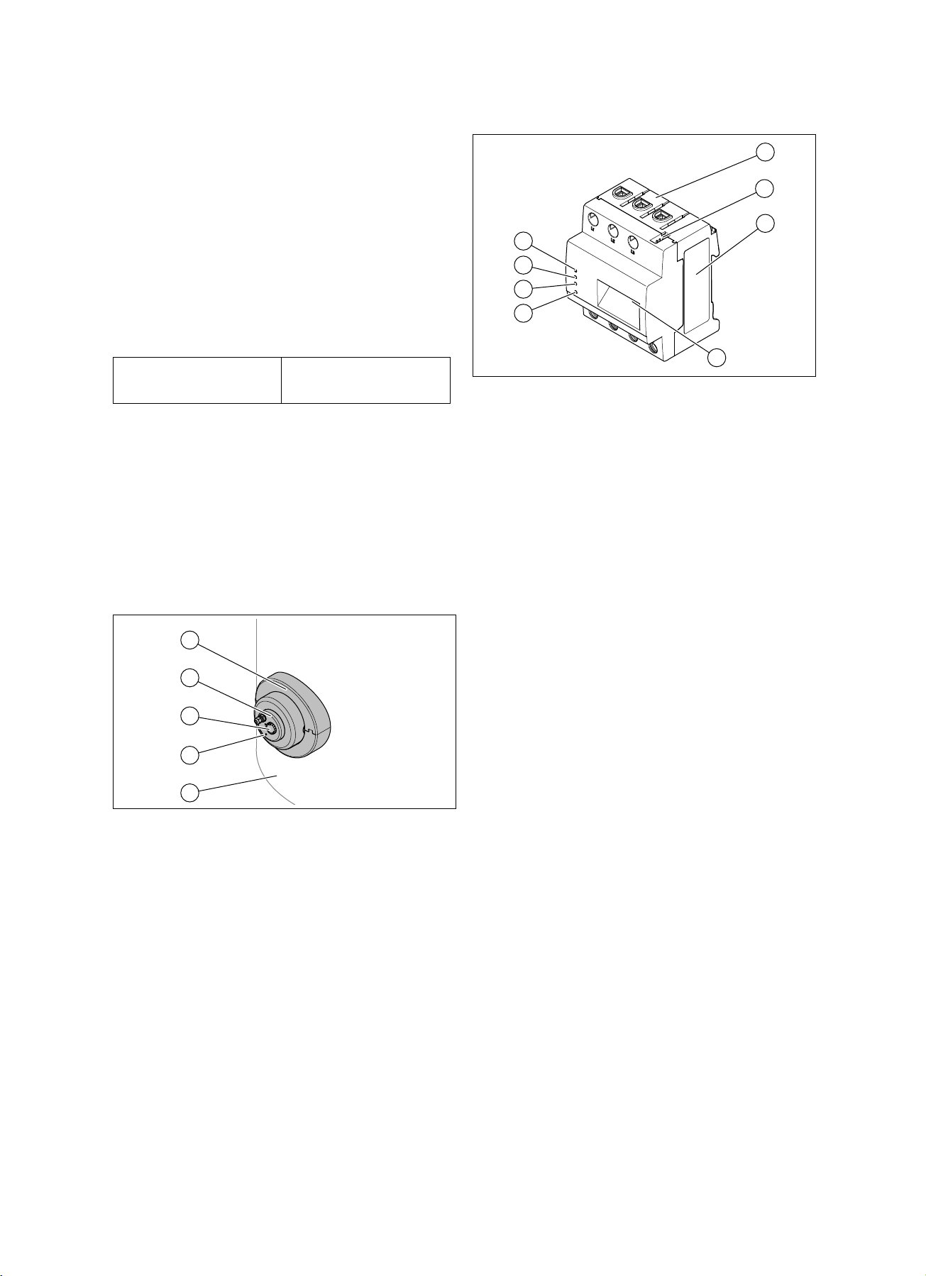
4.1 Overview of the setting control functions
Setting control position Function
OFF
The heating is not switched on
when there is a requirement
for the Energy Manager via the
RS485 interface. It is also not
switched on when the cylinder
temperature falls below the frost-
protection temperature.
Frost protection activated. Heat-
ing output is 0 W. If the cylinder
temperature falls below 4 °C
±3 K, the status display flashes
orange for 9 seconds. Pause.
The PV electrical immersion
heater heats with 500 W power
until the cylinder temperature of
8 °C ±3 K is exceeded.
The max. cylinder temperature
is limited to approx. 40 °C. Upon
request by the Energy Manager,
the PV electrical immersion
heater heats with the power
that is possible depending on
the excess electricity until the
maximum cylinder temperature
of 40 °C is reached.
Setting control position Function
The max. cylinder temperature
is limited to approx. 60 °C. Upon
request by the Energy Manager,
the PV electrical immersion
heater heats with the power
that is possible depending on
the excess electricity until the
maximum cylinder temperature
of 60 °C is reached.
The max. cylinder temperature
is limited to approx. 80 °C. Upon
request by the Energy Manager,
the PV electrical immersion
heater heats with the power
that is possible depending on
the excess electricity until the
maximum cylinder temperature
of 80 °C is reached.
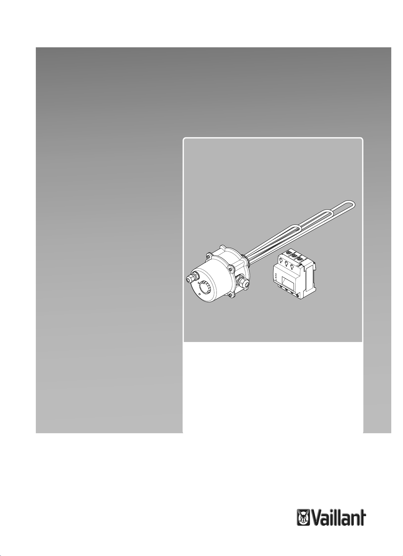
4.2 Flashing sequence for the PV electrical
immersion heater signal LED
Flashing
sequence
Meaning Required activity
Off The PV electrical immer-
sion heater is in the OFF
operating mode or no
mains voltage is present.
If required, switch
on the power
supply and the
PV electrical
immersion heater.
Flashes or
lights up per-
manently or-
ange
The PV electrical immer-
sion heater is in the frost
protection mode.
No activity re-
quired.
Lights up per-
manently
green or
flashes rhyth-
mically
Permanently on: Commu-
nication with the Energy
Manager is working. The
heating output is 0 W
(heating off).
Flashing rhythms display
the current heating out-
put. The flashing period is
approx. 10 seconds:
–1 x green flash, 9-
second pause: 500 W
–2 x green flash,
8-second pause:
1000 W
–3 x green flash,
7-second pause:
1500 W
–4 x green flash,
6-second pause:
2000 W
–5 x green flash,
5-second pause:
2500 W
–6 x green flash,
4-second pause:
3000 W
–7 x green flash,
3-second pause:
3500 W
No activity re-
quired.