VAN DER ENDE AIRMIX User manual

Airmix™ User Manual
Version: 2.0
Date: July 2020

Van der Ende Groep · Aartsdijkweg 23, 2676 LE, Maasdijk · Tel: 0174 515050
IBAN NL71 RABO 0340341610 · CC The Hague 27230471 · VAT-number NL8000.78.378.B01 · [email protected] · www.vanderendegroep.nl
Pagina 2 van 24
Foreword
This user guide is intended for users of the Airmix™ and technicians who install and maintain it. The
manual and operating instructions are bundled together in a single document.
Each chapter is numbered and, where necessary, divided into sections. The table of contents on page
2 contains an overview of the chapters and paragraphs, with references to page numbers.

Van der Ende Groep · Aartsdijkweg 23, 2676 LE, Maasdijk · Tel: 0174 515050
IBAN NL71 RABO 0340341610 · CC The Hague 27230471 · VAT-number NL8000.78.378.B01 · [email protected] · www.vanderendegroep.nl
Pagina 3 van 24
Contents
Foreword ...................................................................................................................................... 2
Contents ....................................................................................................................................... 3
1. Identification ............................................................................................................................. 4
1.1 General................................................................................................................................ 4
1.1.1 Description of the device ................................................................................................ 4
1.1.2 Specifications................................................................................................................. 4
1.1.3 Diagram of the system ................................................................................................... 5
1.2 Users................................................................................................................................... 6
1.3 Use ..................................................................................................................................... 6
1.4 Authorised servicers ............................................................................................................. 6
1.5 Operating environment ......................................................................................................... 6
1.6 Guarantee conditions............................................................................................................ 6
1.7 Relevant directives ............................................................................................................... 6
2. Description................................................................................................................................ 7
2.1 General................................................................................................................................ 7
2.2 Transportation and Storage .................................................................................................. 7
3. Safety instructions ..................................................................................................................... 7
4. Installation................................................................................................................................ 8
4.1 Contents of the installation kit............................................................................................... 8
4.2 Suspending the Airmix™ ....................................................................................................... 9
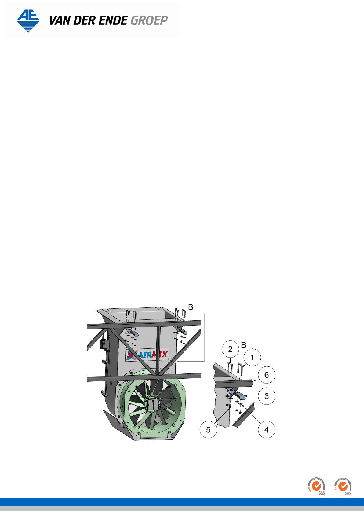
4.2.1 Mounting directly under the truss lattice .......................................................................... 9
4.2.1 Mounting with suspension brackets ................................................................................10
4.3 Attaching the fan.................................................................................................................11
4.4 Installing the extension........................................................................................................13
4.5 Installing the spacer ............................................................................................................14
4.6 Installing the valve position sensor .......................................................................................15
4.7 Modifying the screen cloth ...................................................................................................16
5. Connecting the thermostatic switch ...........................................................................................16
6. Operation/using for the first time...............................................................................................18
6.1 Gear-rack drive ...................................................................................................................18
7. Maintenance ............................................................................................................................19
8. Failures and repairs ..................................................................................................................19
9. Disassembly .............................................................................................................................19
10. Declaration of Conformity........................................................................................................20
Attachments ................................................................................................................................21
CE declaration concerning fan....................................................................................................22
CE declaration concerning linear drive ........................................................................................23
Note ............................................................................................................................................24

Van der Ende Groep · Aartsdijkweg 23, 2676 LE, Maasdijk · Tel: 0174 515050
IBAN NL71 RABO 0340341610 · CC The Hague 27230471 · VAT-number NL8000.78.378.B01 · [email protected] · www.vanderendegroep.nl
Pagina 4 van 24
1. Identification
This overview contains general information about the device. The purpose of this part is to indicate
the limits and overall operation of the device, and the areas it is used in.
1.1 General
1.1.1 Description of the device
The Airmix™ consists of a fan attached to an aluminium housing which is open at the top and fitted
with two valves at the rear. These valves are controlled by a gear-rack drive. The Airmix™ is equipped
with a power cord with a plug for the fan, and a power cord for the gear-rack drive. The Airmix™ has
no internal controls.
1.1.2 Specifications
General
Type
Airmix™
Maximum dimensions L x W x H
777 x 700 x 998 mm
Total weight
32 kg
Fan
Capacity
0.38 kW
Voltage
230 V, 50 Hz
Current
1.7 A
Circulation capacity
5800 m3/hour*
Ventilation capacity
5200 m3/hour*
Dust and water ingress protection
IP54
Insulation class
THCL 155
Power cord
5-m cord plus Type F earthed plug
Gear-rack drive
Capacity
1.5 W
Voltage
24 V AC 50/60 Hz. 24 V DC
Functional range
AC / DC 19.2 to 28.8 V
Duration
116 s
Dust and water ingress protection
IP54
Adjustment force
150 N
Power cord
3 x 0.75 mm25-m cable, without plug
Suction housing
Material
3-mm aluminium
Number of valves
2
Table 1 Specifications
* Measured without air guide plate and grille

Van der Ende Groep · Aartsdijkweg 23, 2676 LE, Maasdijk · Tel: 0174 515050
IBAN NL71 RABO 0340341610 · CC The Hague 27230471 · VAT-number NL8000.78.378.B01 · [email protected] · www.vanderendegroep.nl
Pagina 5 van 24
1.1.3 Diagram of the system
Diagram showing the main components, numbered and named.
No.
Designation
1
Airmix™ housing
2
Fan
3
Gear-rack drive
4
Upper valve
5
Lower valve
Figure 1 Schematic view of the Airmix™

Van der Ende Groep · Aartsdijkweg 23, 2676 LE, Maasdijk · Tel: 0174 515050
IBAN NL71 RABO 0340341610 · CC The Hague 27230471 · VAT-number NL8000.78.378.B01 · [email protected] · www.vanderendegroep.nl
Pagina 6 van 24
1.2 Users
Generally, the Airmix™ is not operated directly, but controlled by an operator or user via a control
box. These users or operators must be at least 18 years old, employed by the company where the
Airmix™ is installed, and designated by the management as competent and authorised to operate the
Airmix™.
All those who do not meet the above definition are unauthorised users, and these unauthorised users
may create unsafe situations or risks to themselves or others if they use the Airmix™.
1.3 Use
The Airmix™ is designed to mix hot humid air from cultivation areas with cool dry air from above the
screen cloth in a greenhouse. This circulates air horizontally, and improves the climate distribution in a
greenhouse.
The Airmix™ is not designed to be used for any other purposes than those described above, such as
transporting gases other than low-temperature air (-10 °C to + 50 °C).
1.4 Authorised servicers
The Airmix™ can be serviced by any maintenance company, but Van der Ende is recommended as this
company is familiar with every aspect of the device.
Periodic servicing helps avoid unnecessary costs or failures, and improves reliability.
1.5 Operating environment
Install the Airmix™ on the lowest shelf of the truss lattice. Make a hole in the screen cloth, and
connect this with the opening at the top of the aluminium housing. If the screen cloth is attached to
the upper tube of the truss lattice, use an extension to overcome the height difference. If the
greenhouse has a double screen cloth, install a spacer between the two screen cloths, then connect
this to the Airmix™.
The fan must be installed out of reach of those without special equipment, and the truss must be
strong enough to bear the weight of the fan.
The Airmix™ is not designed for use in any other environment than that described above. The
Airmix™ is not suitable for use in explosive environments.
1.6 Guarantee conditions
The unit is guaranteed for 6 months after first use.
If a claim is made under guarantee, the parts concerned must be presented to the manufacturer for
assessment.
The guarantee is void in the event of any of the following;
Improper use
Repeatedly ignoring the manufacturer’s or supplier’s advice
Unauthorised repair, maintenance or use
Use of inappropriate power supply connections
Use of the machine in an unsuitable environment
Intentional damage or modification of the machine
1.7 Relevant directives
The Airmix™ complies with the provisions in the following directives;
Machinery Directive 2006/42/EC
Low Voltage Directive 2006/95/EC
EMC Directive 2004/108/EC
The Airmix™ is classified as a Class I device according to the Low Voltage Directive.

Van der Ende Groep · Aartsdijkweg 23, 2676 LE, Maasdijk · Tel: 0174 515050
IBAN NL71 RABO 0340341610 · CC The Hague 27230471 · VAT-number NL8000.78.378.B01 · [email protected] · www.vanderendegroep.nl
Pagina 7 van 24
2. Description
2.1 General
The purpose of the Airmix ™ is to ventilate and dehumidify in an area with a closed screen cloth. The
Airmix™ sucks in air from above the screen, and blows it into the cultivation area below. The system
is actually multifunctional, as it also acts as a horizontal recirculation system. This method of
operation allows ventilation to be controlled, and the screen cloth to be kept closed for longer. The
advantage of this is that it is unnecessary to create a ‘slit’ in the screen when it is cold outside,
thereby preventing pockets of cold (unwanted air flows and temperature differences).
The Airmix™ is fitted with the same fan as the Enfan. The inlet side of this fan is attached to the
aluminium housing. Two valves are mounted in the housing, so air can be sucked in from both above
and below the screen cloth (Figure 2). When the valves are closed, the Airmix™ sucks in air from the
cultivation area, and acts as a horizontal recirculation system. If the valves are open, air is sucked in
from above the screen cloth. The Airmix™ can be used in greenhouses with either single-screen or
double-screen systems.
Since the valves are controlled by the climate computer, the correct proportion of air from above and
below the screen cloth can be obtained. This is controlled on the basis of relative humidity and
temperature.
The Airmix™ can be used where all kinds of vegetable, fruit and ornamental plants are cultivated.
Figure 2 Overview of valve positions
2.2 Transportation and Storage
The Airmix™ is delivered in two parts. It is only necessary to attach the fan to the aluminium housing,
after which the Airmix™ can be suspended.
3. Safety instructions
Always make sure that the plug of the Airmix™ is disconnected from the power supply before working
on it! This prevents the fan starting unexpectedly or unintentionally.
Do not connect the fan or the gear-rack drive to the power supply until assembly has been completed
and the system has been suspended.
Only use self-locking nuts to assemble and mount the Airmix™! Failure to do so may result in parts
vibrating loose and falling off.

Van der Ende Groep · Aartsdijkweg 23, 2676 LE, Maasdijk · Tel: 0174 515050
IBAN NL71 RABO 0340341610 · CC The Hague 27230471 · VAT-number NL8000.78.378.B01 · [email protected] · www.vanderendegroep.nl
Pagina 8 van 24
4. Installation
This chapter describes installing the Airmix™. The fan still has to be attached to the aluminium
housing. There is also an explanation of how to install the spacer and extension piece. Read the entire
manual before starting work.
4.1 Contents of the installation kit
Quantity
Description
Type
Airmix™
1
Fan
0.38 kW
230 V, 50 Hz
1.7 A
5,000 m3/hour
Insulation class IP 54
1
Power supply cable
5-m cord plus Type F earthed plug
1
Airmix™ (excluding fan)
Incl. gear-rack drive
24 V AC 50/60 Hz. 24 V DC, 1.5 W
operating range AC/DC 19.2 to 28.8 V
duration 116 s
IP54
torque 150 N
5-m 3 x 0.75 mm² cable without plug
8
Attachment material of fan to spacer
Lock nut and washer stainless steel M10
1
Attachment of Airmix™ to truss lattice
2 M8 U-clamps U50x50 or U60x55
4 M8 fender washers
4 M8 hexagonal lock nuts
2
3-mm padding strip
Aluminium strip 50x60x3mm
Extension
1
Extension
Customer-specific component. The length of the
extension depends on the height which has to be
bridged.
Spacer
1
Spacer
Customer-specific component. The length of the
spacer depends on the gap between the two
screen cloths.
1
Attachment of the spacer to the truss
lattice
2 M8 U-clamps U50x50 or U60x55
4 M8 fender washers
4 M8 hexagonal lock nuts
2
3-mm padding strip
Aluminium strip 50x60x3mm
Extra
1
Valve position sensor
600/1 KΩ incl.
2 M5 washers
2 M5 lock nuts
1
Connection of the valve position
sensor to the gear rack
2 Clamp incl.
1 M4x16 hexagonal bolt stainless steel
1 M5x30 hexagonal bolt stainless steel
1 M5x25 internal hexagonal countersunk bolt
stainless steel
2 M5 hexagonal lock nut stainless steel
4 M5 fender washer stainless steel
1 M4 hexagonal lock nut stainless steel
3 M4 fender washer stainless steel
1
Extended suspension bracket
2 extended suspension bracket incl.
4 M8x25 carriage bolt
4 M8 lock nuts
4 M8 washers
Table 2 Contents of the installation kit

Van der Ende Groep · Aartsdijkweg 23, 2676 LE, Maasdijk · Tel: 0174 515050
IBAN NL71 RABO 0340341610 · CC The Hague 27230471 · VAT-number NL8000.78.378.B01 · [email protected] · www.vanderendegroep.nl
Pagina 9 van 24
4.2 Suspending the Airmix™
4.2.1 Mounting directly under the truss lattice
It is easier to suspend the Airmix™ before attaching the fan to the aluminium housing, so only attach
the fan when the Airmix™ is already suspended. Proceed as follows:
choose a suitable location;
omake sure that any shrinkage of the screen cloth can be compensated by suspending
the Airmix™ in such a way that it can be shifted if necessary towards the centre of
the screen cloth. The degree of shrinkage varies according to the type and age of
cloth, but can reach 15 cm per 100 metres of screen cloth;
omake sure that no objects can obstruct the Airmix™ inlets;
othe fan must be kept of reach unless special equipment, such as a stepladder, is
used.
ocheck that the truss is in good condition;
ocheck if there is a socket less than 5 m away;
oMake sure the Airmix™ is attached to the correct side of the truss lattice. The
Airmix™ must be attached to the side of the truss lattice towards which the screen
cloth profile moves;
use proper tools and equipment;
make sure that the Airmix™ can be installed safely - get help if necessary;
what you will need:
o2 M8 U-clamps U50x50 or U60x55;
o4 M8 fender washers;
o4 M8 lock nuts;
assembly (see Figure 3);
obring the Airmix™ to the place reserved for it;
oattach the Airmix™ to the lower truss lattice (4) with two clamps (1), four M8 fender
washers (2) and four M8 lock nuts (3);
Figure 3 Attaching the Airmix™ to the truss lattice

Van der Ende Groep · Aartsdijkweg 23, 2676 LE, Maasdijk · Tel: 0174 515050
IBAN NL71 RABO 0340341610 · CC The Hague 27230471 · VAT-number NL8000.78.378.B01 · [email protected] · www.vanderendegroep.nl
Pagina 10 van 24
4.2.1 Mounting with suspension brackets
It is easier to suspend the Airmix™ in combination with the suspension brackets and mounted fan on
the aluminium housing. See chapter 4.3 “attaching the fan” for more information. When the fan is
mounded to the Airmix™ housing proceed as follows:
choose a suitable location;
omake sure that any shrinkage of the screen cloth can be compensated by suspending
the Airmix™ in such a way that it can be shifted if necessary towards the centre of
the screen cloth. The degree of shrinkage varies according to the type and age of
cloth, but can reach 15 cm per 100 metres of screen cloth;
omake sure that no objects can obstruct the Airmix™ inlets;
othe fan must be kept of reach unless special equipment, such as a stepladder, is
used.
ocheck that the truss is in good condition;
ocheck if there is a socket less than 5 m away;
oMake sure the Airmix™ is attached to the correct side of the truss lattice. The
Airmix™ must be attached to the side of the truss lattice towards which the screen
cloth profile moves;
use proper tools and equipment;
make sure that the Airmix™ can be installed safely - get help if necessary;
what you will need:
o2 Suspension bracket;
o2 M8 U-clamps U50x50 or U60x55;
o4 M8x25 Carriage bolt
o8 M8 fender washers;
o8 M8 lock nuts;
assembly (see Figure 4);
oThe holes, in the Airmix™ housing, for the carriage bolts (2) need to be drilled to
Ø11mm;
oAttach the two suspension brackets (3) with four carriage bolts (2), four M8 fender
washers (4) and four M8 lock nuts (5) to the Airmix™;
obring the Airmix™ to the place reserved for it;
oattach the Airmix™ with the suspension brackets (3) to the lower truss lattice (6) with
two clamps (1), four M8 fender washers (4) and four M8 lock nuts (5);
Figure 4 Mounting Airmix™ to suspension brackets

Van der Ende Groep · Aartsdijkweg 23, 2676 LE, Maasdijk · Tel: 0174 515050
IBAN NL71 RABO 0340341610 · CC The Hague 27230471 · VAT-number NL8000.78.378.B01 · [email protected] · www.vanderendegroep.nl
Pagina 11 van 24
4.3 Attaching the fan
After the Airmix™ housing has been suspended, the fan can be attached to it. It is more easy to
connect the power supply cable at the fan, before you attach the fan to the Airmix™ housing. Follow
the instructions in chapter 5. It is recommended that the supplied grille is mounted to the outlet side
of the fan. To attach the fan correctly, proceed as follows:
use proper tools and equipment;
make sure that the Airmix™ can be installed safely - get help if necessary;
what you will need:
o8 M10 washers;
o8 M10 lock nuts;
assembly (see Figure 5);
oplace the fan next to the Airmix™;
oattach the fan to the Airmix™ by inserting it over the protruding M10 threads. Then
secure the fan with the supplied washers (1) and lock nuts (2);
Figure 5 Attaching the fan to the Airmix™

Van der Ende Groep · Aartsdijkweg 23, 2676 LE, Maasdijk · Tel: 0174 515050
IBAN NL71 RABO 0340341610 · CC The Hague 27230471 · VAT-number NL8000.78.378.B01 · [email protected] · www.vanderendegroep.nl
Pagina 12 van 24
After the fan is attached to the Airmix™, level the Airmix™ by attaching and tensioning wires to the
first or second consecutive trellis (see Figure 6). Depending of the strength of the truss you can
decide to mount one or two wires. You need to adjust the angle of the Airmix™ so that is in parallel
with the screen support wires.
Figure 6 Levelling the Airmix™
Wire outlet
Drill a hole in fan housing for centre
the wire
Drill hole for wire through
casing
Connection wire suction side

Van der Ende Groep · Aartsdijkweg 23, 2676 LE, Maasdijk · Tel: 0174 515050
IBAN NL71 RABO 0340341610 · CC The Hague 27230471 · VAT-number NL8000.78.378.B01 · [email protected] · www.vanderendegroep.nl
Pagina 13 van 24
4.4 Installing the extension
If it is not possible to connect the opening on the top of the Airmix™ directly to the screen cloth, an
extension must be installed to bridge the gap. This procedure is described below.
use proper tools and equipment;
make sure that the extension can be installed safely - get help if necessary;
what you will need:
o4 self-tapping screws;
assembly (see Figure 7);
oInsert the extension (2) into the Airmix™;
oMake sure that the extension extends to the screen cloth;
oattach the extension to the Airmix™ using four self-tapping screws (two screws in the
front and two screws in the rear of the Airmix™);
Figure 7 Installing the extension

Van der Ende Groep · Aartsdijkweg 23, 2676 LE, Maasdijk · Tel: 0174 515050
IBAN NL71 RABO 0340341610 · CC The Hague 27230471 · VAT-number NL8000.78.378.B01 · [email protected] · www.vanderendegroep.nl
Pagina 14 van 24
4.5 Installing the spacer
If the greenhouse has a double-screen, the Airmix™ system will require an extra part, namely a
spacer. This must be placed between the two screen cloths so that the Airmix™ can extract air from
above the upper screen, otherwise the machine would suck in air from between the two screens. The
lower screen cloth must still be able to move between the Airmix™ housing and the spacer, so that it
can be opened and closed. To ensure that no air is sucked in between the Airmix™ and the spacer,
brush strips and PVC flaps must be mounted on the spacer. Mount the spacer as follows:
use proper tools and equipment;
make sure that the extension can be installed safely - get help if necessary;
what you will need:
o2 M8 U-clamps U50x50 or U60x55;
o4 M8 fender washers;
o4 M8 lock nuts;
o2 clamping strips;
o1 cuff;
o10 self-tapping screws;
assembly (see Figure 8);
oslide the cuff (2) over the spacer (1) and place the resulting piece next to the upper
truss lattice above the Airmix™ opening;
oAttach the spacer to the upper truss lattice with two clamps, four M8 washers and
four M8 lock nuts (as shown in Figure 3);
oSlide the cuff down to cover the gap between the Airmix™ and the spacer;
oAttach the cuff to the spacer using two clamping strips (3) and self-locking screws.
oCheck that the aluminium carriage of the screen cloth passes under the spacer.
N.B. There is a possibility to place a stainless steel shaft in the cuff for more strengthening. Contact
Van der Ende Groep for the possibilities.
Figure 8 Installing the spacer

Van der Ende Groep · Aartsdijkweg 23, 2676 LE, Maasdijk · Tel: 0174 515050
IBAN NL71 RABO 0340341610 · CC The Hague 27230471 · VAT-number NL8000.78.378.B01 · [email protected] · www.vanderendegroep.nl
Pagina 15 van 24
4.6 Installing the valve position sensor
The valves of the Airmix™ must be controlled by a climate computer, see chapter 6.1. One valve
position sensor must be installed per section on an Airmix™ to report the actual position of the valves
to the climate computer. In practice, a greenhouse might be divided into multiple sections, where
each section has its own climate control. That is why one Airmix™ in each section has to be equipped
with a valve position sensor. The valve position sensor must be mounted before the Airmix™ is
suspended. Mount the valve position detector as follows:
use proper tools and equipment;
make sure that the valve position sensor can be installed safely - get help if necessary;
Mounting the valve position sensor with vertical/open valves, the valves can be manually opened
if the drive is unblocked (see chapter 6.1 “Gear-rack drive” picture 3).
Drill two 6-mm holes in the Airmix™ housing , see figure 9;
Assemble the parts as shown in the figure below;
The drive must be mounted in the top hole of the linear rack;
Figure 9 Mounting valve position sensor

Van der Ende Groep · Aartsdijkweg 23, 2676 LE, Maasdijk · Tel: 0174 515050
IBAN NL71 RABO 0340341610 · CC The Hague 27230471 · VAT-number NL8000.78.378.B01 · [email protected] · www.vanderendegroep.nl
Pagina 16 van 24
4.7 Modifying the screen cloth
The Airmix™ system requires modifications to the screen cloth, since a hole must be made in it so
that the Airmix™ can draw in air from above. This hole must be at least as large as the opening of the
Airmix™, and reinforced with triple stitching. The hole could be strengthen by stitching a stainless
steel axis at the long side of the hole. For more info please contact Van der Ende Group or your
screen supplier.
5. Connecting the thermostatic switch
A thermostatic switch is built in to the winding of every fan as standard. When connected, this switch
turns the engine off if voltage levels are exceeded and the internal temperature rises above 100 °C.
The motor gets too hot if the fan becomes blocked, or similar.
Connecting the fan as shown in Figures 10 and Picture 1 increases its life span. The thermostatic
switch is connected in series with the phase. The red line in Picture 1 is the connection between TB
and U1.
PLEASE NOTE: This thermostatic switch has no hard reset, so when the engine has cooled
sufficiently it will restart. Therefore, always disconnect the plug from the power supply
during maintenance!
NB: an external protective device with a hard reset is available on request.
Figure 10 Wiring diagram
Picture 1 Connecting the thermostatic switch

Van der Ende Groep · Aartsdijkweg 23, 2676 LE, Maasdijk · Tel: 0174 515050
IBAN NL71 RABO 0340341610 · CC The Hague 27230471 · VAT-number NL8000.78.378.B01 · [email protected] · www.vanderendegroep.nl
Pagina 17 van 24
External protective devices are available for all types of fans. In combination with the internal
thermostatic switch, this protective device can turn off the installation via an alert and reset.
Figure 11 External protective device wiring diagram
Picture 2 External protective device

Van der Ende Groep · Aartsdijkweg 23, 2676 LE, Maasdijk · Tel: 0174 515050
IBAN NL71 RABO 0340341610 · CC The Hague 27230471 · VAT-number NL8000.78.378.B01 · [email protected] · www.vanderendegroep.nl
Pagina 18 van 24
6. Operation/using for the first time
Operating the fan of the Airmix™ is simple: if it is connected to the power supply it will start
ventilating, if it is disconnected it will stop ventilating. It is possible to set the speed by adjusting the
voltage at the plug with something like a control transformer, but this is not part of the Airmix™.
6.1 Gear-rack drive
The drive (Picture 3) of the valves must be controlled by the climate computer. A 3-core cable exits
the drive. Core number 1 is neutral, and cores number 2 and 3 respectively open and close the linear
gear-rack drive. 24 V AC 50/60 Hz. 24 V DC.
Picture 3 Gear-rack drive
Figure 12 Gear-rack drive
Connection diagram
Unlock button

Van der Ende Groep · Aartsdijkweg 23, 2676 LE, Maasdijk · Tel: 0174 515050
IBAN NL71 RABO 0340341610 · CC The Hague 27230471 · VAT-number NL8000.78.378.B01 · [email protected] · www.vanderendegroep.nl
Pagina 19 van 24
7. Maintenance
When servicing the Airmix™, the fan plug must be removed from the socket, and the drive
disconnected, to prevent unexpected and unwanted starting of the fan or linear drive.
The Airmix™ requires a minimum of maintenance:
Keep the inlet side of the fan free of foreign objects and dirt.
If the fan blades, fan housing, or aluminium housing of the Airmix™ are dirty, wipe down with a
damp cloth.
Replace the capacitor after 10,000 operating hours. This will help maintain the correct speed and
avoid excessive power consumption (reduced efficiency).
8. Failures and repairs
Experience has shown that failures are virtually inexistent. What can happen in practice is that the
thermal protection of the fan is triggered due to an internal defect, but if this does happen, it means
that the fan has reached the end of its service life and must be replaced.
If the Airmix™ valves do not move to the desired position, it means the linear gear-rack drive is
defective or a valve has jammed. Defective drives must be replaced. The valves can be manually
opened or closed if the drive is unblocked (see unblock button in Figure 8). This allows the position
where the valve is jammed to be determined and fixed.
9. Disassembly
Check that the plug is disconnected from the power supply and the linear drive is disconnected, to
prevent unexpected and unwanted starting of the fan or the valves opening or closing. Make sure the
workplace is safe, then remove the self-locking nuts of the U-clamps or the fan. Depending on what
has to be disassembled, the Airmix™ and/or fan can now be removed.

Van der Ende Groep · Aartsdijkweg 23, 2676 LE, Maasdijk · Tel: 0174 515050
IBAN NL71 RABO 0340341610 · CC The Hague 27230471 · VAT-number NL8000.78.378.B01 · [email protected] · www.vanderendegroep.nl
Pagina 20 van 24
10. Declaration of Conformity
EC DECLARATION OF CONFORMITY
(In accordance with Annex IIA of the Machinery Directive 2006/42/EC)
We,
declare, under our sole responsibility, that the following machine
to which this declaration relates is in conformity with the following directives;
It is also, where appropriate, in conformity with the following standards or other normative
documents;
n/a
Van der Ende Pompen
Aartsdijkweg 23
2676 LE Maasdijk
The Netherlands
Airmix™
Machinery Directive 2006/42/EC
Low Voltage Directive 2006/95/EC
EMC Directive 2004/108/EC
The Netherlands
Maasdijk
25 October 2019
L. van der Ende
Other manuals for AIRMIX
1
Table of contents
Other VAN DER ENDE Fan manuals
Popular Fan manuals by other brands

FUAVE
FUAVE SV7010 manual

Schako
Schako NOVENCO NovAx ACP Series Installation and Maintenance

Bathology
Bathology Atmospheric 310 Installation and operation manual

NuTone
NuTone 349BR instructions

Ameri-King
Ameri-King AK-950-F Series Installation and operation manual

Hunter
Hunter Trimaran installation manual

Forno
Forno Voce CF01566 instruction manual

Pinnacle
Pinnacle Protemp PT-20S-DDF User's manual and operating instructions

Nibe
Nibe ESV 20 installation instructions

Minuteman
Minuteman C46310-00 manual

Maico
Maico DZQ Ex e Series Installation and operating instructions

Vortice
Vortice LINEO 100-160 ES Instruction booklet