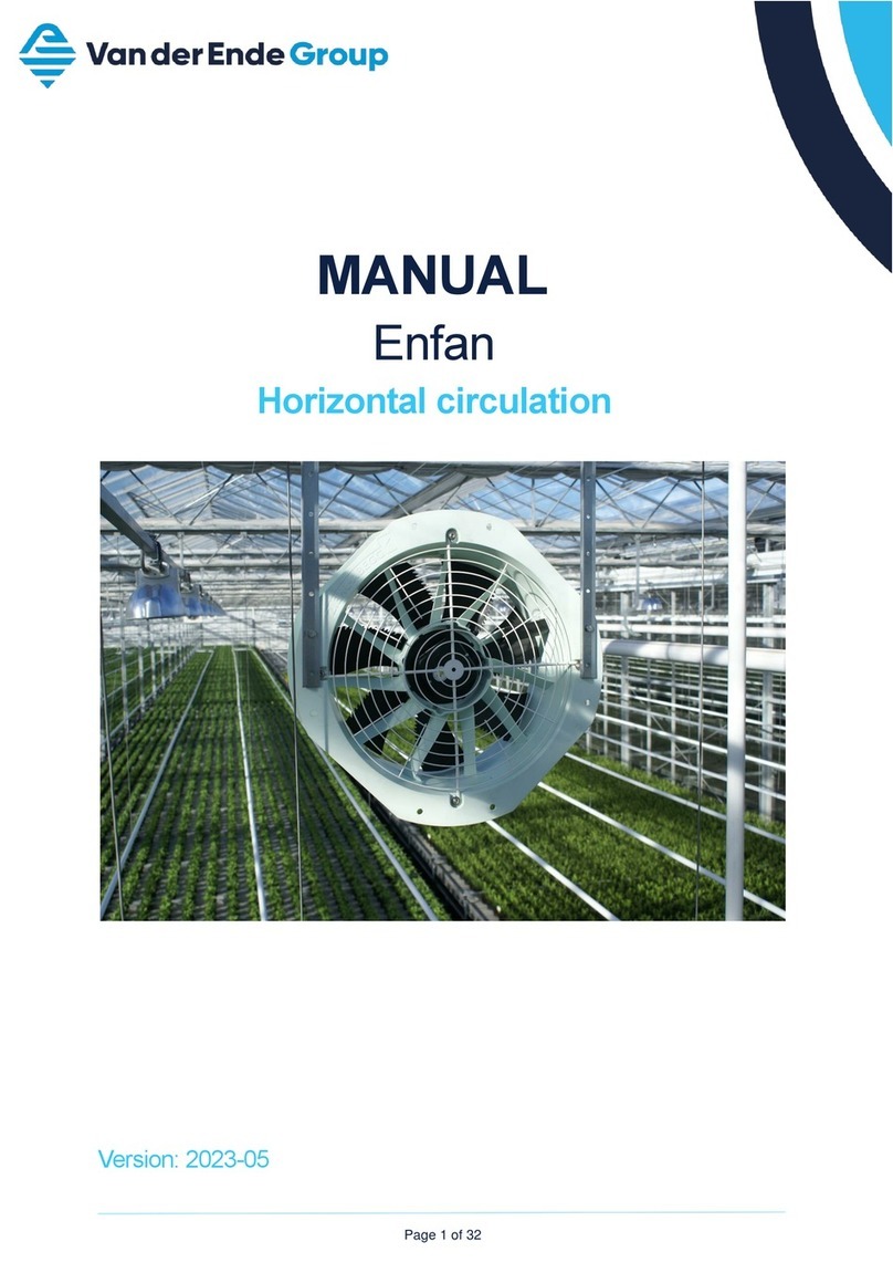
VAN DER ENDE Airmix G User manual

Airmix model G
Installation Manual
Version: 1.7
Date: February 2022

Van der Ende Groep · Aartsdijkweg 23, 2676 LE, Maasdijk · Tel. 0174 515050
IBAN NL71 RABO 0340341610 · KvK Den Haag 27230471 · Btw-nummer NL8000.78.378.B01 · [email protected] · www.vanderendegroep.nl
Page 2 of 32
Foreword
This user manual is intended for users of the Airmix™ model G and for technicians who install and
maintain it. The user instructions and operating instructions are combined in a single document. The
manual was produced by the inventor, Van der Ende Group (hereafter referred to as VDEG).
Each chapter is numbered and, where necessary, divided into sections. The table of contents on page
4 gives an overview of the chapters and sections, with references to the page numbers. There are
numbers in the whole assembly manual referring to the parts described in the pictures.

Van der Ende Groep · Aartsdijkweg 23, 2676 LE, Maasdijk · Tel. 0174 515050
IBAN NL71 RABO 0340341610 · KvK Den Haag 27230471 · Btw-nummer NL8000.78.378.B01 · [email protected] · www.vanderendegroep.nl
Page 3 of 32
Contents
Foreword ...................................................................................................................................... 2
Contents ....................................................................................................................................... 3
1Identification .......................................................................................................................... 4
1.1 General .......................................................................................................................... 4
1.1.1 Description of the system ............................................................................................ 4
1.1.2 Specifications.............................................................................................................. 4
1.1.3 Diagram of the system ................................................................................................ 5
1.2 Users ............................................................................................................................. 6
1.3 Use................................................................................................................................ 6
1.4 Authorised servicers........................................................................................................ 6
1.5 Media............................................................................................................................. 6
1.6 Operating environment ................................................................................................... 6
1.7 Guarantee conditions ...................................................................................................... 6
1.8 Relevant directives.......................................................................................................... 6
2Description............................................................................................................................. 7
2.1 General .......................................................................................................................... 7
2.2 Transport and storage .................................................................................................... 7
3Safety instructions .................................................................................................................. 8
4Installation ............................................................................................................................. 9
4.1 Contents of the installation kit ......................................................................................... 9
4.2 Suspending the Airmix™model G ...................................................................................11
4.2.1 Installing the attachment profiles and Airmix™model G ...............................................11
4.2.2 Installing the condensate plate and fan .......................................................................15
4.2.3 Installing the extension ..............................................................................................16
4.2.4 Installing the valve position sensor..............................................................................18
4.3 Air flow guide plates ......................................................................................................20
4.3.1 Configuration of the air flow guide plates ....................................................................20
4.3.2 Assembling the air flow guide plates ...........................................................................21
4.4 Modifying the screen......................................................................................................23
5Connecting the thermostatic switch ........................................................................................24
6Operation/using for the first time............................................................................................25
6.1 Connection diagram fan .................................................................................................25
6.1.1 Connection diagram ZN045 AC fan 230 V ~1 50 Hz......................................................25
6.1.2 6.1.2 Connection diagram ZN045 AC fan 230/400V D/Y ~3 50 Hz .................................25
6.1.3 6.1.3 Connection diagram ZN045 EC-fan 200-277 V AC ~1 50/60 Hz ............................25
6.2 Valve actuator ...............................................................................................................26
6.3 Connection diagram valve position sensor .......................................................................26
7Maintenance..........................................................................................................................27
8Failures and repairs ...............................................................................................................27
9Disassembly ..........................................................................................................................27
10 Declaration of Conformity ..................................................................................................28
Attachments ................................................................................................................................29
CE declaration for fan................................................................................................................30
CE declaration for gear-rack drive ..............................................................................................31
Note ............................................................................................................................................32

Van der Ende Groep · Aartsdijkweg 23, 2676 LE, Maasdijk · Tel. 0174 515050
IBAN NL71 RABO 0340341610 · KvK Den Haag 27230471 · Btw-nummer NL8000.78.378.B01 · [email protected] · www.vanderendegroep.nl
Page 4 of 32
1Identification
This overview contains general information about the device. The purpose of this chapter is to indicate
the limits and overall operation of the device, and the areas in which it is used.
1.1 General
1.1.1 Description of the system
The Airmix™ consists of a fan attached to an aluminum housing, which is open at the top and has
three valves at the rear. The Airmix™ model G needs attachment profile for mounting the Airmix™ at
a truss. The valves are controlled with a gear-rack drive. The Airmix™ has a power cord with a plug
for the fan (only the 50Hz variant) and a power cord for the gear-rack drive. The Airmix™ has no
internal controls.
1.1.2 Specifications
General
Type
Airmix™ model G
Maximum dimensions L x W x H
1270 x 630 x 1005 mm
Total weight
approx. 38 kg
Fan
50Hz AC
50/60Hz EC
60Hz AC
Power
0.38 kW
0.42 kW
0.24 kW
Voltage
230 V ~1 or 400 V ~3
200-277 V ~1
230 V ~1
Rotational speed
1250 rpm
1470 rpm**
960 rpm
Current
1.7 A
2.1 –1.5 A
1.05 A
Circulation capacity
5800 m3/hour*
5800 m3/hour**
5060 m3/hour*
Ventilation capacity
5200 m3/hour*
5200 m3/hour**
4400 m3/hour*
Dust and water ingress protection
IP54
IP54
IP54
Insulation class
THCL155
THCL155
THCL155
Power cord
5 m cord plus Type F
earthed plug
None
None
Certification
CE marking, EAC
CE marking, EAC,
cURus (E347018
ZB-155)
CE marking, EAC,
cURus (E111399
ZA-155)
Gear-rack drive
Power
1.5 W
Voltage
24 V AC 50/60 Hz 24 V DC
Functional range
AC/DC 19.2 to 28.8 V
Duration
116 sec
Dust and water ingress protection
IP54
Adjustment force
150 N
Power cord
5 m cable 3 x 0.75 mm2, without plug
Certification
CE marking, cULus (E108966)
Airmix™ housing
Material
Aluminum 2/3 mm
Number of valves
3
Table 1 Specifications
* Measured without air guide plate and grille, and depending on pressure difference.
** The EC fan has a nominal rotational speed of 1470 rpm. A rotational speed of 1250 rpm gives a
ventilation capacity of 5200 m3/hour. The installation drawings and calculations are based on this
rotational speed and ventilation capacity as standard. The EC fan is a fan with internal control. The EC
fan is supplied as standard on the basis of factory settings and non-addressed.

Van der Ende Groep · Aartsdijkweg 23, 2676 LE, Maasdijk · Tel. 0174 515050
IBAN NL71 RABO 0340341610 · KvK Den Haag 27230471 · Btw-nummer NL8000.78.378.B01 · [email protected] · www.vanderendegroep.nl
Page 5 of 32
1.1.3 Diagram of the system
Diagram showing the main components, numbered and named.
Figure 1 Schematic diagram of the Airmix™
No.
Name
1
Cover plate
2
Aluminum attachment profile
3
Extension duct (optional)
4
End plate
5
Valve
6
Truss
7
Airmix™housing
8
Fan
9
Gear-rack drive
10
Condensate plate (optional)
Figure 2: Parts of the Airmix model G

Van der Ende Groep · Aartsdijkweg 23, 2676 LE, Maasdijk · Tel. 0174 515050
IBAN NL71 RABO 0340341610 · KvK Den Haag 27230471 · Btw-nummer NL8000.78.378.B01 · [email protected] · www.vanderendegroep.nl
Page 6 of 32
1.2 Users
In principle, the Airmix™ is not operated directly, but only controlled externally by an operator or
user. These users must be at least 18 years old, employed by the company where the Airmix™ is
installed, and designated by the management as competent and authorised to operate the Airmix™.
All those who do not meet the above definition are unauthorised users, and these unauthorised users
may create unsafe situations or risks to themselves or others if they use the Airmix™.
1.3 Use
The Airmix™ is designed to mix warm, humid air from the growing area in a greenhouse with cold,
dry air from above the screen. This circulates air horizontally, and improves the climate distribution in
a greenhouse.
The Airmix™ is not designed to be used for any other purposes than those described above, such as
transferring gases other than low-temperature air (-30°C to +50°C).
1.4 Authorised servicers
The Airmix™ can be serviced by any maintenance company, but VDEG is recommended. Periodic
servicing helps to avoid unnecessary costs or failures, and improves reliability.
1.5 Media
Placing an image/comment in relation to the Enmix should always be discussed in advance with the
producer/supplier. If this is not observed, any consequential damage can be recovered from this
person/company.
1.6 Operating environment
The Airmix™ must be attached to the truss with attachment profiles in a greenhouse. The minimum
environmental temperature is -30°C and the maximum environmental temperature is 50°C.
The fan must be installed out of reach of people without special equipment (such as a stepladder or
aerial platform) and the truss must be strong enough to bear the weight of the fan.
The Airmix™ is not designed for use in any other environment than that described above. The
Airmix™ is not suitable for use in explosive environments.
1.7 Guarantee conditions
The unit is guaranteed for 6 months after first use.
If a claim is made under guarantee, the parts concerned must be presented to the manufacturer for
assessment.
The guarantee is void in the event of one or more of the following:
•Improper use
•Repeatedly ignoring the manufacturer’s or supplier’s advice
•Unauthorised repair, maintenance or use
•Use of inappropriate power supply connections
•Use of the machine in an unsuitable environment
•Intentional damage or modification of the machine
1.8 Relevant directives
The Airmix™ complies with the provisions of the following directives:
•Machinery Directive 2006/42/EC
•Low Voltage Directive 2006/95/EC
•EMC Directive 2004/108/EC
The Airmix™ is classified as a Class I device according to the Low Voltage Directive.

Van der Ende Groep · Aartsdijkweg 23, 2676 LE, Maasdijk · Tel. 0174 515050
IBAN NL71 RABO 0340341610 · KvK Den Haag 27230471 · Btw-nummer NL8000.78.378.B01 · [email protected] · www.vanderendegroep.nl
Page 7 of 32
2Description
2.1 General
The purpose of the Airmix™is to ventilate and dehumidify in an area with a closed screen. The
Airmix™ takes in air from above the screen, and blows it into the growing area below. The system is
actually multifunctional, as it also acts as a horizontal recirculation system. This method of operation
allows ventilation to be controlled, and the screen to be kept closed for longer. The advantage of this
is that it is unnecessary to create a ‘slit’ in the screen when it is cold outside, thereby preventing cold
downdraughts (unwanted air flows and temperature differences).
The Airmix™ is fitted with the same fan as the Enfan. The intake side of this fan is attached to the
aluminum housing. Three valves are mounted in the housing, so the air can be drawn in from both
above and below the screen. When the valves are closed, the Airmix™ draws air from the growing
area, and acts as a horizontal recirculation system. If the valves are open, the air is drawn in from
above the screen. The Airmix™ can be used in combination with all kinds of screen systems.
The valves are controlled by the climate computer, which means that the right mixture of air from
above and below the screen can be obtained. This is controlled on the basis of relative humidity,
absolute humidity and/or temperature.
The Airmix™can be used where all kinds of vegetable, fruit and ornamental plants are grown.
2.2 Transport and storage
The Airmix™ is delivered to customers in the following separate parts:
Part:
Number in Figure 1
Aluminum attachment profile
2
Airmix™ housing, including valves and gear-rack drive
3, 4 & 6
End plates
5
Cover plates
7
Fan
8
Extension
9
Condensate plate (optional)
10
Attachment bracket for air guide plate (optional)
-
Air guide plate (optional)
-
Valve position sensor
-
Attachment materials
-
Power cord for fan (only for 50Hz AC variant)
-
Figure 3: Delivered parts for Airmix model G

Van der Ende Groep · Aartsdijkweg 23, 2676 LE, Maasdijk · Tel. 0174 515050
IBAN NL71 RABO 0340341610 · KvK Den Haag 27230471 · Btw-nummer NL8000.78.378.B01 · [email protected] · www.vanderendegroep.nl
Page 8 of 32
3Safety instructions
Always make sure that the fan is unplugged at the socket before starting to work on the Airmix™!
This will prevent the fan from starting unexpectedly and/or unintentionally.
Do not connect the fan or the gear-rack drive to the power supply until assembly has been completed
and the system has been installed.
The regulations below are applicable to the Airmix model G.
Safety symbol
Description
Automatic starting machine!
Electric voltage present!
Danger of falling!
Rotating parts!
Reading instructions obligated!
Figure 4: safety instructions and possible danger applicable to the Airmix model G

Van der Ende Groep · Aartsdijkweg 23, 2676 LE, Maasdijk · Tel. 0174 515050
IBAN NL71 RABO 0340341610 · KvK Den Haag 27230471 · Btw-nummer NL8000.78.378.B01 · [email protected] · www.vanderendegroep.nl
Page 9 of 32
4Installation
This chapter describes how the Airmix™ must be installed. You must read the entire manual before
starting on the installation.
4.1 Contents of the installation kit
Quantity
Description
Contents
Airmix™ model G
1
Airmix™ model G
-Housing excl. fan, incl. valves and gear-
rack drive
1
Fan
1
Power cord for fan (only for 50Hz
variant)
-5m cord plus Type F earthed plug
1
Attachment materials for attaching
fan to spacer
-8 pcs. M10 hexagonal lock nuts
-8 pcs. M10 washers
2
Aluminum attachment profile
1
Connection set
-2 pcs. end plates
-4 pcs. Slide-in bracket for end plate
-2 pcs. cover plates
-2 pcs. plugs ¼’’
-1 pcs. profile connector
-2 pcs. mounting strips
-10 pcs. M8x16 hexagonal bolts
-8 pcs. M5 fender washers
-6 pcs. M8 fender washers
-8 pcs. M8 washers
-2 pcs. M6x12 set screws, hexagon socket
-12 pcs. metal screws 4,8x16
-14 pcs. metal screws with tapping point
4,8x13
Extension
1
Extension
Customer-specific component. The length of the
extension depends on the height that has to be
bridged
2
Aluminum attachment profile
1
Connection set
-2 pcs. end plates
-4 pcs. Slide-in bracket for end plate
-2 pcs. cover plates
-2 pcs. plugs ¼’’
-1 pcs. profile connector
-2 pcs. mounting strips
-10 pcs. M8x16 hexagonal bolts
-8 pcs. M5 fender washers
-6 pcs. M8 fender washers
-8 pcs. M8 washers
-2 pcs. M6x12 set screws, hexagon socket
-12 pcs. metal screws 4,8x16
-14 pcs. metal screws with tapping point
4,8x13
Table 2 Contents of the installation kit

Van der Ende Groep · Aartsdijkweg 23, 2676 LE, Maasdijk · Tel. 0174 515050
IBAN NL71 RABO 0340341610 · KvK Den Haag 27230471 · Btw-nummer NL8000.78.378.B01 · [email protected] · www.vanderendegroep.nl
Page 10 of 32
Accessories
1
Valve position sensor model G
600/1KΩ incl. attachment materials
1
Condensate drip tray
-1 pcs. condensate drip tray
-2 pcs. M10x25 hexagonal bolts
-2 pcs. M10 hexagonal nuts
-4 pcs. M10 washers
Options (content for one piece)
..
Air guide plate
-1 pcs. air guide plate
-3 pcs. M5x16 hexagonal bolts
-6 pcs. M5 washers
-3 pcs. M5 hexagonal nuts
..
Attachment bracket for air guide plate
-1 pcs. attachment bracket
-4 pcs. M10x25 hexagonal bolts
-8 pcs. M10 washers
-4 pcs. hexagonal nuts

Van der Ende Groep · Aartsdijkweg 23, 2676 LE, Maasdijk · Tel. 0174 515050
IBAN NL71 RABO 0340341610 · KvK Den Haag 27230471 · Btw-nummer NL8000.78.378.B01 · [email protected] · www.vanderendegroep.nl
Page 11 of 32
4.2 Suspending the Airmix™model G
This chapter describes the sequence of steps that must be taken when suspending the Airmix™model
G. You start by installing the aluminum attachment profiles, then the Airmix™housing is placed
between the attachment profiles. The fan and the condensate drip tray are then attached to the
housing. Always install the Airmix™model G in consultation with the screen installation technician.
The minimum equipment required is shown for each step.
4.2.1 Installing the attachment profiles and Airmix™model G
-Choose a suitable location:
ouse the installation diagram that was supplied by VDEG and/or your installation
technician;
omake sure that no objects are in the way;
omake sure that no objects can obstruct the Airmix™inlets and outlet;
othe fan must be installed out of reach of people without special equipment (such as a
stepladder);
ocheck that the truss is in good condition;
ocheck that there is an electrical connection less than 5 metres away;
-make sure you have the proper tools and equipment (enough for each person):
Quantity
Description
1
Battery impact wrench
1
Torx 25 bit (in impact wrench)
1
8mm socket bit (in impact wrench)
1
13mm open-ended wrench or socket wrench
1
16mm open-ended wrench
1
3mm hex key
-make sure that the Airmix™can be installed safely; two people are needed for installation,
with one person at height for each lattice truss;
-what you will need for each Airmix™:
Quantity
Description
No. In Figure
5 to 6
Article no. VDEG
1
Airmix model G
15
720052xx
2
Endplate
5
55014310
4
Slide-in bracket for end plate
11
55014380
2
Aluminum attachment profiles
2
580201xx
2
Aluminum cover plate
14
55014330
2
Mounting strips
3
55014320
1
Stainless steel profile connector
17
55014340
2
Stainless steel set screws, hexagon
socket m6x12
4
57023510
10
Stainless steel bolt m8x16
9
57005920
8
Stainless steel fender washer m5
7
57000120
6
Stainless steel fender washer m8
13
57000140
8
Stainless steel washer m8
10
57001140
4
Stainless steel self-locking nut m8
12
57004140
12
Metal screw 4,8x16
6
56033790
17
Metal screw with tapping point 4,8x13
8
56042760
2
Stainless steel plug ¼’’
16
68032415

Van der Ende Groep · Aartsdijkweg 23, 2676 LE, Maasdijk · Tel. 0174 515050
IBAN NL71 RABO 0340341610 · KvK Den Haag 27230471 · Btw-nummer NL8000.78.378.B01 · [email protected] · www.vanderendegroep.nl
Page 12 of 32
-fit a mounting strip (3) with an M6x12 set screw (4) in the groove of the profile (2), the first
M8 tapped hole 210mm from the end of the profile; tighten the set screw; do this for two
profiles. See Figure 5:
Figure 5 Mounting strip
-Insert a ¼’’ plug (20) in the end plates;
-Attach two attachment profiles (2) into one end plate (5) with six metal screws 4,8x16 (6).
Make sure the holes of the end plate and attachment profiles line up nicely and look if there is
no space left between the attachment profiles and the endplate.
oUse max. 150 Nm to put the metal screws 4,8x16 (6) into the attachment profiles.
Otherwise the screw could break or the aluminum wears out.
-put two 4,8x13 metal screws with tapping point (8) with corresponding fender washers m5 (7)
through the slotted holes in the side of the end plate (5) and into the aluminum attachment
profiles. Put the metal screws into the middle of the slotted hole.
Figure 6: mounting the metal screws into the end plate

Van der Ende Groep · Aartsdijkweg 23, 2676 LE, Maasdijk · Tel. 0174 515050
IBAN NL71 RABO 0340341610 · KvK Den Haag 27230471 · Btw-nummer NL8000.78.378.B01 · [email protected] · www.vanderendegroep.nl
Page 13 of 32
-fit two cover plates, lying onto each other (14), in the profile;
-Mount the second end plate with six 4,8x16 metal screws (6). Don’t screw the metal screws
fully fixed so there is some movement into the Airmix™ housing left.
-Place two 4,8x13 metal screws with tapping point (8) with corresponding fender washers m5
(7) into the second end plate. Don’t screw the metal screws fully fixed too so there is space
left to fine tune the end plate against the lattice (1).
-slide the Airmix™housing (23) between the profiles up to the end plate; attach it with six
M8x16 hexagonal bolts (9) and six M8 fender washers (13);
-put the cover plates in position and attach to each other with a 4.8x13 metal screw with
tapping point (8);
-lift the whole unit to the lattice and slide four Slide-in brackets (11) through the top of both
end plates so these Slide-in brackets rest on the lattice.
oMake sure the correct right slot is used for the Slide-in brackets. This is important for
the height related to the screen. See Figure 7.
-Make sure the end plate (5) is fully against the lattice. If so, connect the Slide-in brackets to
the end plate using one m8x16 stainless steel bolt (9), two washers m8 (10) and one self-
locking nut m8 (12).
-Connect the Slide-in brackets (11) to the lattice (1) with two metal screws with tapping point
4,8x13 (8).
-put the profile connector (17) in place, by turning it in the groove of the profiles, under the
overlap of the cover plates.
Figure 7: mounting the Slide-in brackets into the end plate

Van der Ende Groep · Aartsdijkweg 23, 2676 LE, Maasdijk · Tel. 0174 515050
IBAN NL71 RABO 0340341610 · KvK Den Haag 27230471 · Btw-nummer NL8000.78.378.B01 · [email protected] · www.vanderendegroep.nl
Page 14 of 32
Figure 8 Installing the Airmix
Figure 9 Profile connector and cover plates

Van der Ende Groep · Aartsdijkweg 23, 2676 LE, Maasdijk · Tel. 0174 515050
IBAN NL71 RABO 0340341610 · KvK Den Haag 27230471 · Btw-nummer NL8000.78.378.B01 · [email protected] · www.vanderendegroep.nl
Page 15 of 32
4.2.2 Installing the condensate plate and fan
After the Airmix housing has been suspended, the condensate drip tray and the fan can be attached
to it. Depending on the type of fan, it is best to prepare this first; see chapter 6. To attach the fan and
condensate plate correctly, go through the following steps:
-make sure you have the proper tools and equipment:
Quantity
Description
2
17mm open-ended wrench or socket wrench
-make sure that the fan can be installed safely –get help if necessary;
-what you will need for each Airmix:
Quantity
Description
No. in
Figure 10
Article no. VDEG
1
Fan
21
720034XX
1
Condensate drip plate
22
72005120
8
m10 self-locking nut
23
56016220
12
m10 washer
24
56019220
2
m10x25 bolt
25
56013230
2
m10 nut st vz
26
56015220
-Figure 10);
-attach the fan (21) to the Airmix housing by inserting it over the protruding M10 threads;
position the fan with the cable gland connection facing downward;
-secure the fan to the upper six M10 threads with six M10 washers (24) and six M10 self-
locking nuts (23);
-attach the condensate plate (22) to the Airmix housing by inserting it over the protruding M10
threads;
-secure the condensate plate to the lower two M10 threads with two M10 washers (24) and
two M10 nuts (not self-locking nuts) (26);.
-Secure the condensate plate to the fan with two M10x25 bolts (25), four M10 washers (24)
and two M10 self-locking nuts (23).
Figure 10 Installing the fan

Van der Ende Groep · Aartsdijkweg 23, 2676 LE, Maasdijk · Tel. 0174 515050
IBAN NL71 RABO 0340341610 · KvK Den Haag 27230471 · Btw-nummer NL8000.78.378.B01 · [email protected] · www.vanderendegroep.nl
Page 16 of 32
4.2.3 Installing the extension
If the greenhouse has multiple screens, an extension will be required. An extension is fitted to two
attachment profiles in the same way as the Airmix.
-make sure you have the proper tools and equipment:
Quantity
Description
1
Battery impact wrench
1
Torx 25 bit (in impact wrench)
1
8mm socket bit (in impact wrench)
1
13mm open-ended wrench or socket wrench
1
16mm open-ended wrench
1
3mm hex key
-make sure that the extension can be installed safely; two people are needed for installation,
with one person at height for each lattice truss;
-what you will need for each extension for each Airmix:
Quantity
Description
No. In Figure
5 to 6
Article no. VDEG
1
Airmix model G
15
720052xx
2
Endplate
5
55014310
4
Slide-in bracket for end plate
11
55014380
2
Aluminum attachment profiles
2
580201xx
2
Aluminum cover plate
14
55014330
2
Mounting strips
3
55014320
1
Stainless steel profile connector
17
55014340
1
Extension
30
72005150
2
Stainless steel set screws, hexagon
socket m6x12
4
57023510
10
Stainless steel bolt m8x16
9
57005920
8
Stainless steel fender washer m5
7
57000120
6
Stainless steel fender washer m8
13
57000140
8
Stainless steel washer m8
10
57001140
4
Stainless steel self-locking nut m8
12
57004140
12
Metal screw 4,8x16
6
56033790
17
Metal screw with tapping point 4,8x13
8
56042760
2
Stainless steel plug ¼’’
16
68032415
-for installation, see figures in the chapter “Installing the Airmix model G” and Figure 11;
-fit a mounting strip (3) with an M6x10 set screw (4) in the groove of the profile (2), the first
M8 tapped hole 210mm from the end of the profile; do this for two profiles.
-insert a plug (20) in the end plate; do this for two end plates;
-attach an end plate (5) to a lattice (1) with two Slide-in brackets (11). Attach the Slide-in
brackets to the end plate with two stainless steel bolts m8x16 (9), four m8 washers (10) and
two self-locking nuts m8 (12).
-Put two metal screws with tapping point 4,8x13 (6) through each Slide-in bracket (11) and
into the lattice (1);
-attach a second end plate directly opposite to the first end plate on the next lattice with two
metal screws with tapping point 4,8x13 (6);
-mount a profile (2) between two end plates with six 4.8x16 self-tapping screws (12);
-fit two cover plates, lying on each other (7), in the profile;
-place the extension (19) on the Airmix housing (see Figure 11);
-mount a second profile between the end plates with six 4.8x16 self-tapping screws;
-attach the extension with six M8x16 bolts (10) and six M8 fender washers (9);

Van der Ende Groep · Aartsdijkweg 23, 2676 LE, Maasdijk · Tel. 0174 515050
IBAN NL71 RABO 0340341610 · KvK Den Haag 27230471 · Btw-nummer NL8000.78.378.B01 · [email protected] · www.vanderendegroep.nl
Page 17 of 32
-put the cover plates in position and attach to each other with a metal screws with tapping
point 4,8x13 (6);
-put the profile connector (11) in place, by turning it in the groove of the profiles, under the
overlap of the cover plates.
Figure 11 Installing the extension

Van der Ende Groep · Aartsdijkweg 23, 2676 LE, Maasdijk · Tel. 0174 515050
IBAN NL71 RABO 0340341610 · KvK Den Haag 27230471 · Btw-nummer NL8000.78.378.B01 · [email protected] · www.vanderendegroep.nl
Page 18 of 32
4.2.4 Installing the valve position sensor
The valves of the Airmix™ must be controlled by a climate computer. A valve position sensor must be
installed on one Airmix™ per section to give feedback on the actual position of the valves to the
climate computer. In practice, a greenhouse might be divided into multiple sections, where each
section has its own climate control. This is why one Airmix™ in each section has to be equipped with a
valve position sensor. The valve position sensor must be mounted before the Airmix™ is suspended.
The valve position sensor must be mounted as follows:
-make sure you have the proper tools and equipment:
Quantity
Description
1
Battery impact wrench
1
5.5mm drill
2
8mm open-ended wrench
2
10mm open-ended wrench
2
13mm open-ended wrench
1
5mm hex key
-make sure that the valve position sensor can be installed safely –get help if necessary;
-what you will need for each valve position sensor:
Quantity
Description
Item number
Number in Figure 13
1
Valve position sensor 60°
11012451
6
1
Attachment bracket
55014350
9
1
Lever
55014360
7
1
Stainless steel M5x20 hexagonal bolt
57005340
3
2
Stainless steel M5 lock nut
57004120
5
4
Stainless steel M5 washer
57001120
4
1
Stainless steel M5x25 internal hexagonal
countersunk bolt
57020215
8
1
Stainless steel M8x35 hexagonal bolt
57005960
10
1
Stainless steel M8 lock nut
57004140
12
4
Stainless steel M8 washer
57001140
11
-installation (see Figure 12 and Figure 13);
odrill two holes with 5.5mm diameter in the Airmix housing (see Figure 12);
omount the valve position sensor by securing two M5 nuts and M5 washers from the
inside of the Airmix (if necessary, temporarily remove the top valve);
oclose the valves / set the valves to horizontal, and keep in place by securing a pivot
point (2);
omount the attachment bracket (9) behind the rail of the actuator (1) with the M8x35
bolt (10), M8 washers (11) and M8 lock nut (12) (replace the M8x30 bolt);
oattach the lever (7) to the end of the spindle of the valve position sensor with the
M5x20 bolt (3), M5 washer (4) and M5 lock nut (9). Make sure that the countersunk
hole points towards the Airmix™ housing.
omount the lever to the attachment bracket with the M5x25 countersunk bolt (8), M5
washers (4) and M5 lock nut (5);
orelease the secured pivot point (2).

Van der Ende Groep · Aartsdijkweg 23, 2676 LE, Maasdijk · Tel. 0174 515050
IBAN NL71 RABO 0340341610 · KvK Den Haag 27230471 · Btw-nummer NL8000.78.378.B01 · [email protected] · www.vanderendegroep.nl
Page 19 of 32
Figure 12 Measurements of holes for valve position sensor
Figure 13 Installing the valve position sensor

Van der Ende Groep · Aartsdijkweg 23, 2676 LE, Maasdijk · Tel. 0174 515050
IBAN NL71 RABO 0340341610 · KvK Den Haag 27230471 · Btw-nummer NL8000.78.378.B01 · [email protected] · www.vanderendegroep.nl
Page 20 of 32
4.3 Air flow guide plates
Air flow guide plates direct the air that is blown from the ventilator. Various configurations are
possible to control the air flow. The configurations presented in chapter 4.7.1 are tested by VDEG on
their desired effect. However, due to differences in installations, it is recommended to perform a
single test prior to implementation, in order to obtain the most desirable effect.
4.3.1 Configuration of the air flow guide plates
The number of guide plates attached to the Airmix and their orientation are vital for determining the
air flow. The configurations with one guide plate are shown in Figure 14. The left configuration
restricts the airflow downwards whilst the right restricts the flow upwards. A downwards restriction
might be necessary if the airflow affects the crop too much. An upwards air flow restriction is imposed
when the flow affects the screen cloth too much.
Figure 14 Downward (left) and upward (right) air flow restriction
If the configurations in Figure 14 do not influence the air flow enough, one can choose to use two air
flow guide plates to restrict the flow. Figure 15 shows these configurations. The left configuration is
used to limit the downward air flow even more. Respectively, the right configuration limits the upward
flow even more than the one in Figure 18does.
Figure 15 Extra downward (left) and upward (right) air flow restriction
Other manuals for Airmix G
1
Table of contents
Other VAN DER ENDE Fan manuals
Popular Fan manuals by other brands

Parrot Uncle
Parrot Uncle F6305110V Use and care guide

Vortice
Vortice HRI-E TWO Instruction booklet

Home Decorators Collection
Home Decorators Collection FAWNDALE 1005 819 911 Use and care guide

Exhausto CDT
Exhausto CDT RSV Series manual

Zelmer
Zelmer ZRF1450 user manual

flowair
flowair OXeN X2-W-1.2-V Technical documentation operation manual