VAN DER ENDE Verti-Fan EC User manual

Page 1of 28
Vertical air circulation
Version: 2023-05
Verti-Fan EC
MANUAL

Page 2 of 28
FOREWORD
This user guide is intended for the user and technicians who install and maintain these fans. The
manual and operating instructions are compiled together in a single document.
Each chapter has a number and, where necessary, chapters that are divided into sections. The table
of contents on page 3 gives an overview of the chapters and paragraphs, and references to pages.

Page 3 of 28
CONTENTS
Contents .................................................................................................................................................. 3
1Identification ..................................................................................................................................... 4
1.1 General.................................................................................................................................... 4
1.1.1 Description of the system .................................................................................................... 4
1.1.2 Specifications....................................................................................................................... 4
1.1.3 Diagram of the system......................................................................................................... 5
1.2 Users ....................................................................................................................................... 6
1.3 Use .......................................................................................................................................... 6
1.4 Authorized servicers................................................................................................................ 6
1.5 Operating environment............................................................................................................ 6
1.6 Guarantee conditions .............................................................................................................. 6
1.7 Relevant directives .................................................................................................................. 6
2Description ....................................................................................................................................... 7
2.1 General.................................................................................................................................... 7
2.2 Transportation and Storage..................................................................................................... 7
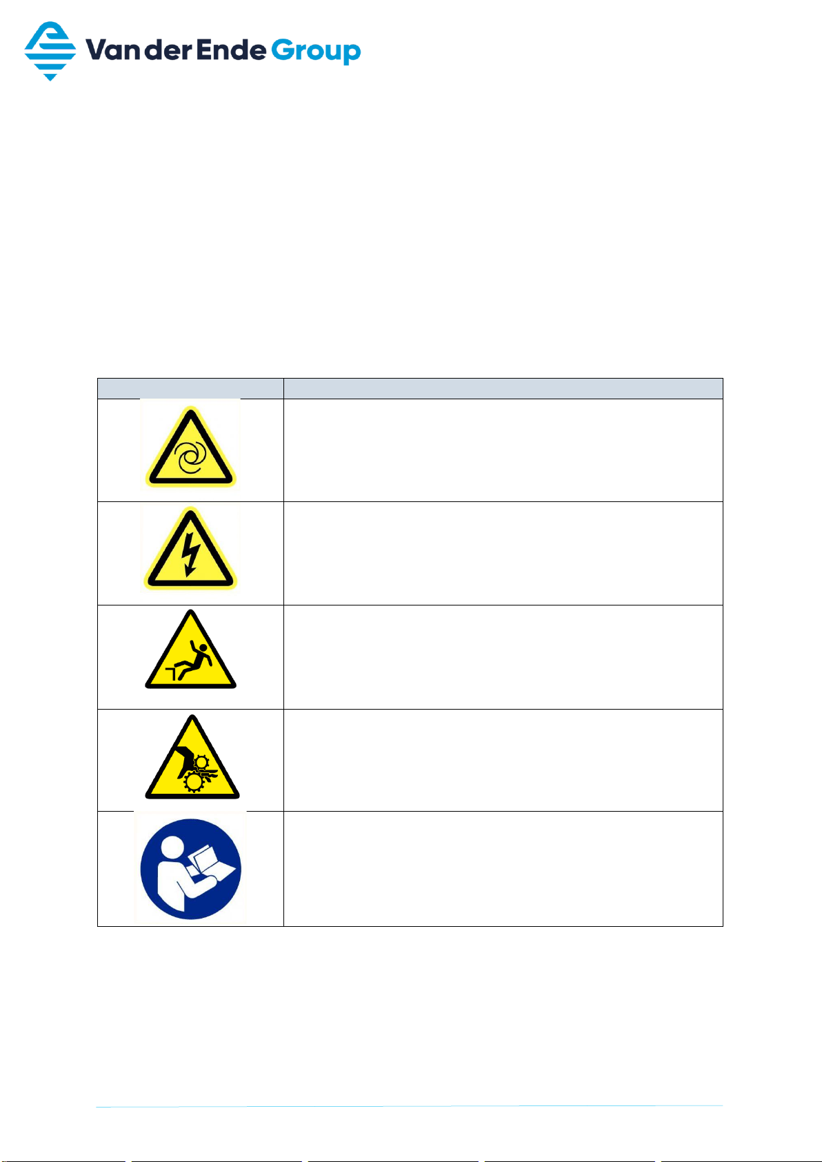
3Safety instructions............................................................................................................................ 8
4Installation ........................................................................................................................................ 9
4.1 Contents of basic installation package.................................................................................... 9
4.2 Method using lowered brackets............................................................................................. 10
4.2.1 Contents of lowered installation package.......................................................................... 10
4.2.2 Mounting of brackets to fan ............................................................................................... 10
4.2.3 Mounting bracket to truss .................................................................................................. 10
4.3 Method with the aid of a steel cable...................................................................................... 12
4.3.1 Content of cable installation kit.......................................................................................... 12
4.3.2 Cable installation ............................................................................................................... 12
4.4 Installation of hose................................................................................................................. 15
5Commissioning............................................................................................................................... 16
5.1 Operating on basis of supply voltage .................................................................................... 16
5.2 Operating on 0-10V external setting signal ........................................................................... 17
5.3 Prerequisites for commissioning............................................................................................ 17
6Operation........................................................................................................................................ 18
7Maintenance................................................................................................................................... 18
8Failures and repairs........................................................................................................................ 19
9Disassembly................................................................................................................................... 20
10 CE Declaration of Conformity.................................................................................................... 21
11 UKCA Declaration of Conformity............................................................................................... 22
Attachments........................................................................................................................................... 23
CE declaration concerning fan........................................................................................................... 24
UKCA declaration concerning fan...................................................................................................... 25

Page 4 of 28
1 IDENTIFICATION
This overview contains general information about the installation. The purpose of this part is to
indicate the demarcation, overall operation and scope of the installation.
1.1 General
1.1.1 Description of the system
The Verti-Fan is a horizontal fan connected to a plastic hose. A stainless steel ring or oval can be
optionally attached to the end of this hose. The Verti-Fan is optionally fitted with a power cord and
plug.
The Verti-Fan has no operating controls.
1.1.2 Specifications
General
Type
Verti-Fan FG035 EC fan
Size of fan
468 x 468 x 125 mm
Max. fan speed
1710 rpm
Capacity
3600 m3/h*
Max. ambient temperature
50 °C
Isolation class
IP54
Total weight
± 5 kg
Connections
Power
160 W
Voltage
~1, 200 -240 V, 50 Hz / 60 Hz
Current
1.35 –1.65 A
Table 1 Specifications
* The capacity depends on the length of the hose.

Page 5 of 28
1.1.3 Diagram of the system
In the figure below, a schematic diagram of the Verti-Fan system with the main components.
Figure 1 Diagram of the Verti-Fan showing the main components and their names
Nr.
Part name
1
Mounting brackets (optionally replacable with cable mounting)
2
Fan
3
Mounting ring
4
Mounting brackets and spacers
5
Stainless steel hose clamp
6
Plastic hose
7
Stainless steel ring or oval including retaining clips (optionally)

Page 6 of 28
1.2 Users
In principle, the Verti-Fan is not controlled directly, but by a user/operator via a control cabinet. These
users/operators must be at least 18 years old, employed by the company where the Verti-Fan is
installed, and designated by the management as competent and authorized to operate the Verti-Fan.
Unintentional users are any users who do not meet the above definition. Unintentional users are all
users who, by using the Verti-Fan, create unsafe situations or danger to themselves or others.
1.3 Use
The Verti-Fan is designed for vertical air circulation in greenhouses, to improve the homogeneity of
temperatures at different heights.
The Verti-Fan is not intended to be used for any other purposes than that described above, and is not
designed for the transport of gases other than air within a temperature range of -10 °C to + 50 °C.
1.4 Authorized servicers
The Verti-Fan may be serviced by any maintenance company, but Van der Ende Group is preferred
because of this company’s thorough knowledge of the Verti-Fan.
Periodic servicing can help avoid unnecessary costs or failures, and improve reliability.
1.5 Operating environment
The Verti-Fan should be installed on the lowest beam of the truss in the greenhouse. There must be at
least 300 mm clearance on the suction side of the fan. If a shade screen is used, this means that the
fan has to be installed lower than the lowest truss, and the mounting brackets adapted. It must not be
possible to touch the ventilator without special equipment, and the beam must be in good enough
condition to bear the weight of the fan.
The Verti-Fan is not intended to be used in any environment other than that described above. The
Verti-Fan is not suitable for use in explosive environments.
1.6 Guarantee conditions
The warranty period is 6 months after commissioning.
If a claim is made under guarantee, the parts concerned must be presented to the manufacturer for
assessment.
The guarantee shall be invalidated in the event of any of the following;
•Improper use
•Repeatedly ignoring advice of the manufacturer or supplier
•Repair, maintenance or use by unauthorized persons
•Use of inappropriate power supply connections
•Use of the machine in an unsuitable environment
•Intentional damage or modification of the machine
1.7 Relevant directives
The Verti-Fan complies with the following directives;
•Machinery Directive 2006/42/EC
•Low Voltage Directive 2006/95/EC
•EMC Directive 2004/108/EC
•Supply of Machinery (Safety) Regulations 2008:1597
•Electrical Equipment (Safety) Regulations 2016:1101
•Electro Magnetic Compatibility Regulations 2016:1091
In accordance with the Low Voltage Directive, the Verti-Fan is classified as a Class I device.

Page 7 of 28
2 DESCRIPTION
2.1 General
The purpose and function of the Verti-Fan is to displace air vertically from above to below in modern
greenhouses. Such displacements of air are often missing in modern, high greenhouses, with
consequent variations in temperature at different heights. Displacing air from above to below has a
favorable effect on growth, maturation and reduces the susceptibility to fungal diseases.
The operation of the Verti-Fan is simple: a horizontally placed fan draws air in at the top of the
greenhouse, and blows it down through a plastic hose. The plastic hose is kept open at the bottom by
a stainless steel ring or oval, and hangs 400 mm above the ground. The Verti-Fan therefore requires
mounting to the beam at the top of the greenhouse with the included bracket or suspension cable.
The Verti-Fan can be used in the cultivation of all sorts of vegetable, fruit and ornamental crops.
2.2 Transportation and Storage
The Verti-Fan is delivered in parts; in other words, the various components are supplied in separate
packages and assembled on site.

Page 8 of 28
3 SAFETY INSTRUCTIONS
When working on the Verti-Fan, always make sure the plug is disconnected from the power supply!
This prevents the fan starting unexpectedly or unintentionally.
The Verti-Fan may never be connected to the power without the mounting ring and plastic hose. This
prevents a danger of cutting parts of the open fan blades.
When mounting the Verti-Fan, make sure that only self-locking nuts are used, otherwise there is a
danger that parts may vibrate loose and fall off.
Mind the fact that it takes a couple of seconds for the fan to start working when it has been turned on.
In compliance with EN ISO 13857, a protective construction has been fitted to the fan to prevent direct
contact. The protective construction consists of the plastic hose, the mounting ring and the hose
clamp. It is for this reason, that the Verti-Fan is not allowed to be operated without these components
being attached to the fan.
Safety symbol
Description
Automatic starting machine!
Electric power present!
Danger of falling!
Rotating parts!
Reading instructions obligated!

Page 9 of 28
4 INSTALLATION
This chapter describes the installation of the Verti-Fan, namely assembling individual parts into a
single unit, ready to be installed.
There are two distinct ways of installing the Verti-Fan:
-Mounting brackets
-steel cable.
For more information on the brackets refer to 4.2, for the steel cable see 4.3.
4.1 Contents of basic installation package
The content of the basic installation package is everything what will be delivered for one Verti-Fan
regardless the type of mounting. In the table below is described what the basic installation contains.
The numbers behind the description are referring to Figure 1 on page 5.
Table 2 Contents of the installation package
Figure 2 Mounting ring Verti-Fan with lowered installation (left) and cable installation (right)
Quantity
Description
Type
1
Fan (2)
axial fan FG035-ZIL
4
Mounting bracket + spacer (4)
connection of mounting ring to fan
1
Mounting ring click system for rapid
attachment of plastic hose to fan (3)
plastic ring (white coated)
1
Hose clamp for mounting plastic hose to
mounting ring (5)
stainless steel hose clamp 50-370 mm
1
Plastic hose (6)
LDPE tube Ø 380 mm
Anti-crack UV-resistant
Optional
1
Stainless steel ring/oval (7)
304 stainless steel 2 mm thick, 35 mm high
ring Ø 385 mm
oval Ø 470x280 mm
3
Retaining clip for mounting plastic hose with
stainless steel ring on the underside (7)
caddy chain tension clamp 3 –8 mm

Page 10 of 28
4.2 Method using lowered brackets
4.2.1 Contents of lowered installation package
In the table below and in the installation description is referred to parts in Figure 3.
Table 3 Contents of lowered installation package
4.2.2 Mounting of brackets to fan
•Attach the two stainless steel lowering brackets (H) and mounting brackets and spacers (B);
oUsing four stainless steel M6 x 20 bolts (I), eight stainless steel M8 bodywork washers
(J) four and stainless steel M6 nuts (K) on the suction side of the fan (A);
▪See Figure 3.
•Make sure that the power cord is on the correct side.
4.2.3 Mounting bracket to truss
•Choose a suitable location;
oFollow, if possible, the drawings supplied by the installer or manufacturer;
oMake sure the hose hangs down vertically;
oMake sure that no objects can fall/hang through the grid on the suction side;
oMake sure that people cannot touch the fan without aids (such as a stepladder);
oCheck that the truss is in good condition;
oCheck for an electrical connection which is sufficiently close.
•Before the fan can be attached to the trellis, the lowered- and mounting brackets and spacer must
be fixed to the fan. This has to be done as prescribed in chapter 4.2.2 and figure 3.
•Make sure you have the proper tools and equipment;
•Make sure the Verti-Fan can be installed safely, get somebody to help if necessary;
•Loosen the U-clamps (L), keep the washers and nuts;
•Mount the Verti-Fan on the lowest beam of the truss in the greenhouse.
•Place the U-clamps (L) over the truss, and through the holes in the lowered brackets;
•Put the washers (M) in place, and tighten the two self-locking nuts (N) hand tight;
•Tighten the self-locking nuts (N) until the Verti-Fan is in a firm horizontal position;
Quantity
Description
Type
1
Basis installation package
See 4.1
2
Lowered bracket
4 mm lowering brackets (H)
40x300x40 mm
1
Mounting of brackets to fan
4x stainless steel hex bolts M6x20 (I)
8x stainless steel bodywork washer M6 (J)
4x stainless nut M6 (K)
1
Mounting of brackets to the trellis
2x U-clamp M8 U50x50 or U60x55 (L)
4x underlay washer M8 (M)
4x hexagonal self-locking nut M8 (N)

Page 11 of 28
Figure 3 Lowered installation of the Verti-Fan using lowered brackets
1x Plastic hose (E)
1x Hose clamp (D)
1x Mounting ring (C)
4x stainless steel
mounting bracket
with spacer (B)
4x Stainless steel
hex bolt m6x20 (I)
4x stainless
steel washer m6
(J)
4x stainless steel
washer m6 (J)
(2)
4x stainless steel
self-locking nut m6
(K)
4x Stainless steel
Washer m8 (M)
4x hexagonal self-
locking nut m8 (N)
2x stainless steel
mounting bracket (H)
2x U-clamp M8 (L)
m8 (L)

Page 12 of 28
4.3 Method with the aid of a steel cable
4.3.1 Content of cable installation kit
In the table below and in the installation description is referred to parts in Figure 4.
Table 4 Contents of cable installation kit
4.3.2 Cable installation
•Choose a suitable location;
oIf possible, follow the included drawings of the installer or manufacturer;
oMake sure the hose (E) is able to hang down vertically;
oEnsure that no objects can fall/hang through the grid on the suction side of the fan (A);
oMake sure that the distance between the fan (A) and any overhead obstacles (e.g.
shade screen) is at least 300 mm;
oIt must not be possible to touch the ventilator without special equipment, such as a
stepladder.
oCheck that the truss is in good condition;
oCheck if there is a socket sufficiently close by;
•Before the fan can be attached to the truss, the 4 mounting brackets and spacers (B) need to be
attached to the fan (A);
oFixate two of the mounting brackets and spacers (B) by means of 2x eye bolt M6 (N),
4x bodywork washer M6 (P) and 4x hexagonal nut M6 (Q). (see figure 5: right side);
oFixate two of the mounting brackets and spacers (B) by means of 2x bolt M6x20 (O),
4x bodywork washer M6 (P) and 2x hexagonal nut M6 (Q). (see figure 5: left side);
•Use proper tools and equipment;
•Make sure the Verti-Fan can be installed safely, if necessary get help from others;
•What you will need:
oSteel cable (R);
o2x wire clamp (S);
o2x shrink sleeve (T);
•Cut the cable (R) to size if necessary, and place some shrink tubing over the ends. Then use heat
to shrink them around the cable ends with the help of e.g. a lighter;
•Loop the steel cable (R) around or through the truss, and secure with a wire clamp (S). Do this
according to detail view D figure 6;
•Hang the Verti-Fan to the steel cable (R) such that it hangs on the eye bolts (N) (see figure 4).
•The positioning of the Verti-Fan is flexible; it can be moved freely along the length of the steel
cable as desired.
•Finally secure the fan with two wire clamps (B) to hold it in position (see figure 4 t/m 6)
Quantity
Description
Type
1
Basic package
See 4.1
1
Mounting of fan
2x eye bolt M6 x 80 (N)
2x bolt M6x20 (O)
8x bodywork washer M6 (P)
6x hexagonal nut M6 (Q)
1
Mounting to truss beam
8 m stainless steel 3 mm cable (R)
4x wire clamp 3/16” M4 (S)
Piece of 3.2 mm shrink tubing (T)

Page 13 of 28
Figure 4 Verti-Fan suspended with aid of a steel cable
Figure 5 Installing the mounting brackets + spacers to the fan by means of
bolts (left) and eye bolts (right)
2x eye bolt M6 x 80 (N)
8x Fender
washer M6 (P)
4x wire clamp (S)
4x hexagonal
nut M6 (Q)
cable (R)
1x hose clamp
(D)
1x mounting
ring (C)
1x plastic hose
(E)
4x mounting bracket
+ spacer (B)
2x hexagonal nut M6 (Q)
1x fan (A)
2x bolt M6x20
(O)

Page 14 of 28
Figure 6 Schematic drawing of a Verti-Fan suspended with the aid of a steel cable

Page 15 of 28
4.4 Installation of hose
The Verti-Fan is installed as follows; use Figure 7:
•Cut the plastic hose (E) to size; the ideal height of the hose from the ground is about 400 mm
(When the option: the stainless steel ring (F) is used, the hose (E) needs to be cut 250 mm);
•When using stainless steel ring (F):
oSlide the ring (F) over the hose (E);
oFold 250 mm of the hose over the ring:
oFit the three retaining clips (G), so that the stainless steel ring (F) is secured to the
hose (E);
oPlace the mounting strip of the retainer (G) facing towards the inside of the hose;
•Slide the other end of the hose over the underside of the mounting ring (I):
•Place the hose clamp (D) around the mounting ring (C) and hose (E), and tighten;
•The mounting ring (C) can now be clicked around the wind tunnel of the fan (A) by placing it over
the spacers which are attached to the mounting brackets (B);
•Insert the plug into the power supply socket;
•Bear in mind at this stage that the Verti-Fan must be visible from the connection point (the socket).
Figure 7 Mounting the plastic hose
1x plastic hose (E)
4x mounting brackets
+ spacer (B)
1x mounting ring (C)
1x stainless steel hose
clamp (D)
1x stainless steel ring/oval (F)
(optional)
3x retaining clip (G) (optional)
1x fan (A)

Page 16 of 28
5 COMMISSIONING
This chapter describes the different electrical wirings that can be used to operate the FG035 fan. The
chosen connection determines the functionality of the Verti-Fan.
Annex B depicts a more comprehensive wiring scheme of the FG035 fan, including the connection
diagram for the 0-10 V control option.
5.1 Operating on basis of supply voltage
The FG035 is delivered with an extra cable. When this cable is connected (as shown by the red line in
Figure 8) in between the E1 socket and 10V socket, the fan will be turned off/on when it receives a
supply voltage. This cable needs to be connected before installation by the installer.
Connect the line voltage to: PE, L1, and N. Here, it must be strictly observed that the line voltage lies
within the allowable tolerance specifications (see technical data).
Figure 8 Wiring scheme FG035 fan
Proceed as follows:
•Remove terminal box cover;
•Insert and connect cables properly and ensure tightness of the cable glands;
•Connect the supplied cable between the E1 and 10 V sockets (see figure 8);
•Close the lid again carefully before start-up (tightening torque for lid screws 1.7 Nm);
Screw terminals
•Nominal torque: 0,8 Nm
•
Stripping length: 7 mm +/-0,5mm
•Clamping range
origid: 0,75…6mm2
oflexiblel: 0,75…4mm2
o18...12AWG

Page 17 of 28
5.2 Operating on 0-10V external setting signal
When the cable between 10V and E1 has not been connected, the fan needs to be controlled through
an external setting signal (0-10V).
Figure 9 depicts the characteristic curve of the fan’s motor torque to the specifications of the external
setting signal.
Figure 9 FG035 motor characteristic curve (0 - 10 V setting signal)
5.3 Prerequisites for commissioning
Before first-time start-up of the Verti-Fan, check the following:
•Has any leftover installation material and other foreign material been removed from the fan
area?
•Are the plastic hose, mounting ring and hose clamp correctly mounted to the fan, safety
devices according to (EN ISO 13857)?
•Check the rotat. direction (see the rotat. direction arrow on the fan blade, impeller base plate
or intake-side support plate).
•Check for quiet, low vibration operation. Strong vibrations due to erratic operation
(unbalanced), e.g. caused by transportation damage or improper use, can lead to failure.
For more information concerning the fan consult the FG035 user manual

Page 18 of 28
6 OPERATION
Operating the Verti-Fan is simple: if it is connected to the power supply it will start working, when it is
disconnected it will stop working. It is possible to set the speed by adjusting the voltage at the plug
with something like a control transformer, but this is not part of the Verti-Fan.
7 MAINTENANCE
When servicing the Verti-Fan, the plug must be removed from the socket, to prevent unexpected and
unwanted starting.
The advice is to do maintenance periodical (± half a year) to the Verti-Fan:
•Keep the top side (suction side) of the fan free of foreign objects and dirt.
•If the air intake grille is dirty, clean it with a dry brush and then wipe down with a damp cloth.
•If the fan blades or fan housing are dirty, wipe down with a damp cloth.
•Replace the capacitor after 10,000 operating hours. This will help maintain the correct speed
and avoid excessive power consumption.
•Check if the wire clamps are still tight in the case of cable mounting.
Other maintenance that must be taken into account at all times:
•Replace the plastic hose when damaged or soiled;
•If the device is not in use for longer periods in a humid atmosphere, it is recommended to
operate the motor/fan for at least two hours every month at 80 - 100 % of maximum speed to
remove any moisture that has penetrated inside.
•Check if all the bolt and nuts with which the fan is mounted are still tight. This prevents the
danger of unexpected falling objects.

Page 19 of 28
8 FAILURES AND REPAIRS
Failure
Possible cause
Solution
Fan does not
run (anymore)
No mains voltage
Failure of a phase
Under- over over voltage
Check line voltage
Ground fault
Check motor connection and line voltage
Short circuit winding
Replace fan
Motor thermal protection has
tripped (motor overheated)
−Check free airways, if necessary.
remove foreign bodies
−Check supply air temperature
−Check voltage
Impeller is blocked or dirty
−Disconnect the motor from the power
supply and secure it against being
switched on again
−Check the voltage is disconnected
−Remove the protective grille
−Remove foreign bodies or dirt
−Refit the protective grille
−Further procedure as in chapter
"Commissioning"
Fan won’t start
Temperature too low for bearing
grease
Use bearing with cold grease
Airflow in wrong direction (motor
reverses at high speed)
Check airflow
(see airflow reverse rotation behavior)
See ‘Fan does not run’
Fan runs to
slow
Impeller / wing rubs
remove foreign objects / dirt in the fan
Active temperature management is
activated
(motor or electronics overheated)
Check whether the airways are free, if
necessary. remove foreign objects
See 'Impeller is blocked or dirty'
Check the temperature of the supply air
Check the installation space (air velocity over
the cooling elements)
Air flow to low
Fan runs too slowly
See ‘Fan runs to slow’
Airways blocked
Check whether airways are free (air supply /
exhaust valves, filters)
See 'Impeller is blocked or contaminated'
Pressure loss different than
projected
Check fan selection
Vibrations
unbalance
Check wings / shovels for damage,
contamination or icing
See "Impeller is blocked or contaminated"
No or wrong vibration dampers
(only with radial)
Fit correct vibration dampers
Unusual sound
Bearing damaged / worn
Replace bearing
For motor size 055 (“z” / “b” with cross flow) and
072 (o) replace fans
Impeller / wing rubs
Remove foreign objects / dirt in the fan
See 'Impeller is blocked or dirty'
Operation over the tear-off point
(for axial fans)
Check that airways are clear (air supply/exhaust
valves, filters)
Incorrect cover on nozzle (with
radial fans)
Observe assembly instructions

Page 20 of 28
9 DISASSEMBLY
Make sure the plug is disconnected to prevents unintended and unwanted starting of the fan. Make
sure the workplace is safe, then remove the self-locking nuts of the U-clamps, or if using cables
unhook the Verti-Fan from the cables. The Verti-Fan can now be removed.
This manual suits for next models
1
Table of contents
Other VAN DER ENDE Fan manuals
Popular Fan manuals by other brands

Wind River Spas
Wind River Spas Novato WR1466 Series Installation

EQUATION
EQUATION FT-1205RDCII Legal and Safety Instructions

Harbor Breeze
Harbor Breeze CANTLEY 41557 manual

Nibe
Nibe GV-HR 130 Installer manual

NORDICCO
NORDICCO AIR MINI installation manual

Bryant
Bryant ERVBBLHA Series installation instructions