Vanair Goodall START-ALL Hydraulic Series User manual

START•ALL®
Hydraulic Series Troubleshooting Guide
Start•All Hydraulic Series
Troubleshooting Guide
Rev 11122019

2 VANAIR.COM • 800-526-8817 START•ALL®HYDRAULIC SERIES TROUBLESHOOTING GUIDE
SAFETY PRECAUTIONS & INSTRUCTIONS ....................................... 3-4
GENERAL INSPECTION .......................................................................... 5
GENERATOR TEST.................................................................................. 5
TESTING THE SOLENOIDS..................................................................... 6
TESTING THE VOLTAGE CONTROL....................................................... 6
FIXING REVERSE POLARITY GENERATORS........................................ 7
12/24 VOLT RED LABEL VOLTAGE CONTROL TEST............................. 8
RED LABEL ENERGIZE BUTTON TEST.................................................. 8
MAINTENANCE LOG................................................................................ 9
CONTACT INFORMATION...................................................................... 10
TABLE OF CONTENTS

3
VANAIR.COM • 800-526-881 START•ALL®HYDRAULIC SERIES TROUBLESHOOTING GUIDE
SAFETY PRECAUTIONS AND INSTRUCTIONS
SIGNAL WORDS
Safety messages are provided throughout this manual to help
prevent personal injury and equipment damage. All safety
messages are introduced by a signal word indicating the hazard
level.
This symbol, in combination with other safety
and control symbols, points out important safety
information that, if not followed, could endanger
personal safety and/or damage to property.
!
Indicates an imminently hazardous
situation which, if not avoided, will result in
death or serious injury to the operator or
bystanders.
DANGER
!
Indicates a potentially hazardous situation
which, if not avoided, could result in
death or serious injury to the operator or
bystanders.
WARNING
!
Indicates a potentially hazardous situation
which, if not avoided, may result in
moderate or minor injury to the operator or
bystanders.
CAUTION
!
Indicates a situation which, if not
avoided, may result in damage to the unit
components.
NOTICE
!
WARNING
!
WARNING
ACCIDENTAL STARTING
Accidental starting can cause
severe injury or death.
!
WARNING
SULFURIC ACID
IN BATTERIES
Wear protective goggles and clothing.
Battery acid may cause blindness and
burn skin.
!
WARNING
Engine exhaust from this product
contains chemicals known to
the State of California to cause
cancer, birth defects, or other
reproductive harm.
!
CARBON MONOXIDE
The exhaust system must
be leakproof and routinely
inspected.
Can cause severe nausea,
fainting, or death.
Can cause severe injury or death.

4 VANAIR.COM • 800-526-8817 START•ALL®HYDRAULIC SERIES TROUBLESHOOTING GUIDE
SAFETY PRECAUTIONS AND INSTRUCTIONS
WARNING
!!
DANGER
! !
POISON
!!
CAUTION
! !
WARNING
! !
Read And Adhere To All Safety Warnings Before Operating Any Mechanical
Equipment.
Explosive gases are produced during the boosting and charging process. The smallest spark can
ignite these explosive gases. To avoid battery explosion and serious personal injury, follow these
important safety precautions when boosting a battery:
•Always wear safety equipment such as goggles, gloves, ear plugs, and head protection at all
times when operating the unit.
•Keep ames, cigarettes, and other ignition sources away from the battery.
• Avoid contact with metal objects such as tools and jewelry that could cause sparks.
• Never lean over the battery during charging, testing, or boosting.
•Check the battery for low water level or frozen conditions. NEVER BOOST A FROZEN BATTERY;
rupture or explosion could occur, causing serious personal injury.
•Vehicle owner’s manual may indicate further precautions which also should be followed when
attempting to boost a vehicle.
Battery Acid Causes Severe Burns. Avoid Contact With Skin, Eyes, Or
Clothing.
When unit is not in use, keep all switches and fuel valve turned OFF.
•Always keep cable clamps separate so they do not come in contact with each other. The clamps
could short circuit, creating arcing or sparking, which may cause damage.
•Periodically inspect cables for cracking or abrasion; this may cause the copper to become
exposed, which could cause sparking or arcing during operation.
The mufer becomes very hot during operation and remains hot for a while after stopping
the engine.
• Never touch hot surfaces and avoid hot gases.
• Let engine cool before storing unit.
NOTE:
Since there are many variations in the circumstances surrounding the
installation, operation, and maintenance of this unit, we cannot possibly
anticipate or provide advice or safety messages to cover every situation.

5
VANAIR.COM • 800-526-881 START•ALL®HYDRAULIC SERIES TROUBLESHOOTING GUIDE
TOOLS REQUIRED FOR THE JOB
Digital Volt Ohm Meter/Multi Meter
(2) Jumper Wires that are 6-12” long, 14 gauge or better wire, with clamps at both ends
12 volt battery or jump pack that is in good working order
Set of jumper cables (if using a 12 volt battery for testing)
GENERAL INSPECTION
• Inspect the cable/clamp assembly; look for cuts, abrasions, or breaks in the cable.
• Check for worn jaws on clamp ends.
• Check for excessive corrosion on all terminal end connections.
•Check for proper belt tension. Belts should deect approximately 3/8” under light nger pressure
PLEASE NOTE: THIS TROUBLESHOOTING GUIDE HAS BEEN DESIGNED TO TEST YOUR START•ALL®
UNIT IN THE ORDER WRITTEN. IT IS NECESSARY TO FOLLOW THE TROUBLESHOOTING STEPS
IN ORDER FROM BEGINNING TO END. FAILURE TO DO SO WILL RESULT IN FALSE READINGS AND
MAY CAUSE DELAYS IN THE TROUBLESHOOTING PROCESS.
For Proper Testing Procedure And To Ensure Proper Output Of The Generators, Please
Do The Test With The Generators On The Machine (Not Being Bench Tested).
NOTICE
!
TESTING THE GENERATORS
1. Inspect the generator for a solder ring, solder akes or drops inside the generator housing just behind the brushes. If a
ring of solder is found near the brush plate, the generator needs to be replaced; the generators have been overheated.
If no solder ring is found, each generator needs to be tested.
When testing the 79-406/79-510 isolated ground generator, the ground stud on the
bottom of the generator must be grounded by running a jumper wire from the
ground stud to a good ground connection (such as a generator mounting bolt). You
will also need to jump the eld post and the armature post together. These isolated
ground generators are only used on 12/24 volt single cable starting units. (Fig. 1)
2. Remove all the wires from the generators and label them for re-installation. Install a bypass lead between the eld post
(small terminal on top of the generator) and armature post (large terminal on top of the generator). (FIG. 2)
3. Attach the positive probe from a volt meter to the armature post, and the negative probe to a good ground connection
(such as a generator mounting bolt).
4. With the ow control at maximum, the voltage should read 22-28 VOLTS on the volt meter. If the voltage reads 22, check
the brushes for excessive wear. Brush length should be a minimum of 1/4”. If brushes are less than 1/4”, replace the
brushes. Retest generator to conrm 22-28 Volts until all generators pass the test.
5. If little or no voltage is present, replace or rebuild the generator.
6. Test the remaining generators by following the above steps for each generator. If all generators perform satisfactorily,
reconnect the wires to each of the generators. DO NOT HOOK UP THE VOLTAGE CONTROL WIRES AT THIS TIME.
NOTICE
!
FIG. 2
FIELD POST ARMATURE POST
FIG. 1
FIELD POST
GROUND
GROUND POST ARMATURE POST

6 VANAIR.COM • 800-526-8817 START•ALL®HYDRAULIC SERIES TROUBLESHOOTING GUIDE
TESTING THE SOLENOID(S) 860-224
1. Remove all the wires from each solenoid, and label for re-installation. Failure to do so could result in permanent
damage to the voltage control.
2. Apply 12 volt negative to one small stud and 12 volt positive to the other small stud on each solenoid. The solenoid
should engage, and you will hear the contact closing. With power still applied to the small terminals on the solenoid,
measure the resistance between the larger terminals. The reading should be near zero ohms. If the solenoids do not
engage, or if the reading between the large terminals is high, the solenoid should be replaced. (FIG. 3)
3. It is also possible to have a shorted solenoid. With no power applied to the solenoid, measure the resistance between
the large terminals. The reading should be open; if the reading is near zero ohms, replace the solenoid. (FIG. 4)
4. Do not install the voltage control wires on solenoids until voltage control module has been tested. Install all other wires
to correct location on the solenoids, and proceed to test the voltage control.
FIG. 3 FIG. 4
TESTING THE 850-597 VOLTAGE CONTROL
IF YOUR UNIT HAS THE TWO WIRE 70-600-K VOLTAGE CONTROL, YOU WILL NEED
TO CALL VANAIR®MFG AT 844-526-8817 FOR AN UPGRADE KIT.
1. Conrm the fuse on the orange wire is not open. If open, replace with a 30 amp fuse (FIG. 5). If the fuse is not open,
proceed to the next step.
2. Disconnect all wires coming from the voltage control. Disconnect the connector on the orange wire. (FIG. 6)
3. Place a jumper wire across the eld and armature terminals on any generator. The eld terminal is smaller and has
green wires attached. The armature terminal is larger and has heavy gauge wires attached. (FIG. 7)
4. Place a jumper wire between the small solenoid terminal containing the brown wire and a ground on the START•ALL®
(such as a generator mounting bolt).
5. Place a jumper wire between the switch side connector on the orange wire and the eld post on any one of the
generators. (FIG. 8)
6. Connect a digital voltmeter to the battery clamps and set to DC voltage scale.
7. Make sure the boosting switch is in the “OFF” position. Start and run the unit at 3/4 throttle.
8. Move the switch to the 12V position (FIG. 9) and increase ow control to maximum ow.
9. You should see raw voltage of 28V or higher.
ILLUSTRATIONS ON NEXT PAGE
TROUBLESHOOTING FOR START•ALL®UNIT
USING THE START•ALL®FOR BOOSTING WITH THE VOLTAGE CONTROL
BYPASSED SHOULD BE AVOIDED, DUE TO THE POSSIBILITY OF
EXCESSIVE VOLTAGE BEING CREATED.
NOTICE
!

7
VANAIR.COM • 800-526-881 START•ALL®HYDRAULIC SERIES TROUBLESHOOTING GUIDE
FIXING REVERSE POLARITY GENERATORS (ONLY USED IF REVERSE POLARITY IS SUSPECTED)
If your unit is continually blowing the 30 amp fuse in the voltage control line, you could have reversed/negative polarity
generator. To x this, you must have either a 12 volt jump pack or a 12 volt battery with jumper cables. Do the procedure on
the far left generator and then repeat the same step on the one right next to it. THE 12 VOLT JUMP PACK OR 12 VOLT
BATTERY HAS TO BE IN GOOD WORKING CONDITION.
WHEN USING A 12 VOLT BATTERY (WILL ALSO REQUIRE A SET OF JUMPER CABLES)
1. Hook the jumper cables up to the battery with the black clamp on the negative post and the red clamp on the positive
post. DO NOT LET THE OTHER ENDS TOUCH, OR THERE WILL BE SEVERE SPARKING THAT COULD CAUSE
DAMAGE.
2. With the other end of the cables, take the negative black clamp and put it on a good ground on the unit.
3. Scratch the positive red clamp across the eld post of the generator, which is the smaller of the two posts on top of the
generator. It is normal to see sparks while doing this. Do not attach the positive cable clamp; you must scratch it across
the eld post.
4. Once you have done this a few times, you will have reversed the polarity back to positive in all of the generators, as long
as the wires have been hooked back up correctly.
FIG. 8
JUMPER TO FRAME
GROUND OR A
KNOWN GROUND
FRAME GROUND JUMPER TO FIELD POST
FIG. 9
SWITCH
TROUBLESHOOTING FOR START•ALL®UNIT
WHEN USING A 12 VOLT JUMP PACK
1. Put the negative clamp to a good ground on the unit.
2. Turn the jump pack on while holding onto the positive cable. Scratch it across the eld post on the generator, which is
the smaller of the two posts on top of the generator. It is normal to see sparks while doing this. Do not attach the positive
cable clamp to the eld post as this may cause damage to the generator. You must scratch it across the eld post.
3. Once you have done this a few times, you will have reversed the polarity back to positive in all of the generators, as long
as all the wires have been hooked back up correctly.
FIG. 5 FIG. 6 FIG. 7
ARMATURE POST
FIELD
POST
SMALL SOLENOID TERMINAL
CONTAINING THE BROWN WIRE
SWITCH SIDE
CONNECTOR TO
FIELD POST
Start•All®610 pictured

8 VANAIR.COM • 800-526-8817 START•ALL®HYDRAULIC SERIES TROUBLESHOOTING GUIDE
12/24 VOLT RED LABEL VOLTAGE CONTROL SWITCH TESTS
In the “ON” position, the switch connects the Armature output to the orange wire on the regulator and the
appropriate solenoids for the selected voltage. This test is performed with an ohmmeter or continuity tester.
CHECK THE “OFF” POSITION
1. With the switch in the “OFF” position, check for continuity between any combination of the red, orange,
black and purple wires.
2. Is there continuity present?
a. If YES - The switch has an internal short. Replace switch assembly.
b. If NO - This portion of the switch is working correctly. Proceed to ‘Check the “ON” Position for 12V Side’
section.
CHECK THE “ON” POSITION FOR 12V SIDE
1. Move the switch to the “12V” position.
2. Measure for continuity between the red and black wires coming from the switch.
3. Is there continuity between the red and black wires?
a. If YES - This portion of the switch is working correctly. Proceed to the ‘Check Continuity on Orange/Black
Wires (1)’ section.
b. If NO - This portion of the switch is not working correctly. Replace switch assembly.
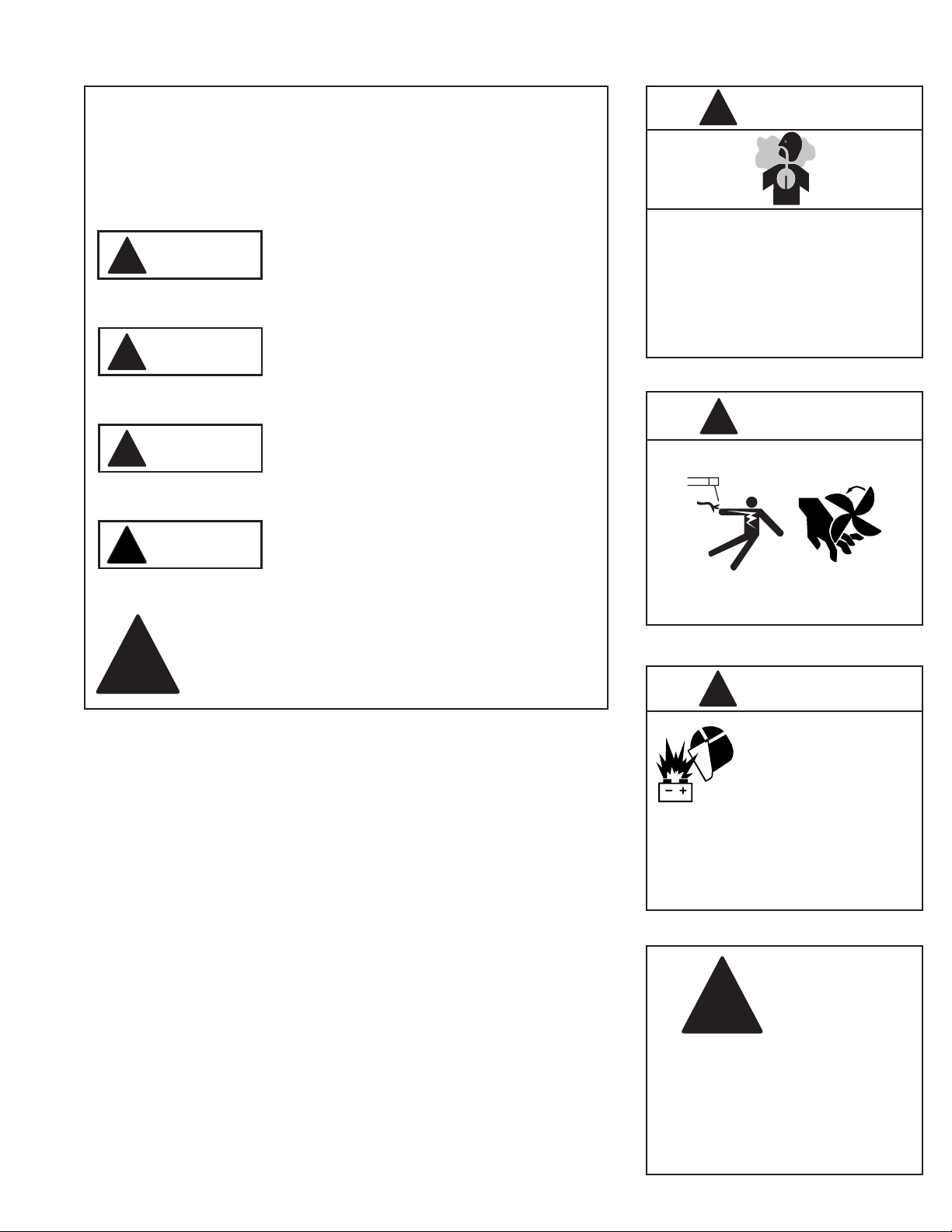
CHECK CONTINUITY ON ORANGE/BLACK WIRES (1)
1. Measure for continuity between the orange and black wires coming from the switch.
2. Is there continuity between orange and black wires?
a. If YES - This portion of the switch is working correctly. Proceed to ‘Check the “ON” Position for 24V Side’
section.
b. If NO - This portion of the switch is not working correctly. Replace switch assembly.
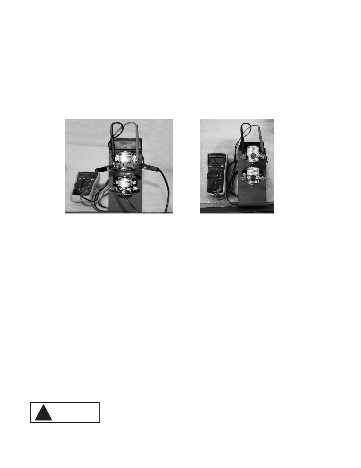
CHECK THE “ON” POSITION FOR 24V SIDE
1. Move the switch to the “24V” side.
2. Measure for continuity between the purple and black wires coming from the switch.
3. Is there continuity between the purple and black wires?
a. If YES - This portion of the switch is working correctly. Proceed to ‘Check Continuity on Orange/Black
Wires (2) section.
b. If NO - This portion of the switch is not working correctly. Replace switch assembly.
CHECK CONTINUITY ON ORANGE/BLACK WIRES (2)
1. Measure for continuity between the orange and black wires coming from the switch.
2. Is there continuity between orange and black wires?
a. If YES - This portion of the switch is working correctly. Proceed to Energize Button Test.
b. If NO - This portion of the switch is not working correctly. Replace switch assembly.
ENERGIZE BUTTON TEST
CHECK THE ENERGIZE BUTTON
1. With the engine key in the “ON” position, use the voltmeter to check the voltage between the wire coming
from the engine battery and the frame ground.
2. Does the voltage measure at least 12V?
a. If YES - Voltage coming from the engine battery is good.
b. If NO - Ensure that engine starting battery is good and fully charged. Repair/replace wire from battery if
necessary.
On 12/24V Start•All®units, there is a red momentary-contact push button switch labeled “ENERGIZE”.
Pressing the energize button connects the engine-starting battery through a resistor and diode to the eld
terminal of each generator. The purpose of this circuit is to feed a small amount of current to the generator
eld coil if the switch is set to either “12V” or “24V” so that the generator output will build up to the point that
the regulator takes over control of the generator eld current.

9
VANAIR.COM • 800-526-881 START•ALL®HYDRAULIC SERIES TROUBLESHOOTING GUIDE
MAINTENANCE LOG

10 VANAIR.COM • 800-526-8817 START•ALL®HYDRAULIC SERIES TROUBLESHOOTING GUIDE
SERIAL NUMBER LOCATIONS
When calling for technical support, it is important to provide the serial number of the Start•All®unit.
The serial number will be a white tag with black type located on the front panel on the Start•All®.
FOR TECHNICAL SERVICE,
PLEASE CONTACT US DIRECTLY AT:
VANAIR MFG
844-826-7378
HAVE THE MODEL NUMBER AND SERIAL
NUMBER AVAILABLE BEFORE CALLING
This manual suits for next models
1
Table of contents
Other Vanair Remote Starter manuals
Popular Remote Starter manuals by other brands

EINHELL
EINHELL BT-PS 1000 Directions for use

NOCO Genius
NOCO Genius Boost HD GB70 user guide

EXTOL PREMIUM
EXTOL PREMIUM 8897320 Translation of the original user manual

Directed Electronics
Directed Electronics VIPER 5901 owner's guide

Code Alarm
Code Alarm ca6154 Professional Series installation guide

Autostart
Autostart AS-1585 SH installation guide