V&T V5 Series User manual

V6−GH/GA V5−GH/GA
High performance special inverter for
inverter
User manual
V5/V6 Series
USER’S MANUAL
V&T

Foreword
ShenZhen V&T Technologies Co.,Ltd. was certificated as a "National
Hi-tech and Double-Software Enterprise" engaged in Variable Frequency Drive,
Servo Drive, Electric Vehicle Controller, Inverter and other power electronics
product with independent intellectual property rights covering
R&D,manufacturing, marketing, with the profound drive know-how, we has won
the technical innovation prize,the most competitive brands prize, Champions of
National Hybrid Electric Vehicle competition and one of Top Ten Variable
Frequency Drive Enterprises in China and etc.
ShenZhen V&T Technologies Co.,Ltd. has advanced asynchronous vector
control technology and torque control technology which is the core control
technologies in motor drive section, Through continuous technological
innovation and international technical
exchange, V&T developed core technology with most experienced R&D
team in China and completed industrial design and production capacity, Has a
rich standard product line, a variety of industry special machine series, voltage
level from 220V to 1140V and power rating from 0.4KW to 3MW; can meet many
kinds of applications.
V&T crane special inverter adopts high performance torque vector control
technology. It has excellent torque control,reliable brake control timing, speed
monitoring, torque monitoring, power optimization, location processing,
intelligent deceleration functions, fully guarantee the safety, efficiency and
reliability. It be widely used in port, ships , marine engineering, mining,
construction, metallurgy,factories and other industries crane machinery.
According to the different characteristics of the lifting industry, V&T has launched
a variety of lifting products to meet different application needs.
The V6-GH inverter is suitable for hoisting mechanisms with encoder
feedback.

The V5−GH inverter is suitable for hoisting mechanisms without encoder
feedback.
The V6−GA inverter is suitable for mechanisms with encoder feedback.
The V5−GA inverter is suitable for mechanisms without encoder feedback.

Profile of high performance crane special inverter
◆ Professional crane function, it is a perfect combination of PLC and
high-performance vector inverter.
Built-in unique crane special functions for V&T crane special inverter are a perfect
combination of crane special PLC and high-performance vector inverter. Its powerful, easy
programming ,wiring and cost-effective.
◆ Powerful starting torque in low frequency
The product adopts precise torque vector control algorithm, vector control without encoder
0.5Hz up to 180% rated torque, the torque response is less than 20ms; vector control with
encoder 0.00Hz up to 180% rated torque, the torque response is less than 10ms. With
reliable brake control logic, to ensure opening and closing of the brake will not appear slip
phenomenon.
◆ Reliable brake control to eliminate the phenomenon of slip hook
Precise torque vector control algorithm combined with a reliable brake control logic, to
ensure opening and closing of the brake will not appear slip phenomenon.
The first thing to start motor is to ensure that the motor has reached a certain frequency, the
output torque was sufficient to open the mechanical brake and after process mechanical
brake delay can normally accelerate to the setting speed; when stop motor, first of all let the
motor as reasonable deceleration gradually decelerate to the brake close speed, and let
the motor still output torque, then closed mechanical brake.Through the above functions
can be better able to prevent the load slip hook at the moment of opening and closing the
brake.
Start command
Motor ru nning
Frequency given
Frequency output
Brake command
Brake status
turn on
sh ut down
turn on
sh ut down
f1 f2
t1 t2
f3
f4
t3
I>Ilift
T>Tlift
f1:Brake opening frequency (forward/reverse)
f2:Brake delay frequency (forward/reverse)
f3:Brake closing frequency (forward/reverse)
f4:Slip delay frequency (forward/reverse)
t1:Delay before the brake is ope ned
t2:Brake open delay
t3:Slip delay time
I:Output current
T:Output torque
Ilift:Brake open current (forward/reverse)
Tlift:Brake opening torque (forward/reverse)
Brake is the most crucial and most important institutions of crane system. Reliability of brake
relates to safety of whole machine. Except the brake control time sequence to ensure reliable

operation of the brake, also need to take full account of safety when brake faults. Inverter
adopted control circuit three class control logic&main circuit two class contactor control for the
aspect hardware of brake control. The three class control logic includes safety protection of
whole machine, security protection of machine structure and control operation of PLC and
inverter main circuit two class contacts are safety contactor and working contactor. Safety
contactors was controlled of interlock by safety protection of whole machine, security protection
of machine structure. Working contactor was controlled by PLC and control logic of inverter. In
normal security contactor keep
normally closed, brake release and engage was controlled by working contactor. In
dangerous situation security protection of the whole machine, security protection of
machine structure works. Safety contactors and working contactor will disconnect at same
time to ensure the closed brake.
Cilcuit breaker Safety contactor Working contactor
M
◆ Smooth and reliable up-and-down speed
Unique speed torque control in process of acceleration and deceleration and perfect
reliable brake time sequence control function to ensure that the process of the up and
down more stable.
◆ Strong overload capacity
Taking the practical condition of crane equipment into account, V6-GH and V5-GH crane
dedicated inverter overload capacity is 1.2 times of universal heavy duty inverter. With the
more powerful overload capacity achieve excellent control effect.
◆ Has power optimization features
The inverter automatically calculates the weight of the load in the process of motor running
and figured out the maximum speed of motor when it carry the load. So that the motor
could running in high speed and working in the safety power. Maximize useful motor power,
ensuring safety while improving working efficiency.
◆ Position processing functionality and intelligence deceleration
function
By speed signal processing of PG feedback, it could automatic work out of the actual
position without additional device.And it could be precisely to the millimeter. Providing data
for position control such as intelligence deceleration, spot parkin, display the data. When
inverter power off, it can memorize the location.
Intelligent deceleration function is according to the user's setting or protection requirement

the system determines the motor deceleration time and speed in the shortest time to safely
and efficiently achieve designated parking to ensure the safety of the drive system and
accurately stop, Accuracy to centimeter.
The unique position protection and hardware limit mutual monitoring to ensure the system
more secure and efficient.
◆International standard bus communication and optimized
communication protocol
With dual 485 communication interface, support international standard Modbus protocol
(RTU), optional ProfiBus - DP expansion card, CanOpen expansion
cards and other communication protocol to meet different application requirements.
Optimized fast communication protocol highly improved the speed of communication.
With communication loop detection function. Once the communication error will
immediately braking to ensure system security.
◆ Security perfect keyboard functions
Using the keyboard on-site to operate inverter can achieve all cranes start, stop, control
time sequence. The main purpose of this feature is when there is any failure for the crane
control system it could operate the keyboard to safely and efficiently put down the load to
minimize the impact for production.
◆ Comprehensive monitoring and fault protection
Except common inverter overcurrent, overload, overvoltage and other 30 kinds of
protection functions. It also has the speed monitoring function, torque monitoring,
communications detection, brake monitoring and other crane special protection. ensure
safe, reliable operation.
With fault situation exit function, once the system organization has problem, when it can
not start using inverter keyboard could exit the fault situation to minimize the impact for
production.

Typical applications crane industry
■ Port tire cranes, portal cranes
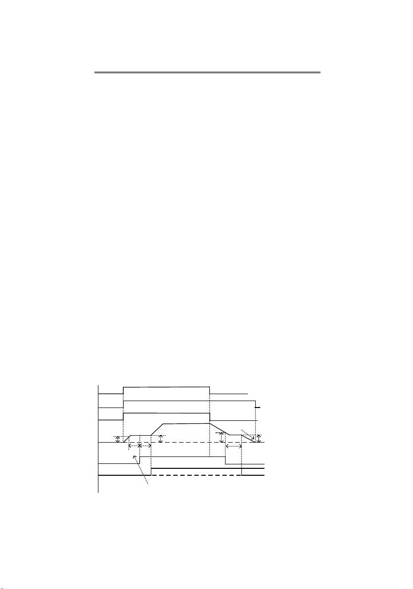
◆ Reliable brake control time sequence to ensure safe and reliable;
◆ Unique torque verification feature ensures the heavy will not have slip phenomenon
when the brake release;
◆ Innovative power optimization and optimization functions ensure that the motor can up to
operation efficiency maximization by safety rated power;
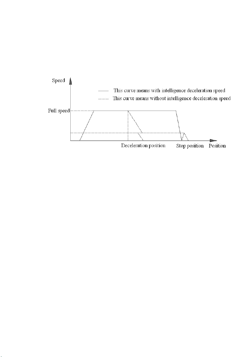
◆ Precise position control and intelligent deceleration function to ensure the system more
secure and reliable, and through intelligent deceleration to prevent upward to the top
phenomenon;
◆ fast response capability ensures easy operation, easy jog to position operation;
◆ Powerful zero speed torque to ensure safety and reliability of the whole system;
◆ Optimized communication format, greatly improving the efficiency and speed of
communication;
◆ Compatible with a variety of communication modes to meet the communication needs of
different systems.
■ Tower cranes/ lifts
◆ Arbitrary acceleration and deceleration and arbitrary impact load conditions, the inverter
runs stable without tripping on the premise of improving energy efficiency;
◆ Strong ability to adapt to the environment, to ensure that the inverter in the wind, rain,
sun, strong vibration and other harsh outdoor environment safe and reliable operation;
◆ Powerful low frequency torque to ensure that does not occur slip phenomenon when
heavy objects is upward;
◆ Excellent control performance ensure that the system is compatible with the open-loop
and closed-loop control;
◆ No need independent fault reset button, intelligent fault reset mode, making the system
easy to operate, more secure and reliable;
◆ optimized lift control logic, making the rise and fall during the startup and shutdown
smoothly without shocks.
■ Electric hoist, overhead crane
◆ Modular electric hoist special inverter, installation easier;
◆ The characteristics of the motor in the tapered, development control software for conical
motor, the inverter perfect integrated with conical motor;
◆ Accurate low speed vector running algorithm to ensure that low-speed region can
achieve sufficient startup ability to prevent slip hook phenomenon;
◆ No need auto tuning normal operation of the performance without affecting, truly
maintenance free debugging features;
◆ High reliability, low cost nature, no need PLC control circuits, simplifying the technical
program, the protection of the product quality and safety of the premise, reduce

customer costs, improve customer competitiveness in the market.
■ Mine hoist, winch
◆ Powerful low frequency torque to eliminate the phenomenon of slip hook;
◆ smooth acceleration and deceleration process greatly reduces the chance of off road;
◆ Easy to use, operating habits unchanged, the operator first operating frequency winch,
still remember it perfectly;
◆ Support and coexistence of the original system, without changing the original system
anything;
◆ Combine perfectly brake with safety circuits to use, the safety circuit of original system
can be compatible , and also match various mechanical brakes perfectly to maximize
the safety protection of the entire system;
◆ maximize efficiency, energy-saving space, in line with national energy conservation
policy;
■ Grab Control
◆ for grabs for precise control, crawl quantity controllable;
◆ opening and closing have been taken to positions control, reduce excessive closed
when closed bucket;
◆ Support and opening and closing rope torque balance, neither spillage nor excessive
force when opening and closing mechanism;
◆ to improve the working efficiency of grab bucket and extend Grab life rope, reduce the
labor intensity of drivers.

Contents
Chapter 1 Introduction of crane series inverter .................................................................... 1
1.1 Product Model Description ............................................................................................. 1
1.2 Product Nameplate Description ...................................................................................... 1
1.3 Product Series ................................................................................................................ 2
1.4 Product Outline, Mounting Dimension, and Weight ........................................................ 4
1.5 Brake resistor selection .................................................................................................. 6
Chapter 2 Installation and Wiring of the Inverte ................................................................... 7
2.1 Product and peripheral device connections and instructions .......................................... 7
2.2 Functions of Main Circuit Terminal.................................................................................. 9
2.3 Control loop wiring ........................................................................................................ 10
2.4 Terminal Wiring diagram ................................................................................................ 11
Chapter 3 Operation Panel Instructions .............................................................................. 12
3.1 Introduction to Operation Panel .................................................................................... 12
3.2 Keyboard parameter change process........................................................................... 13
3.3 Operation Example ....................................................................................................... 14
Chapter 4 Crane special inverter parameters lists ............................................................. 15
Chapter 5 Debugging process ............................................................................................. 29
5.1Confirm the wiring correct connected and firm .............................................................. 29
5.2 Self-learning parameters setting ................................................................................... 29
5.3 With encoder control parameters setting ...................................................................... 30
5.4 Startup parameters setting ........................................................................................... 30
5.5 Speed given mode ........................................................................................................ 30
5.6 Brake control parameters setting .................................................................................. 31
5.7 Conical motor debugging .............................................................................................. 31
5.8 Position control calculation ........................................................................................... 31
5.9 Parameters copy function for batch debugging ............................................................ 32
5.10 Method of operating a inverter without a motor .......................................................... 32
5.11 Parameter monitoring and input terminal status monitoring ........................................ 32
Chapter 6 Crane specialinverter faults and troubleshooting ............................................ 34
6.1 Fault Display ................................................................................................................. 34
6.2Hoisting equipments causes of common failures and analysis ...................................... 38


high performance crane special inverter User Manual
Chapter 1 Introduction of crane series inverter
1.1 Product Model Description
The digits and letters in the inverter model field on the nameplate indicate such information as the
product series,
power supply class, power class and software/hardware versions.
V6
-
GH 4 T 11G
-
AX XX
-
GA
General heavy duty series,
dedicated for translation
mechanism
-
00~99
Hardware non-standard version
A0~Z9
Software non-standard version
11G
11kW heavy load
S
single-phase
T
Three phase
2
4
200V
400V
Super heavy duty series,
special for hoisting
GH
V5
Closed loop torqu e vector
control technology platform
V6
Open loop torque vector control
technology platform
6690V
B1140V
X
A~Z
Structure version
D
DC input
1.2 Product Nameplate Description
MODEL: V6-GH-4T11G
POWER: 11kW
INPUT: AC3PH 380-480V 50/60Hz 33A
OUTPUT: AC3PH 0-480V 0-300Hz 30A
SN:
PASSED
Product model
Power class
Input specification
Output specification
Product barcode
Manufacturer

high performance crane special inverter User Manual
2 Chapter 1 Introduction of crane series inverter
1.3 Product Series
■ V6−GH−4T□□□G□ and V5−GH−4T□□□G□ Three-phase 400V Constant
torque/heavy-duty application
Power(kW) 0.4 0.75 1.5 2.2 3.7 5.5 7.5 11 15 18.5 22 30 37 45 55
Moto
r
power(kW) 0.4 0.75 1.5 2.2 3.7 5.5 7.5 11 15 18.5 22 30 37 45 55
Output
Voltage (V) Three-phase 0 to rated input voltage
Rated current (A) 2.5 3.8 5.5 9 13 17 24 30 39 45 60 75 91 112 150
Overload
capacity 150% 1 minute, 180% 10 seconds, 200% 0.5 second, interval: 10 minutes (inverse time lag feature)
Input
Rated Voltage
/frequency Three-phase 380V/480V; 50Hz/60Hz
Allowable
voltage range 323V ~ 528V; Voltage unbalancedness ≤3%; allowable frequency fluctuation: ±5%
Rated current (A) 2.8 4.2 6.1 10 15 19 26 33 43 50 66 83 100 123 165
Braking unit*2 Built-in as standard
Protection class IP20
Cooling mode Self-cooling Forced air convection cooling
Power (kW) 75 90 110 132 160 185 200 220 250 280 315 355 400 450
Moto
r
power (kW) 75 90 110 132 160 185 200 220 250 280 315 355 400 450
Output
Voltage (V) Three-phase 0 to rated input voltage
Rated current (A) 176 210 253 304 350 380 426 470 520 600 650 690 775 860
Overload
capacity 150% 1 minute, 180% 10 seconds, 200% 0.5 second, interval: 10 minutes (inverse time lag feature)
Input
Rated Voltage
/frequency Three-phase 380V/480V; 50Hz/60Hz
Allowable
voltage range 323V ~ 528V; Voltage unbalancedness ≤3%; allowable frequency fluctuation: ±5%
Rated current (A) 160* 196* 232* 282* 326* 352* 385* 437* 491* 580* 624* 670* 755* 840*
Braking unit External braking unit needed
Protection class IP20
Cooling mode Forced air convection cooling
* V6-GH-4T75G and V5-GH-4T75G above products are equipped with external DC reactor as standard.
*1 0.4~22kW structure version is A, 30~37kW structure version A means the main circuit is DC contactor, B
is relay, 45kW and above need not be noted.
*2 0.4 to 55kW standard built-in brake unit, 15kW to 55kW If the brake unit is not required, the model must
be equipped with −56, Products with 75kW and above must have an external brake unit.
*1 *1

high performance crane special inverter User Manual
Chapter 1 Introduction of crane series inverter
■ V6−GA−4T□□□G□ and V5−GA−4T□□□G□ Three-phase 400V Constant
torque/heavy-duty application
Power (kW) 0.75 1.5 2.2 3.7 5.5 7.5 11 15 18.5 22 30 37 45 55 75
Moto
r
power (kW) 0.75 1.5 2.2 3.7 5.5 7.5 11 15 18.5 22 30 37 45 55 75
Output
Voltage (V) Three-phase 0 to rated input voltage
Rated current
(A) 2.5 3.8 5.5 9 13 17 24 30 39 45 60 75 91 112 150
Overload
capacity 150% 1 minute, 180% 10 seconds, 200% 0.5 second, interval: 10 minutes (inverse time lag feature)
Input
Rated Voltage
/frequency Three-phase 380V/480V; 50Hz/60Hz
Allowable
voltage range 323V ~ 528V; Voltage unbalancedness ≤3%; allowable frequency fluctuation: ±5%
Rated current
(A) 2.8 4.2 6.1 10 15 19 26 33 43 50 66 83 100 123 165
Braking unit*2 Built-in as standard
Protection class IP20
Cooling mode Self-cooling Forced air convection cooling
Power (kW) 90 110 132 160 185 200 220 250 280 315 355 400 450 500
Moto
r
power (kW) 90 110 132 160 185 200 220 250 280 315 355 400 450 500
Output
Voltage (V) Three-phase 0 to rated input voltage
Rated current
(A) 176 210 253 304 350 380 426 470 520 600 650 690 775 860
Overload
capacity 150% 1 minute, 180% 10 seconds, 200% 0.5 second, interval: 10 minutes (inverse time lag feature)
Input
Rated Voltage
/frequency Three-phase 380V/480V; 50Hz/60Hz
Allowable
voltage range 323V ~ 528V; Voltage unbalancedness ≤3%; allowable frequency fluctuation: ±5%
Rated current
(A) 160* 196* 232* 282* 326* 352* 385* 437* 491* 580* 624* 670* 755* 840*
Braking unit External braking unit needed
Protection class IP20
Cooling mode Forced air convection cooling
* V6−GA−4T90G and V5−GA−4T90G above products are equipped with external DC reactor as standard.
*1 0.7~30kW structure version is A, 37~45kW structure version A means the main circuit is DC contactor, B
is relay, 55kW and above need not be noted.
*2 0.7 to 75kW standard built-in brake unit, 18.5kW to 75kW If the brake unit is not required, the model must
be equipped with −56, Products with 90kW and above must have an external brake unit.

high performance crane special inverter User Manual
4 Chapter 1 Introduction of crane series inverter
1.4 Product Outline, Mounting Dimension, and Weight
V6/V5−GH−4T5.5G,V6/V5−GA−4T7.5G and below power class
V6−GH−4T7.5G,V6−GA−4T11G and above power class
Product outline, mounting dimension, and weight
voltage Inverter item
product outline, mounting dimension(mm) weight
(kg)
W H D W1 H1 D1 T1 Install
hole d
400V
V6/V5−GH−4T0.4G
V6/V5−GA−4T0.75G 118 190 155 105 173 40.8 3 5.5 1.5
V6/V5−GH−4T0.75G
V6/V5−GA−4T1.5G
118 190 175 105 173 60.5 4 5.5 2.6
V6/V5−GH−4T1.5G
V6/V5−GA−4T2.2G
V6/V5−GH−4T2.2 G
V6/V5−GA−4T3.7G
V6/V5−GH−4T3.7G
V6/V5−GA−4T5.5G 155 249 185 136 232 69 8 5.5 3
V6/V5−GH−4T5.5G
V6/V5−GA−4T7.5G
V6/V5−GH−4T7.5G 210 337 200 150 324 107.5 2.5 7 8.5

high performance crane special inverter User Manual
Chapter 1 Introduction of crane series inverter
voltage Inverter item
product outline, mounting dimension(mm) weight
(kg)
W H D W1 H1 D1 T1 Install
hole d
V6/V5−GA−4T11G
V6/V5−GH−4T11G
V6/V5−GA−4T15G
400V
V6/V5−GH−4T15G
V6/V5−GA−4T18.5G
285 440 220 200 425 107.5 2.5 7 17
V6/V5−GH−4T18.5G
V6/V5−GA−4T22G
V6/V5−GH−4T22G
V6/V5−GA−4T30G
V6/V5−GH−4T30G
V6/V5−GA−4T37G 315 575 227 220 553 123.5 2.5 10 25
V6/V5−GH−4T37G
V6/V5−GA−4T45G
V6/V5−GH−4T45G
V6/V5−GA−4T55G 400 615 265 270 590 123.5 3.0 10 35
V6/V5−GH−4T55G
V6/V5−GA−4T75G
V6/V5−GH−4T75G
V6/V5−GA−4T90G 465 745 325 343 715 156 3.0 12 55
V6/V5−GH−4T90G
V6/V5−GA−4T110G
V6/V5−GH−4T110G
V6/V5−GA−4T132G
540 890 385 370 855 205.5 4.0 14 85
V6/V5−GH−4T132G
V6/V5−GA−4T160G
V6/V5−GH−4T160G
V6/V5−GA−4T185G
V6/V5−GH−4T185G
V6/V5−GA−4T200G
V6/V5−GH−4T200G
V6/V5−GA−4T220G
700 1010 385 520 977 210 4.0 14 125
V6/V5−GH−4T220G
V6/V5−GA−4T250G
V6/V5−GH−4T250G
V6/V5−GA−4T280G
V6/V5−GH−4T280G
V6/V5−GA−4T315G
810 1358 425 520 1300 210 4.0 14 215
V6/V5−GH−4T315G
V6/V5−GA−4T355G
V6/V5−GH−4T355G
V6/V5−GA−4T400G
V6/V5−GH−4T400G
V6/V5−GA−4T450G
V6/V5−GH−4T450G
V6/V5−GA−4T500G

high performance crane special inverter User Manual
6 Chapter 1 Introduction of crane series inverter
1.5 Brake resistor selection
Inverter item Brake unit
Brake unit & resistor BRAKING
TORQUE
%
Standard
power
Standard
resistor
Mini ultimate
resistance QTY
V6/V5−GH−4T0.4G
V6/V5−GA−4T0.75G
Built-in
as
standard
0.24kW 750Ω 125Ω 1 130
V6/V5−GH−4T0.75G
V6/V5−GA−4T1.5G 0.45kW 400Ω 100Ω 1 125
V6/V5−GH−4T1.5G
V6/V5−GA−4T2.2G 0.78kW 250Ω 100Ω 1 135
V6/V5−GH−4T2.2G
V6/V5−GA−4T3.7G 1.3kW 150Ω 66.7Ω 1 135
V6/V5−GH−4T3.7G
V6/V5−GA−4T5.5G 2.2kW 100Ω 66.7Ω 1 135
V6/V5−GH−4T5.5G
V6/V5−GA−4T7.5G 3.3kW 75Ω 66.7Ω 1 130
V6/V5−GH−4T7.5G
V6/V5−GA−4T11G 4.5kW 50Ω 25Ω 1 135
V6/V5−GH−4T11G
V6/V5−GA−4T15G 6.6kW 40Ω 25Ω 1 125
V6/V5−GH−4T15G
V6/V5−GA−4T18.5G 9kW 32Ω 20Ω 1 125
V6/V5−GH−4T18.5G
V6/V5−GA−4T22G 11kW 27.2Ω 20Ω 1 125
V6/V5−GH−4T22G
V6/V5−GA−4T30G 13kW 20Ω 14Ω 1 125
V6/V5−GH−4T30G
V6/V5−GA−4T37G 20kW 16Ω 14Ω 1 125
V6/V5−GH−4T37G
V6/V5−GA−4T45G 22kW 13.6Ω 10Ω 1 125
V6/V5−GH−4T45G
V6/V5−GA−4T55G 13.5kW 20Ω 7Ω 2 135
V6/V5−GH−4T55G
V6/V5−GA−4T75G 18kW 13.6Ω 5Ω 2 145
Note:
●The connection mode for multiple braking resistors is parallel connection. For example, the inverter
of V6/V5-GH-4T45G, the braking resistor lectotype: it is suggest to select two 13.5kW 20Ωbraking resistor
parallel connection, amount to braking resistor is 27kW, 10Ω.
●The selection of the braking resistor needs to be determined according to the actual situation. The braking
resistor selection of the above built-in braking unit is 40% ED, which is for reference only. The braking
resistor should be selected with sufficient braking torque and the resistance should not be too small to avoid
damage to the braking resistor.
●In the case of lifting, the selection of braking resistor and braking unit is related to the inertia of the system,
the time of deceleration, the distance of decentralization, and the time (potential energy). It needs to be
selected according to the actual situation. The greater the inertia of the system, the shorter the required
deceleration time and the more frequent the braking, the greater the power selected by the braking resistor
and the smaller the resistance.

high performance crane special inverter User Manual
Chapter 2 Installation and Wiring of the Inverte 7
Chapter 2 Installation and Wiring of the Inverte
2.1 Product and peripheral device connections and instructions
Power supply
Circuit breaker
orleakage circuit
breaker
Contacto
Input AC react or
Input noise filter
DC reactor
Inverter
Output noise filter
Braking resistor
Output AC reactor
Motor
Grounding
Grounding
Fig.2-1 Connection diagram of the product and peripheral devices

high performance crane special inverter User Manual
8 Chapter 2 Installation and Wiring of the Inverte
Power supply Input power must meet the range specified by the product
Circuit breaker
The capacity of the circuit breaker shall be 1.5 ~ 2 time of the rated current of the inverter.
The time features of the circuit breaker shall fully consider the time features of the inverter
overload protection.
Leakage circuit
breaker
Because the inverter output is the high-frequency pulse, there will be high-frequency leakage
current.
Selection recommendations: It is suggested that B type leakage circuit breaker be used.
Contactor To ensure safety, please do not close and disconnect the contactor frequently, avoid frequent
power-on and off of the inverter, and avoid starting the inverter directly through the contactor.
Input AC reactor
or DC reactor
1. Improve the power factor on the input side
2, effectively improve the three-phase input power imbalance caused by the system interference
3, improve the pulse current damage to the rectifier part of the device
4. Improve the higher harmonics on the input side to prevent damage to other equipment caused
by voltage waveform distortion.
5. Improve the influence of high-order harmonics on the input side on the inverter and reduce
external conduction and radiation interference.
Input noise filter
Reduce the interference input from the power supply terminal to improve the anti-interference
ability of the inverter
Reduce external conduction and radiation interference of the inverter
Brake unit and
brake resistor
Braking resistors and braking units must be added when fast deceleration is required or when the
motor is in a generating state
Some inverter brake units are built-in, please refer to the section “Brake resistor selection”.
Thermal
protection relay
Although the inverter has motor overload protection function, when one inverter drives
two or more motors or multi-pole motors, to prevent the motor overtemperature failure,
thermal protection relay shall be installed between the inverter and each motor, and the
motor overload protection parameter P9.16 shall be set as “2” (motor protection
disabled).
Output noise filter When the output end of the inverter is connected with noise filter, the conduction and
radiation interference can be reduced.
Output AC reactor
When the cable connecting the inverter and the motor is longer than 100m, it is
suggested to install AC output reactor to suppress the high-frequency oscillation to
avoid the damage to motor insulation, large leakage current and frequent inverter
protective action.
Motor Select the motor that matches the actual use

high performance crane special inverter User Manual
Chapter 2 Installation and Wiring of the Inverte 9
2.2 Functions of Main Circuit Terminal
◆ V6/V5−GH−4T0.4G~V6/V5−GH−4T11G,with buit-in brake unit as standard
V6/V5−GA−4T0.75G~V6/V5−GA−4T15G,with buit-in brake unit as standard:
Terminal symbol Terminal name and function description
R/L1、S/L2、T/L3 Three-phase AC input terminal
+1、+2/B1 DC reactor connecting terminal, short circuited with copper bus upon delivery
+2/B1、B2 Connecting terminal of braking resistor
+2/B1、— DC power input terminal; DC input terminal of external braking unit
U/T1、V/T2、W/T3 Three-phase AC output terminal, motor terminal
PE Grounding terminal PE
◆ Internal Braking Unit for V6/V5−GH−4T15G~V6/V5−GH−4T55G,
Internal Braking Unit for V6/V5−GA−4T18.5G~V6/V5−GA−4T75G:
Terminal symbol Terminal name and function description
R/L1、S/L2、T/L3 Three-phase AC input terminal
B1、B2 Connecting terminal of braking resistor
B1、— DC power input terminal
U/T1、V/T2、W/T3 Three-phase AC output terminal, motor terminal
PE Grounding terminal PE
◆ V6/V5−GH−4T75G、V6/V5−GA−4T90G And above power level, no brake unit, wiring
is up and down:
Terminal
symbol
Terminal name and function
description
R/L1、S/L2、T/L3 Three-phase AC input terminal
+1、+2
DC reactor connecting terminal, if don’t
connect DC reactor, the inverter will not
display after power on.
+2、— DC power input terminal; External
braking unit
U/T1、V/T2、W/T3 Three-phase AC output terminal, motor
terminal
PE Grounding terminal PE
R/L1 S/L2 T/L3
+1 +2 —U/T1 V/T2 W/T3
POWER
OPTION MOTOR

high performance crane special inverter User Manual
10 Chapter 2 Installation and Wiring of the Inverte
2.3 Control loop wiring
Type Terminal
symbol
Terminal function
description Technical specification
7 digital inputs
+24V +24V
24V±10%, internal isolated with GND
Maximum output current: 200mA, with overload and
short circuit protection
PLC Common terminal of the
input terminal Short circuited with +24V by default
COM Ground terminal for
+24V Internal isolated with GND
X1~X6 Multi−function input
terminals 1 ~ 6
Input specification: 24VDC,5mA
Frequency range: 0 ~ 200Hz
Voltage range: 24V±20%
X7/DI Multi−function input or
pulse input
Multi−function input: same as X1 ~ X6
Pulse input: 0.1kHz ~ 50kHz
Voltage range: 24V±20%
3 output
terminals (2
open
collectors and
1 relay)
Y1 Open collector output Voltage range: 24V±20%, maximum input current: 50mA
Y2/DO Open collector or pulse
output
Open collector: same as Y1
Pulse output frequency: 0 ~ 50kHz
Pulse output voltage range: 24V±20%
COM Open collector output
common end Internal isolated with GND
RA/RB/RC Relay output
RA−RB: normally closed
RA−RC: normally open
Contact capacity: 250VAC/1A, 30VDC/1A
3 Analog
input
+10V Analog input reference
voltage
10V ±3%, internal isolated with COM
Maximum output current: 10mA, with short circuit and
overload protection﹡
GND Analog ground terminal Internal isolated with GND
AI1 Analog input channel 1
0~20mA: input impedance 500Ω
maximum input current: 30mA
0~10V: input impedance 20kΩ
maximum input voltage: 15V
Resolution: 12 bits (0.025%)
0 ~ 20mA or 0 ~ 10V analog input can be selected by
jumper
4 ~ 20mA or 2 ~ 10V analog input can be changed by
parameters
AI2 Analog input channel 2 Same as AI1
AI3 Analog input channel 3
−10V ~ 10V: input impedance 20kΩ
Resolution: 12 bits (0.025%)
Maximum input voltage: ±15V
2 Analog
output
AO1 Analog output 1
0 ~ 20mA: allowable output impedance 200 ~ 500Ω
0 ~ 10V: allowable output impedance ≥10kΩ
Output precision: 2%
Resolution: 10 bits (0.1%), with short circuit protection
0 ~ 20mA or 0 ~ 10V output can be selected by jumper
4 ~ 20mA or 2 ~ 10V analog output can be changed by
parameters
AO2 Analog output 2 Same as AO1
GND Analog ground terminal Internal isolated with COM
This manual suits for next models
93
Table of contents
Other V&T Inverter manuals