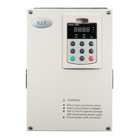
V&T E5-H Series User manual

E5−H High Performance Universal Inverter
User Manual
E5−H Series
USER’S MANUAL
V&T

E5−H High Performance Universal Inverter User Manual
Safety Precautions
Safety Precautions
Description of safety marks:
Danger: The misuse may cause fire, severe injury, even death.
Note: The misuse may cause medium or minor injury and equipment damage.
Use
DangerDanger
zThis series of inverter is used to control the variable speed operation of threephase
motor and cannot be used for singlephase motor or other applications. Otherwise,
inverter failure or fire may happen.
zThis series of inverter cannot be simply used in the applications directly related to the
human safety, such as the medical equipment.
zThis series of inverter is produced under strict quality management system. If the
inverter failure may cause severe accident or loss, safety measures, such as
redundancy or bypass, shall be taken.
Goods Arrival Inspection
NoteNote
zIf the inverter is found damaged or have missing parts, the inverter cannot be installed.
Otherwise, accident may be caused.
Installation
NoteNote
zWhen handling and installing the inverter, please hold the inverter bottom. Do not hold
the enclosure only. Otherwise, your feet may be injured and the inverter may be
damaged because of dropping.
zThe inverter shall be mounted on the fire retardant surface, such as metal, and kept far
away from the inflammables and heat source.
zKeep the drilling scraps from falling into the inverter during the installation; otherwise,
inverter failure may be caused.
zWhen the inverter is installed inside the cabinet, the electricity control cabinet shall be
equipped with fan and ventilation port. And ducts for heat dissipation shall be
constructed in the cabinet.

E5−H High Performance Universal Inverter User Manual
Safety Precautions
Wiring
DangerDanger
zThe wiring must be conducted by qualified electricians. Otherwise, electric shock may
happen or inverter damage.
zBefore wiring, confirm that the power supply is disconnected. Otherwise, electric shock
may happen or fire.
zThe PE terminal must be reliably grounded, otherwise, the inverter enclosure may
become live.
zPlease do not touch the main circuit terminals. The wires of the main circuit terminals
must not contact the inverter enclosure. Otherwise, electric shock may happen.
zThe connecting terminals for the braking resistor are 2/B1 and B2. Please do not⊕
connect terminals other than these two. Otherwise, fire may be caused.
zThe leakage current of the inverter system is more than 3.5mA, and the specific value of
the leakage current is determined by the operation conditions. The inverter and the
motor must be grounded to ensure the safety.
Wiring
NoteNote
zThe threephase power supply cannot connect to output terminals U/T1, V/T2 and
W/T3, otherwise, the inverter will be damaged.
zIt is forbidden to connect the inverter output terminals to the capacitor or LC/RC noise
filter with phase lead, otherwise, the internal components of the inverter may be
damaged.
zPlease confirm that the power supply phases, rated voltage are consistent with those
indicated by the nameplate, otherwise, the inverter may be damaged.
zDo not perform dielectric strength test on the inverter, otherwise, the inverter may be
damaged.
zThe wires of the main circuit terminals and the wires of the control circuit terminals shall
be laid separately or in a squarecrossing mode, otherwise, the control signal may be
interfered.
zThe wires of the main circuit terminals shall adopt lugs with insulating sleeves.
zThe sectional area of inverter input and output cables should be selected according to
the inverter power.
zWhen the cables between the inverter and the motor is longer than 100m, it is
suggested to use output reactor to avoid the inverter failure caused by the overcurrent of
the distribution capacitor.
zThe inverter equipped with a DC reactor must be connected with a DC reactor between
the terminals of ○
+1 and ○
+2, otherwise the inverter will not display after power on.

E5−H High Performance Universal Inverter User Manual
Safety Precautions
Operation
DangerDanger
zPower supply can only be connected after the wiring is completed and the cover is
installed. It is forbidden to remove the cover in live condition; otherwise, electric shock
may happen.
zWhen auto failure reset function or restart function is enabled, isolation measures shall
be taken for the mechanical equipment, otherwise, personal injury may be caused.
zWhen the inverter is powered on, its terminals are still live even when it is in stop state.
Do not touch the inverter terminals; otherwise electric shock may happen.
zThe failure and alarm signal can only be reset after the running command has been cut
off. Otherwise, personal injury may be caused.
NoteNote
zDo not start or shut down the inverter by switching on or off the power supply, otherwise,
the inverter may be damaged.
zBefore operation, please confirm if the motor and inverter are in the normal use range,
otherwise, the inverter may be damaged.
zThe heatsink and the braking resistor have high temperature. Please do not touch such
device; otherwise, you may be burnt.
zWhen the inverter is used by crane or lifting equipment, mechanical contracting brake
shall also be equipped.
zPlease do not change the inverter parameter randomly. Most of the factory settings of
the inverter can meet the operating requirement, and the user only needs to set some
necessary parameters. Any random change of the parameter may cause the damage of
the mechanical equipment.
zIn the applications with power frequency and variable frequency switching, the two
contactors for controlling the industrial frequency and variable frequency switching shall
be interlocked.
Maintenance, Inspection
DangerDanger
zIn the poweron state, please do not touch the inverter terminals; otherwise, electric
shock may happen.
zIf cover is to be removed, the power supply must be disconnected first.
zWait for at least 10 minutes after power off or confirm that the CHARGE LED is off
before maintenance and inspection to prevent the human injury caused by the residual
voltage of the electrolytic capacitor in main circuit.
zThe components shall be maintained, inspected or replaced by qualified electricians.

E5−H High Performance Universal Inverter User Manual
Safety Precautions
NoteNote
zThe circuit boards have large scale CMOS IC. Please do not touch the board to avoid
the circuit board damage caused by ESD.
Others
DangerDanger
zIt is forbidden to modify the inverter unauthorizedly; otherwise, human injury may be
caused.

Contents
Chapter 1 Introduction to E5−H Series Inverter....................................................................................1
1.1 Product Model Description.....................................................................................................................1
1.2 Product Nameplate Description .............................................................................................................1
1.3 Product Series .......................................................................................................................................2
1.4 Technical Specifications of Product........................................................................................................3
1.5 Product Component Name ....................................................................................................................5
1.6 Product Outline, Mounting Dimension, and Weight................................................................................5
1.7 Operation Panel Outline and Mounting Dimension ................................................................................7
1.8 Pallet Outline and Mounting Dimension .................................................................................................7
1.9 Braking Resistor Lectotype ....................................................................................................................8
Chapter 2 Inverter Installation................................................................................................................9
2.1 Environment for Product Installation ......................................................................................................9
2.2 Mounting Direction and Space ...............................................................................................................9
2.3 Removal and Mounting of Operation Panel and Cover........................................................................10
Chapter 3 Wiring of Inverter .................................................................................................................14
3.1 Connection of the Product and Peripheral Devices .............................................................................14
3.2 Description of Peripheral Devices for Main Circuit ...............................................................................15
3.3 Lectotype of Main Circuit Peripheral Devices ......................................................................................15
3.4 Product Terminal Configuration............................................................................................................16
3.5 Functions of Main Circuit Terminal .......................................................................................................16
3.6 Attention for Main Circuit Wiring...........................................................................................................17
3.7 Terminal Wiring ....................................................................................................................................20
3.8 Functions of Control Circuit Terminals .................................................................................................21
3.9 Schematic Diagram of Control Board...................................................................................................24
3.10 Lectotype of Control Circuit Peripheral Devices.................................................................................24
3.11 Description of Jumper Function..........................................................................................................24
Chapter 4 Using Instructions of Operation Panel ..............................................................................25
4.1 Introduction to Operation Panel ...........................................................................................................25
4.2 Descriptions of Indicators.....................................................................................................................25
4.3 Description of Keys on Operation Panel ..............................................................................................26
4.4 Menu Style ...........................................................................................................................................27
4.5 Password Operation ............................................................................................................................32
4.6 Lock/Unlock Keys ................................................................................................................................33
4.7 Operation Panel Display and Key Operation .......................................................................................34
4.8 Operation Example ..............................................................................................................................35
4.9 Running for the First Time....................................................................................................................37
Chapter 5 List of Parameters ...............................................................................................................38
5.1 List of Basic Menu Function Codes......................................................................................................38

5.3 User’s Connection Diagram .................................................................................................................51
Chapter 6 Parameters Description ......................................................................................................53
6.1 Basic Function Parameter (Group P0) .................................................................................................53
6.2 Main and Auxiliary Reference Parameter (Group P1) ..........................................................................57
6.3 Key and Display Parameters (Group P2).............................................................................................61
6.4 Startup/stop Parameter (Group P3) .....................................................................................................63
6.5 Multisection Parameter (Group P4) ...................................................................................................65
6.6 Multifunctional Input Parameter (Group P5).......................................................................................68
6.7 Analog Reference Parameter (Group P6) ............................................................................................75
6.8 Multifunction Output Parameter (Group P7).......................................................................................78
6.9 Process PID Close Loop Parameters (Group P8)................................................................................85
6.10 Motor Parameter (Group P9) .............................................................................................................87
6.11 Control Parameter (Group PA) ...........................................................................................................90
6.12 Enhanced Function Parameter (Group Pb)........................................................................................95
6.13 Communication Parameters (Group PC) .........................................................................................101
6.14 Reserved .........................................................................................................................................101
6.15 Failure Record Parameters (Group d0)............................................................................................101
6.16 Product Identity Parameters (Group d1) ..........................................................................................102
6.17 Use of Display Parameters (Group d2)............................................................................................102
6.18 Special Parameters for Constant Pressure Control (Group H0) ........................................................103
Chapter 7 Fault Diagnosis ..................................................................................................................107
7.1 List of Fault and Alarm Information ....................................................................................................107
7.2 Troubleshooting Procedures .............................................................................................................. 111
Chapter 8 Routine Repair and Maintenance........................................................................................112
8.1 Routine Maintenance.........................................................................................................................112
8.2 Periodic Maintenance ........................................................................................................................113
8.3 Component Replacement ..................................................................................................................113
8.4 Insulation Test ....................................................................................................................................114
Appendix A Modbus Communication Protocol ................................................................................115
Appendix B Control Mode Setting Process ......................................................................................124
1. Setting Process for Autotuning...........................................................................................................124
2. Setting Process for Open Loop............................................................................................................125
3. Setting Process for Closed Loop .........................................................................................................127
Appendix C FAQ..................................................................................................................................129

E5−H High Performance Universal Inverter User Manual
Chapter 1 Introduction to E5−H Series Inverter 1
Chapter 1 Introduction to E5−H Series Inverter
1.1 Product Model Description
The digits and letters in the inverter model field on the nameplate indicate such information as the
inverter series, power supply class, power class and software versions.
E5 -H4T
11G
V/F control technology
platform with vector control
4:400V
T:Three-prase
11G:11kW Constant
torque/heavy-duty
-
H Universal series
1.2 Product Nameplate Description

E5−H High Performance Universal Inverter User Manual
2 Chapter 1 Introduction to E5−H Series Inverter
1.3 Product Series
E5H4TG Threephase 400V Constant torque/heavyduty application
Power (kW) 0.75 1.5 2.2 3.7 5.5 7.5 11 15 18.5 22 30 37 45 55 75
Motor
power (kW) 0.75 1.5 2.2 3.7 5.5 7.5 11 15 18.5 22 30 37 45 55 75
Voltage (V) Threephase 0 to rated input voltage
Rated current (A) 2.5 3.8 5.5 9 13 17 24 30 39 45 60 75 91 112 150
Output
Overload
capacity
150% 1 minute, 180% 10 seconds, 200% 0.5 second, interval: 10 minutes (inverse time lag
feature)
Rated
voltage/frequency Threephase 380V/480V; 50Hz/60Hz
Allowable voltage
range 323V ~ 528V; Voltage imbalance 3%; allowable frequency fluctuation: ±5%
Input
Rated current (A) 2.8 4.2 6.1 10 15 19 26 33 43 50 66 83 100 123 165
Braking unit* Builtin as standard Builtin as option
Protection class IP20
Cooling mode Naturalcooling Forced air convection cooling
Power (kW) 90 110 132 160 185 200 220 250 280 315 355 4 00 4 50 500
Motor
power (kW) 90 110 132 160 185 200 220 250 280 315 355 400 450 500
Voltage (V) Threephase 0 to rated input voltage
Rated current (A) 176 210 253 304 350 380 426 470 520 600 650 690 775 860
Output
Overload
capacity
150% 1 minute, 180% 10 seconds, 200% 0.5 second, interval: 10 minutes (inverse time lag
feature)
Rated
voltage/frequency Threephase 380V/480V; 50Hz/60Hz
Allowable voltage
range 323V ~ 528V; Voltage imbalance 3%; allowable frequency fluctuation: ±5%
Input
Rated current (A) 160* 196* 232* 282* 326* 352* 385* 437* 491* 580* 624* 670* 755* 840*
Braking unit External braking unit needed
Protection class IP20
Cooling mode Forced air convection cooling
*E5H4T90G and above products are equipped with external DC reactor as standard.
*For E5H series product, below 15kw brake unit built-in as standard, above 15KW inverter, we can provide
brake unit for out-connected with inverter

E5−H High Performance Universal Inverter User Manual
Chapter 1 Introduction to E5−H Series Inverter 3
1.4 Technical Specifications of Product
Control mode Process open loop control
Startup torque 0.50Hz 180%
Speed adjustment range 1:100
Control
features
Speed stabilization
precision ± 0.5%
Key functions
Undervoltage adjustment, switching of AC operation grounding, protective
grounding and DC operation grounding, rotation speed tracing, torque
limitation, multispeed operation (up to 16 speeds), auto−tuning, S curve
acceleration/deceleration, slip compensation, PID regulation, current limiting
control, manual/auto torque increase, current limiting.
Frequency setting mode
Frequency can be set via operation panel, UP/DN terminal, or analog inputs
of AI1 and AI2, and can also be set through communication with host
computer,
Frequency range 0.00 ~ 300.00Hz
Startup frequency 0.00~60.00Hz
Acceleration/deceleration
time 0.1~36000s
Powered braking
capacity Braking unit action voltage: 650 ~ 750V
DC braking capacity
DC braking initial frequency: 0.00 ~ 300.0Hz; DC braking current: Constant
torque: 0.0 ~ 120.0%, Variable torque: 0. 0 ~ 90.0%
DC braking time: 0.0 ~ 30.0s; there is no initial waiting time for the DC braking
to realize quick braking
Product
functions
Magnetic flux braking
function
Ongoing action and no action upon deceleration as option, no action upon
deceleration at default
Multifunctional M key
The unique multifunctional key is used to set the frequently used operations:
JOG, emergent stop, Running command issuing mode switch , menu
switching
Multiple menu modes Basic menu mode, fast menu mode. Menu mode of nonfactory setting
function codes, Menu mode of last changed 10 function codes
Parameter copy
The standard operation panel can realize the parameter upload, download
and display the copy progress. User can select to forbid the overwriting of the
uploaded parameters.
Displayed/hidden
function code The customer can select to display or hide the function codes byhimself.
Dual RS485
communication ports
Support Modbus protocol (RTU). The standard operation panel can realize
the function of remote control box with a maximum distance of 500m.
Operation panel Button type or shuttle type operation panel optional, protection class: IP20 as
standard, IP54 as option
Shared DC bus The full series can realize shared DC bus supply for several inverters.
Independent duct The full series adopts independent duct design and supports the installation
of heatsink outside the cabinet
Unique
functions
Powerup
auto−detection
Realizing the powerup autodetection of internal and peripheral circuits,
including motor grounding, abnormal +10V power supply output, abnormal
analog input, and disconnection

E5−H High Performance Universal Inverter User Manual
4 Chapter 1 Introduction to E5−H Series Inverter
Protection
function
Power supply undervoltage, overcurrent protection, overvoltage protection, interference protection,
abnormal comparison reference input, auto−tuning failure, module protection, heatsink overtemperature
protection, inverter overload protection, motor overload protection, peripheral protection, abnormal current
detection, output to ground short circuit, abnormal power failure during operation, abnormal input power,
output phase failure, abnormal EEPROM, relay suction pull-on anomaly, temperature sensor taking
sample anomaly, abnormal +10V power supply output, abnormal analog input, motor overtemperature
(PTC), abnormal communication, abnormal version compatibility, abnormal copying, terminal mutual
exclusion detection failure, hardware overload protection
Efficiency At rated power, 7.5kW and below power class 93%, 45kW and below power class 95%, 55kW and
above power class 98%
Operating site
The inverter shall be mounted vertically in the electric control cabinet with
good ventilation. Horizontal or other installation modes are not allowed. The
cooling medium is the air. The inverter shall be installed in the environment
free from direct sunlight, dust, corrosive gas, combustible gas, oil mist, steam
and drip.
Ambient temperature 10 ~ +40ºC, derated at 40 ~ 50ºC, the rated output current shall be
decreased by 1% for every temperature rise of 1ºC
Humidity 5 ~ 95%, no condensing
Altitude 0 ~ 2000m, derated above 1000m, the rated output current shall be
decreased by 1% for every rise of 100m
Vibration 3.5mm,2~9Hz; 10 m/s2,9~200Hz; 15 m/s2,200~500Hz
Environment
Storage temperature 40~+70ºC

E5−H High Performance Universal Inverter User Manual
Chapter 1 Introduction to E5−H Series Inverter 5
1.5 Product Component Name
E5H4T7.5G and below power class E5H4T11G and above power class
Figure 11 Product component name
1.6 Product Outline, Mounting Dimension, and Weight
Figure 12 Product outline and mounting dimension
E5H4T7.5G and below
p
ower class
E5H4T11G and above power class
Cover
Mounting hole
Cooling fan
Nameplate
Operation panel
Cover
Mounting hole
Cooling fan
Enclosure
Nameplate
Dust guard
Nameplate
Leading board
Dust guard
Upper cove
r
Operation panel
Lower cove
r
Heatsink
Mounting hole

E5−H High Performance Universal Inverter User Manual
6 Chapter 1 Introduction to E5−H Series Inverter
Product outline, mounting dimension, and weight
Outline and mounting dimension (mm)
Voltage
class
Inverter model
W H D W1 H1 D1 T1
Mounting
hole
diameter
Approximate
weight
(kg)
E5H4T0.75G 118 190 155 105 173 40.8 3 5.5 1.5
E5H4T1.5G
E5H4T2.2G
E5H4T3.7G
118 190 175 105 173 60.5 4 5.5 2.6
E5H4T5.5G
E5H4T7.5G
155 249 185 136 232 69 8 5.5 4.5
E5H4T11G
E5H4T15G
210 337 200 150 324 88 2 7 8.5
E5H4T18.5G
E5H4T22G
E5H4T30G
289 440 220 200 425 88 2.5 7 17
E5H4T37G
E5H4T45G
319 575 218 220 553 90.5 2.5 10 25
E5H4T55G
E5H4T75G
404 615 255 270 590 86.5 3.0 10 35
E5H4T90G
E5H4T110G
465 745 325 343 715 151.5 3.0 12 55
E5H4T132G
E5H4T160G
E5H4T185G
E5H4T200G
540 890 385 370 855 205.5 4.0 14 85
E5H4T220G
E5H4T250G
E5H4T280G
700 1010 385 520 977 210 4.0 14 125
E5H4T315G
E5H4T355G
810 1358 425 520 1300 210 4.0 14 215
E5H4T400G
E5H4T450G
400V
E5H4T500G
810 1358 425 520 1300 210 4.0 14 215

E5−H High Performance Universal Inverter User Manual
Chapter 1 Introduction to E5−H Series Inverter 7
1.7 Operation Panel Outline and Mounting Dimension
Shuttle type operation panel
(V6DP01)
Button type operation panel
(V6DP02)
Rear view of operation panel
Figure 13 Operation panel outline and mounting dimension
Note:
E5H4T7.5G and below power class are equipped with shuttle type operation panel (V6DP01) as
standard, E5H4T11G and above power class are equipped with button type operation panel
(V6DP02) as standard.
1.8 Pallet Outline and Mounting Dimension
V6DP05 is the mounting pallet when the operation panel is to install on the electric control cabinet. The
outline and dimension are as follows:
Pallet (V6DP05) Openporedimensionofpallet
Figure 14 Pallet outline and mounting dimension

E5−H High Performance Universal Inverter User Manual
8 Chapter 1 Introduction to E5−H Series Inverter
1.9 Models of Braking Resistor
Braking resistor unit
Inverter model Braking unit
Power Resistor Minimum
limit resistor Qty.
Braking
torque%
E5H4T0.75G 110W 7501251 130
E5H4T1.5G 260W 4001001 125
E5H4T2.2G 320W 2501001 135
E5H4T3.7G 550W 15066.71 135
E5H4T5.5G 800W 10066.71 135
E5H4T7.5G 1070W 7566.71 130
E5H4T11G 1600W 50251 135
E5H4T15G
Builtin as
standard
2000W 40251 125

E5−H High Performance Universal Inverter User Manual
Chapter 2 Inverter Installation 9
Chapter 2 Inverter Installation
2.1 Environment for Product Installation
Do not install the inverter in the sites with oil mist, metal powder and dust.
Do not install the inverter in the sites with hazardous gas and liquid, and corrosive, combustible and
explosive gas.
Do not install the inverters in salty sites.
Do not install the inverter in the sites with direct sunlight.
Do not mount the inverter on the combustible materials, such as wood.
Keep the drilling scraps from falling into the inverter during the installation.
Mount the inverter vertically in the electric control cabinet, mount the cooling fan or air conditioner
to prevent the ambient temperature from rising to above 45 ºC.
For the sites with adverse environment, it is recommended to mount the inverter heatsink outside
the cabinet.
2.2 Mounting Direction and Space
In order not to reduce the inverter cooling effect, the inverter must be mounted vertically, and certain
clearance must be maintained, as shown in Figure 21 and Figure 22.
Figure 21 Mounting direction and clearance E5H4T7.5G and below power class
Air circulation position
Above 120mm
Above 120mm
Air circulation position
Above 120mm
Above 120mm
Above 30mm Above 30mm

E5−H High Performance Universal Inverter User Manual
10 Chapter 2 Inverter Installation
"Note:
When the E5H4T7.5G and below power class inverters are mounted side by side in the cabinet,
please remove the upper dust filter and the lower leading board.
Figure 22 Mounting direction and space for E5H4T11G and above power class
2.3 Removal and Mounting of Operation Panel and Cover
2.3.1 Removal and Mounting of Operation Panel
Removal of operation panel
As shown in Figure 23, the grab the operation panel forcefully in direction 1, and then lift the panel
body in direction 2.
Mounting of operation panel
As shown in Figure 24, align with the lower clamping position of the operation panel in direction 1,
and then press down the operation panel in direction 2, until the “crack” sound is heard.
Do not mount the operation panel in any other direction; otherwise, the operation panel will have
poor contact.
Above 100mm Above 100mm
A
ir circulation
position
A
ir circulation
position Above 200mm
Above 200mm
Air circulation position Above 200mm
Air circulation position
Above 200mm

E5−H High Performance Universal Inverter User Manual
Chapter 2 Inverter Installation 11
Figure 23 Removal of operation panel Figure 24 Mounting of operation panel
2.3.2 Removal and Mounting of Covers of Inverter with Plastic Enclosure
Removal of operation panel
Please refer to 2.3.1 removal and mounting of operation panel.
Removal of lower cover
After removing the mounting screws of the cover, press the left and right sides of the cover
forcefully in direction 1 and at the same time lift the cover in direction 2, as shown in Figure 25.
Removal of upper cover
As shown in Figure 26, press the left and right sides of the cover forcefully in direction 1, and at
the same time lift the cover in direction 2.
Figure 25 Removal of lower cover Figure 26 Removal of upper cover
Mounting of upper cover
After connecting the cables of main circuit terminals and control circuit terminals, insert the upper
claw grab of the upper cover into the groove of the inverter body, as shown in position 1 in Figure

E5−H High Performance Universal Inverter User Manual
12 Chapter 2 Inverter Installation
27, and then press the lower part of the upper cover in direction 2 as shown in Figure 27, until the
“crack” sound is heard.
Mounting of lower cover
Insert the upper claw grab the lower cover into the groove of the upper cover, as shown in position
1 of Figure 28, and then press the lower part of the lower cover in direction 2 of Figure 28, until
the “crack” sound is heard. Now, tighten the cover screws.
Figure 27 Mounting of upper cover Figure 28 Mounting of lower cover
Mounting of operation panel
Please refer to 2.3.1 Removal and mounting of operation panel.
2.3.3 Removal and Mounting of Covers of E5H4T11G~E5H4T75G and Above Power
Class Inverter with Sheetmetal Enclosure
Removal of operation panel
Please refer to 2.3.1 Removal and mounting of operation panel.
Removal of cover
Remove the mounting screws on the lower part of the cover, lift the cover in direction 1 as shown in
Figure 29, and then take out the cover in direction 2.
Mounting of cover
After connecting the cables of main circuit terminals and control circuit terminals, cramp the cover in
direction 1 as shown in Figure 210, press down the cover in direction 2 and then tighten the cover
screws.

E5−H High Performance Universal Inverter User Manual
Chapter 2 Inverter Installation 13
Figure 29Removalofcover Figure210 Mounting of cover
Mounting of operation panel
Please refer to 2.3.1 Removal and mounting of operation panel.
"Note:
Do not directly mount the cover with operation panel on the inverter, otherwise, the operation panel will
have poor contact.
2.3.4 Open and Close of Doors of E5H4T90G and Above Power Class Inverter with
Sheetmetal Enclosure
Opening of the door
Press the latch following direction 1 in Figure 211 and open the door following direction 2.
Removal of operation panel
The operation panel is connected to the control board through the standard network cable and will not
interfere with the open/close of the door. To remove the operation panel, refer to section 2.3.1 Removal
and Mounting of Operation Panel
Mounting of cover
After connecting the cables of main circuit terminals and control circuit terminals, close the door
following direction 1 in Figure 212, and then press down the latch following direction 2 to lock the door.
Figure 211Openingthedoor Figure212 Closing the door
Table of contents
Other V&T Inverter manuals