Vanguard HD Mega pixel User manual

Vanguard-HD Mega pixel
IR OUTDOOR CAMERA
INSTRUCTION MANUAL


CONTENTS
1
WARNING & CAUTION 2
GENERAL FEATURES 4
NAME OF EACH PART 5
INSTALLATION 7
CONNECTION 11
SPECIFICATIONS 12
OSD MENU SETTING 14
TROUBLESHOOTING 16
DIMENSIONS 17

If you fail to read this information and handle the product incorrectly, death or
serious injury may occur.
The unit should be installed by the trained Personnel.
Switch off immediately if the product emits smoke or abnormal heat.
Never install the product in area exposed to oil or gas.
Never touch the power cord with wet hands.
Clean only with dry cloth.
Ensure that the product is not subjected to strong impacts and vibration.
Never expose the camera to direct sunlight
Never disassemble the unit by
unauthorized person.
Serious and Permanent
damage will occur.
WARNING
WARNING & CAUTION
2

CAUTION: TO REDUCE THE RISK OF ELECTRIC SHOCK,
DO NOT REMOVE COVER (OR BACK).
NO USER SERVICEABLE PARTS INSIDE.
REFER SERVICING TO QUALIFIED SERVICE PERSONNEL.
This symbol is intended to alert the user to the presence of
un-insulated "dangerous voltage" within the product's enclosure
that may be of sufficient magnitude to constitute a risk of electric
shock to persons.
This symbol is intended to alert the user to the presence of
important operating and maintenance (servicing) instructions in
the literature accompanying the appliance.
CAUTION
RISK OF ELECTRIC SHOCK
DO NOT OPEN
WARNING & CAUTION
LABEL
4. SCREW M4x20 4EA
5. CALBLOCK 6x30 4EA
6. SCREW 4x30 4EA
7. CAP SCREW 2EA
3

*
*
*
*
*
*
*
*
*
*
*
*
*
*
*
1/3" Panasonic 2.2M Progressive Scan CMOS
Privacy Masking, Motion Detection, Sharpness control and shading
HD-SDI : 1080@30p/25p, 720@60p/50p
NTSC, PAL CVBS without WDR
TDN ICR Mega pixel lens
40PCS High performance IR LEDs
Joystick type OSD control key
Wide Dynamic Range compensation
Adaptive Contrast Enhancer
Supports various digital features of Mirror, Flip, Digital Zoom,
IP-67 rated waterproof frame housing
3-Axis bracket (Wall, Ceiling, Pole mount available)
Easy installation by hinge type junction box (option)
Adjustable Zoom & Focus of the lens externally
Adjustable Day & Night lux level value
Fan & Heater (option)
GENERAL FEATURES
4

NAME OF EACH PART
FIG.1
1. Sunvisor
2. Camera Body
3. Function Cover
4. Function Part
5. IR LED Lamp
6. Lens
7. Camera Bracket
8. Lens Control Lever
9. Set Screw groove for Sunvisor
10. X-Axis Set Screw
11. Y-Axis Set Screw
12. Z-Axis Set Screw
5
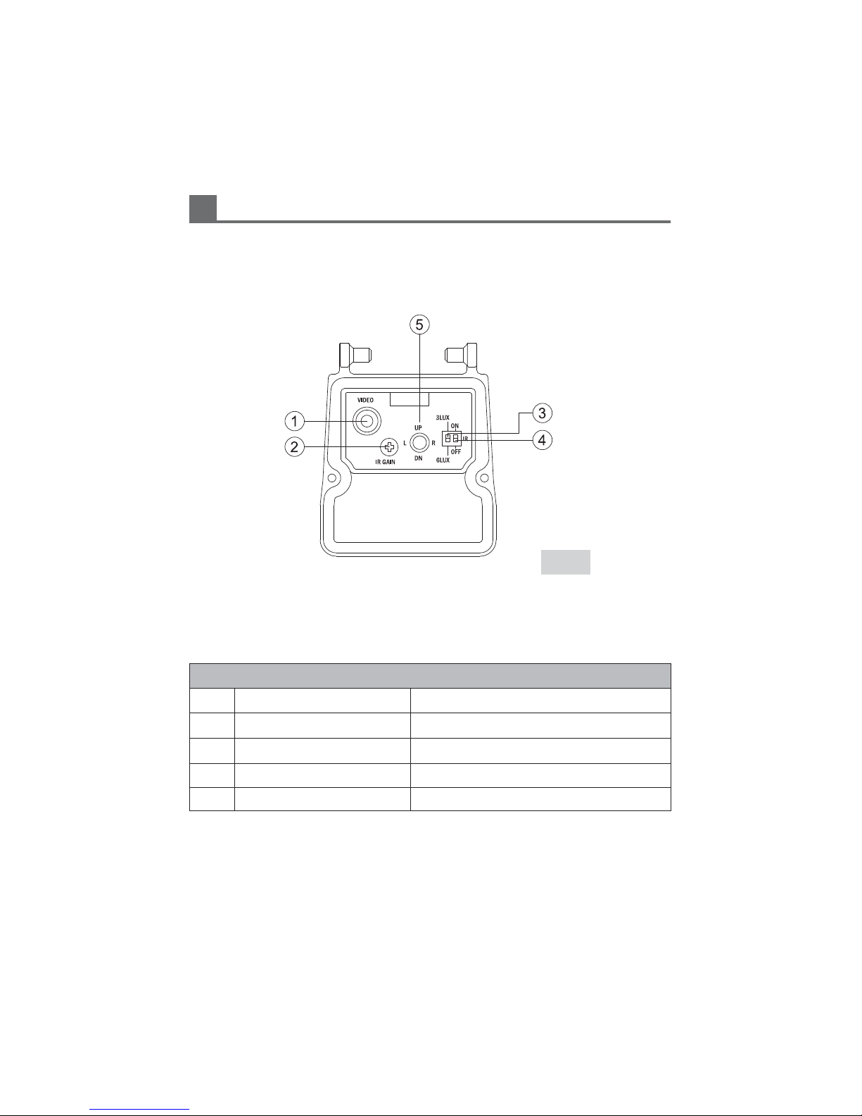
NAME OF EACH PART
FUNCTION PART
FUNCTION
1Extra Video Out CVBS Output
2IR Gain IR Gain Control
33 Lux / 6 Lux CDS Sensitivity Control
ON / OFF IR LED ON / OFF
4
OSD Button Up, Down, Set, Left, Right
5
FIG.2
6

INSTALLATION
FIG.3 FIG.4
FIG.5
1. When you need to install a camera on the surface of a concrete wall, you can drill
a hole like Fig.3 exactly by using a Template Card offered by accessory.
2. As Fig.4, please set a Calblock in the hole of the wall.
3. After connect a Power Jack and Video Connector. Please wrap and tighten by
using a seal tape (water-proof tape) to prevent a leak of water.
Template Label
81mm
86mm
Seal Tape
6mm
Calblock( 6x30)
Hole Diameter : 6mm
Depth : 30mm
7

INSTALLATION
FIG.6
4. Like Fig.6, after put the cable connector part into the bracket, please fix the
bracket on the wall by use of screws.
5. Like Fig.7, after set the camera to desired direction, please fix tightly by L-Wrench.
6. After finish adjustment of OSD function, please tighten the screw tightly to prevent
a leak of water close the cover then. (Fig.8)
FIG.7
FIG.8
Wrench 2mm
Wrench 3mm
Screw 4x30
8
This manual suits for next models
1
Table of contents


