©Vantage, 8/23/2016 / IS-0664-A RadioLink® RS-232 Station — MODEL: STC2RR001 page 1 of 2
INSTALLATION
VANTAGECONTROLS.COM VANTAGE INSTALL GUIDES
2168 West Grove Parkway, Suite 300, Pleasant Grove, UT. 84062 USA
Telephone: 801 229-2800 ●Fax: 801 224-0355 RadioLink® RS-232 Station — MODEL: STC2RR001
Overview
The STC2RR001 connects to RS-232 devices and
communicates to Vantage via RadioLink communication. This
design eliminates wire runs normally needed for interfacing
with RS-232 devices. The Vantage System may be
programmed to control RS-232 devices, or vice versa. Among
the ever-growing list of devices that communicate via RS-232
are Audio/Video, Drape Controls, Pool Systems, Security
Systems, Touch screens, PCs, etc. The system also allows
“recognition” of RS 232 strings from third party devices. When
these strings are sent to or monitored by the Vantage System
any custom program may be executed.
System Specifications/Requirements
Description Specification
Dimensions, HWD
3.8” x 2.4” x 0.88” (minus antenna)
-or-
97mm x 61mm x 22mm (minus antenna)
Weight 8.2oz -or- 119g
RS-232 Male to Male NULL Adaptor Included
RX, TX, GND PINS
LED Indicators
Data Out (TX)
Data In (RX)
Handshake Out (RTS)
Handshake In (CTS)
Diagnostic (Configured Status)
Power Supply Requires 9-12VDC, 200mA
(adaptor recommended VFA-0008)
Station Bus Wiring NONE
Station Equivalent Counts as 1 RF Station on RadioLink
Enabler
Ambient
Operating
Temperature
32-95°F -or- 0-35°C
Ambient
Operating
Humidity
5-95% non-condensing
Finish Black
Software/Firmware
InFusion Systems or QLink Software 3.3 or higher and
Firmware 6.3 or higher are required. For new projects it is
recommended that firmware and software be kept to the most
current release.
Mounting
Installation of Vantage products should be performed or
supervised by a Certified Vantage Installer. The RS-232 Station
is connected to the equipment it will be interfacing with. The
small package will fit into most enclosures, or hang behind the
equipment. Velcro tape may be helpful in some installations.
Station Connection
The STC2RR001, RF RS-232 Station connects to a Vantage
System via a RadioLink Enabler. The serial number must be
typed into the software project file and the Vantage System
programmed before the connection is complete.
Use Vantage’s VFA-0008 power adapter, INPUT: 120-240Vac
60/50Hz, OUTPUT: 12VDC 1.5A. Connect the power source to
the IN, plus and minus terminals. If more than one STC2RR001
station is used with the same power supply, the power supply
must be rated at 200mA minimum, for each station added. The
second station may be connected using the OUT, plus and
minus terminals on the first station to the IN terminals on a
second station. The power supply mentioned above, VFA-
0008, has an output rating of 12VDC, 1.5A and should be able
to handle this. The connection to a third party RS-232 device is
completed with the DB9 connector provided on the
STC2RR001 station. The pin out summary is provided below
along with the wire colors for custom connections.
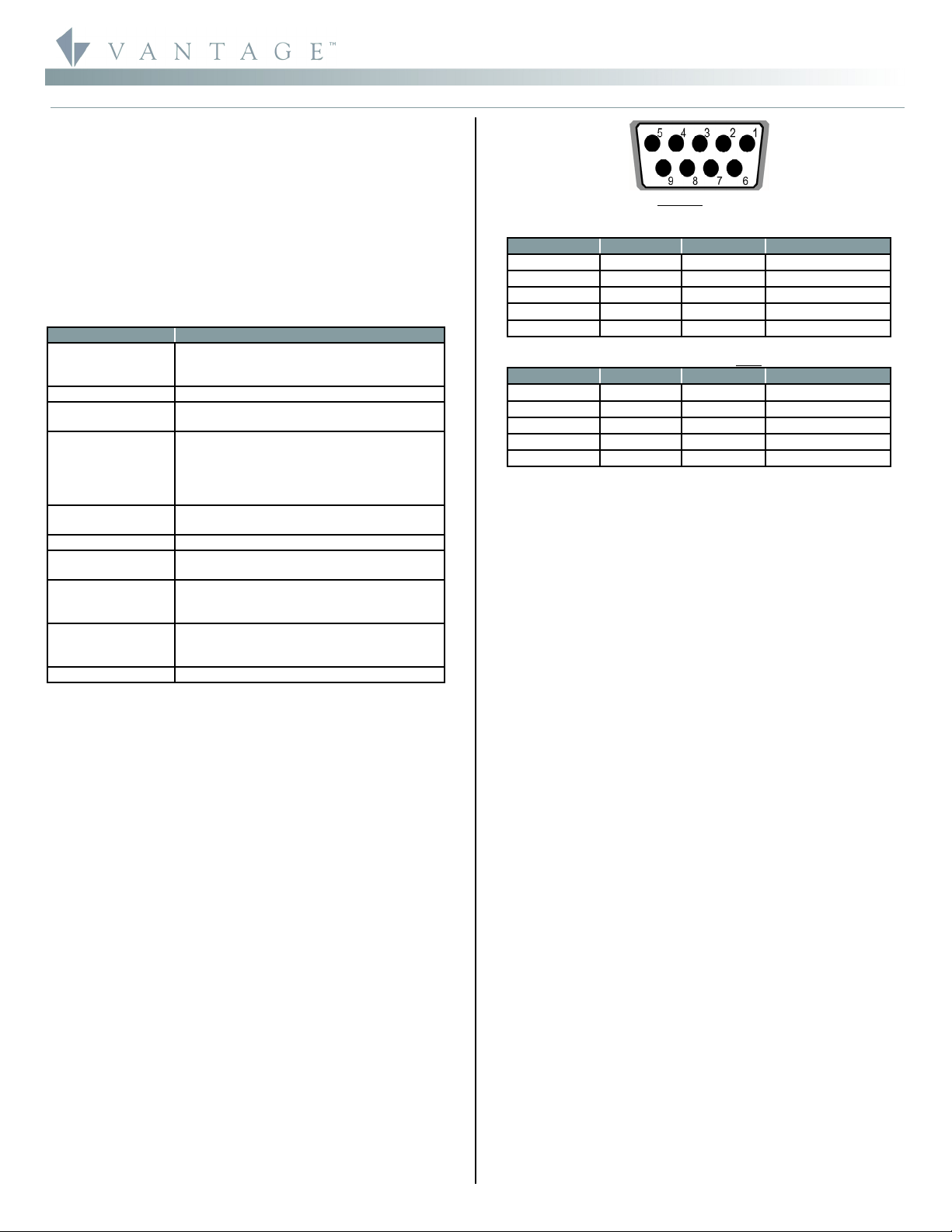
DB9 Female Connector
Q-RS232S Connector Signal Summary
Connect to DB9 Pin Wire Color Description
RX 2 Brown Receive Data
TX 3 Red Transmit Data
GND 5 Yellow Ground
CTS 7 Blue Handshake In
RTS 8 Violet Handshake Out
Q-RS232S Connector With RS-232 Null Adaptor (included)
Connect to DB9 Pin Wire Color Description
RX 2 Brown Transmit Data
TX 3 Red Receive Data
GND 5 Yellow Ground
CTS NA
RTS NA
STC2RR001 Setup With Design Center
First select the room, then click on Vantage Objects in the
Object Explorer and expand Stations, RadioLink. From the list
of stations double click on the RS-232 Station to place it in the
room. In the Object Editor name the station and make sure it is
on the correct RadioLink bus port. Make sure the
communication protocol is setup to match the equipment it
will be communicating with. With the RS-232 Station defined,
it may be used to transmit and receive RS-232 Strings. When
you program a task and select the Send Serial String
procedure, the RS-232 station’s port will be an option as a
destination.
STC2RR001 Setup With QLink
In Location view, select the floor and room to add the
STC2RR001 Station in. Right click on the Room and from the
popup menu select Add RadioLink Station and select the RS-
232 station from the list. The RadioLink RS-232 Station
Properties dialog box appears. Select the options for baud rate,
parity, the number of data and stop bits and the type of
handshaking if any. With the RS-232 Station defined, it may be
used to transmit and receive RS-232 Strings. When
programming a button and selecting the RS-232 function or
when setting up a String Control the RS-232 Station will be an
option as a destination.
STC2RR001 for System “Tweaks” on QLink Systems
Once connected to the RadioLink Bus, the RS-232 Station is
ready to be connected to a PC to make small system
programming changes with QLink. Connect the PC and the
RS232 with a 9-pin male to 9-pin female straight through RS
232 cable. The RS-232 station should not be used to program
the Vantage System, instead do a Connect Only and make
minor changes to the program while online. For most
programming it is recommended that the QLink connection be
directly to the Main Controller. Do not use the STC2RR001,
RS232 station to configure stations.
Configuration
When the STC2RR001 is first powered, the diagnostic LED will
blink three times followed by a pause. This means the RS-232
Station is not on line with the RadioLink Network and is not
configured. From Design Center, click on the RS-232 Station
and in the Object Editor highlight the Serial Number section
and type the serial number in. Please note, if the serial number
contains an alpha character please ignore this when typing in
serial number. The station will come on line the next time the


