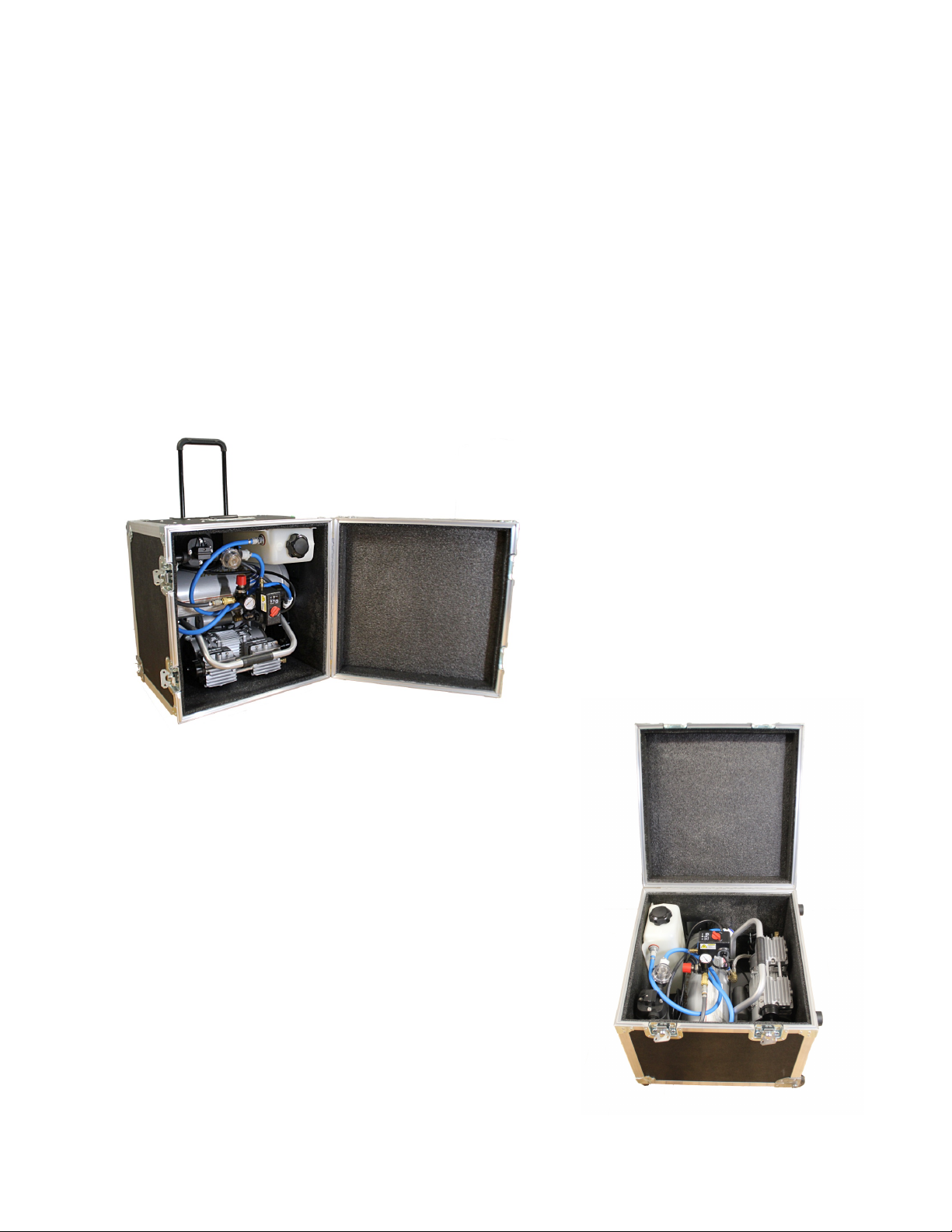
Switch On The Air Compressor. (FIG 4)
1. Turn the power switch from “OFF” to “AUTO”."
2. Use the pressure knob to set the Correct Air Pressure for the
VaporFlame units desired. (SEE VaporFlame Unit manuals for
correct pressure settings.)"
"
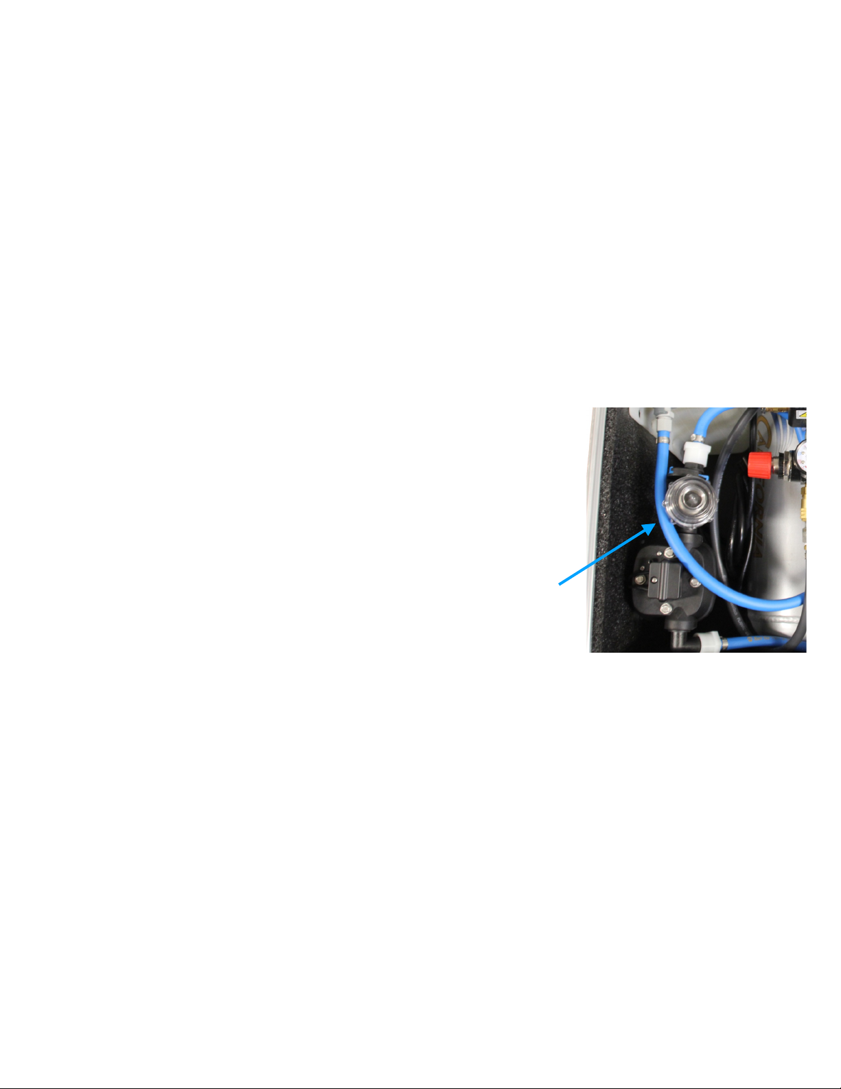
Connect Air/Water Hoses and Prime the System
(FIG 5)
1. Use VaporFlame Air/Water hoses, (sold separately) to
connect The Engine to the VaporFlame effects units."
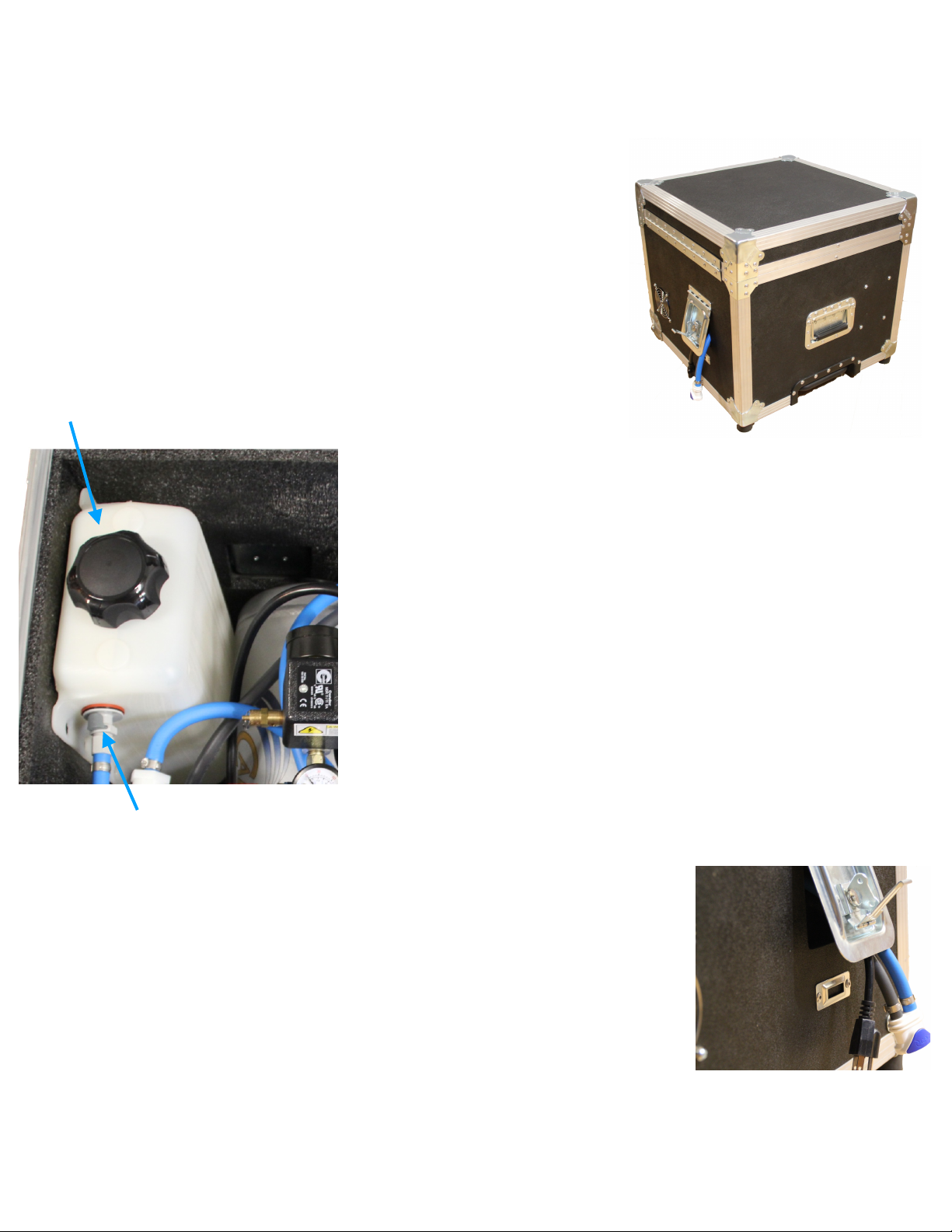
2. Prime the water pump & clear air from the water line.
Using the Water Bleeder Valve, bleed the air from the
water line. This is best done into a container as water
will most likely come out with the air. Once the water
runs as a steady stream without pockets of air,
disconnect the Bleeder Valve."
3. Connect the Air/Water hose to the VaporFlame effect
units. "
Set up your VaporFlame Effect unit
1. Power up the VaporFlame effect and lighting fixture per their manuals. "
"
Drain remaining water from the unit before
storage.
1. Disconnect the VaporFlame effects units from the Air/Water
hoses."
2. Connect the Air/Water Blow OffValve in-line directly after the
The Engine, and before the hoses. "
3. Move the valve lever to the Air (Gray) hose. This sends air
through the water line to clear the water from the hose."
4. Connect the Bleeder Valve at the end of the Air/Water hose line. This allows
the water to be blown out of the water line to prepare it for storage."
5. Once the water has been cleared from the hoses, the hoses may be disconnected
and stored."
6. NOTE: Release the residual air pressure in the air AND water hoses by depressing
the male connectors. A puffof air will result. Neat huh? %